THE AI TAB

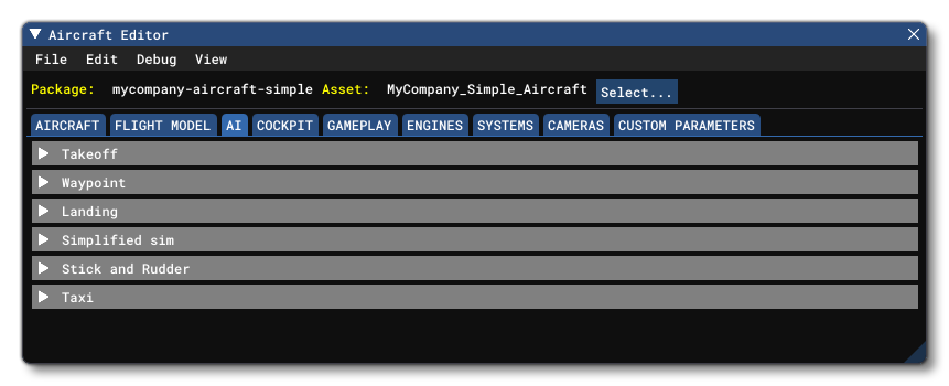
The AI tab is critical when it comes to defining an aircraft as it contains the information required to tweak the co-pilot and Air Traffic AI behavior. Below you can find information on the different sections used to define these AI elements as well as what parameters and values are expected within them.
Takeoff
 This section controls the different takeoff options for the AI. The available parameter is:
- Take Off Flaps Position: This sets the desired flaps position during initial takeoff rollout for AI. This is a value between 0.0 and 1.0, where 0.0 is 0% and 1.0 is 100%.
Waypoint
 This section controls how the AI will deal with taxiway points, specifically the way it will move between them. Available parameters are:
- Slow Down Distance: The distance, in meters, at which the vehicle will start slowing down before reaching a sharp turn or its destination.
- Stop Distance: The distance, in meters, from the destination at which the vehicle considers that it has reached its destination, and will start actually braking to reach a full stop.
- Slow Down On Last WayPoint: When checked, this will tell the vehicle that it should start really slowing down (but not trying to fully stop), on the last 5 meters before reaching its destination.
- Can Reverse: When checked, this parameter tells the AI that the vehicle can reverse.
- Front Radius Meters: The length, in meters, from the center of the vehicle to the front of it. This value is used by the AI to better manage turns. You may set this to -1.0m, in which case the simulation will use an approximate exaggerated value, computed by using a rough bounding box around the model.
Landing
 This section controls how the AI will deal with landing and will be used by both air traffic and the co-pilot. Available parameters are:
- Flare Angle: This setting defines the "ideal" flare angle, in degrees, for the aircraft when coming in to land, just after final approach and before actual touchdown.
- Max Pitch Rate: This sets the maximum rotational speed - in degrees per second - to change the aircraft pitch during landing.
Simplified Sim
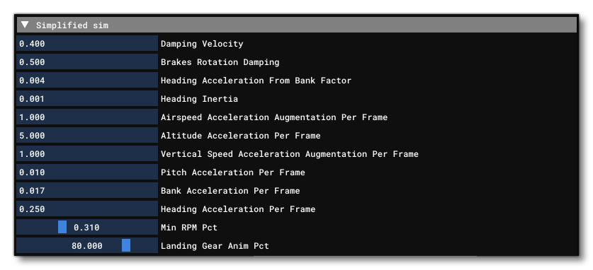
 This section defines some characteristics of simplified versions of the SimObj and flight model parameters that are only for AI aircraft air traffic. AI traffic doesn't care at all about the wind, about remaining fuel, or most of the other world and physical parameters that are important to the user aircraft. The AI aircraft are done this way for performances reasons, but can still visually look correct to the user as long as the following parameters are correctly defined:
- Damping Velocity: This value is used to dampen the aircraft rotational velocity when it is "sliding" on the ground - for example after a sharp turn.
- Brakes Rotation Damping: This value is used to dampen the aircraft rotational velocity when it is "sliding" on the ground when brakes are applied.
- Heading Acceleration From Bank Factor: Sets the heading acceleration that will be added when the aircraft is banking. This is used - in conjunction with the headingInertia value - as part of the formula used to calculate the change in heading when the aircraft is banking.
- Heading Inertia: Sets the inertia applied to the aircraft heading when aircraft is banking. This is used - in conjunction with the Heading Acceleration From Bank Factor value - as part of the formula used to calculate the change in heading when the aircraft is banking.
- Airspeed Acceleration Augmentation Per Frame: Sets the airspeed acceleration - in ft per second squared - which is added every frame in order to reach the desired vertical airspeed.
- Altitude Acceleration Per Frame: This value - in ft per second squared per frame - is added on to the current aircraft altitude, every frame, in order to reach the desired altitude.
- Vertical Speed Acceleration Augmentation Per Frame: Sets the vertical speed acceleration - in ft per second squared - which is added every frame in order to reach the desired vertical airspeed.
- Pitch Acceleration Per Frame: This value - in radians per second squared - sets the pitch acceleration, every frame.
- Bank Acceleration Per Frame: This value - in radians per second squared - sets the bank acceleration, every frame.
- Heading Acceleration Per Frame: This value - in radians per second squared - sets the heading acceleration, every frame.
- Min RPM Percent: Percentage over 100 of maximum RPM when the piston/turboprop plane is in "Idle" in Simplified Sim mode, for correct sounds and behavior. Usually between 0.25 and 0.75.
- Landing Gear Animation Percent: Gear Animation Percentage for correct positioning of landing gear when the plane is passive or in Simplified Sim mode on the ground. Usually between 50.0 and 100.0.
Stick And Rudder

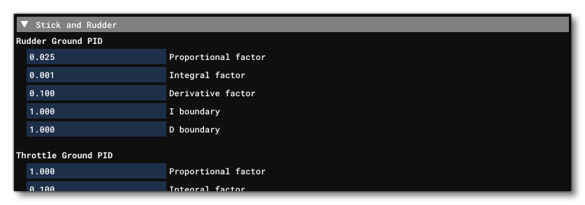
This section controls the copilot and autopilot behavior for the AI of the aircraft using the following five PID values:
- Proportional Control
- Integrator Control
- Derivative Control
- Integrator Boundary
- Derivative Boundary
Manual editing of these values is strongly suggested instead of letting the sim use the default values so that the AI behavior is more in-line with the aircraft being used. Note that the The Heading PID value is also used by non-user AI to control planes.
The following parameters are available:
- Rudder Ground PID: PID to adjust the rudder controls on the ground to stay on the centerline when taking off or taxiing using copilot and/or autopilot controls.Input is the heading error, output is the rudder control input.
- Throttle Ground PID: PID to adjust the throttle controls on ground to stay at the target speed when taking off or taxiing using copilot and/or autopilot controls.Input is the ground speed error, output is the throttle lever position.
- Brake Differential PID: PID to adjust the differential braking controls on ground to stay on the centerline when taking off or taxiing using copilot and/or autopilot controls.Input is the heading rotational speed error, output is the target delta between brakes.
- Throttle Differential PID: PID to adjust the differential throttle controls on ground to stay on the centerline when taking off or taxiing using copilot and/or autopilot controls.Input is the heading rotational speed error, output is the increase in throttle.
- Throttle PID: PID to adjust the throttle controls to stay at the target speed when in the air using copilot and/or autopilot controls.Input is the airspeed error, output is the throttle lever position.
- Pitch PID: PID to adjust the pitch controls to stay at the target pitch using copilot and/or autopilot controls.NOTE: this parameter is not used by FlyByWire aircraft.Input is the desired pitch, output is the pitch control input.
- Roll PID: PID to adjust the roll controls to stay at the target bank angle using copilot and/or autopilot controls using copilot and/or autopilot controls.Input is the desired bank, output is the bank control input.
- Heading PID: PID to adjust the bank angle to stay at the target heading using copilot and/or autopilot controls.Input is the heading error, output is the target bank.
- Vertical Speed PID: PID to adjust the pitch to stay at the target vertical speed using copilot and/or autopilot controls.Input is the vertical speed error, output is the pitch control input adjustment.
- Nav Ex1 PID: PID to adjust the heading to stay on the target navigation track using copilot and/or autopilot controls.Input is the angular deviation, output is the bank control input adjustment.
- Nav Yaw PID: PID to adjust the yaw (usually via rudder input) to stay on the target navigation track using copilot and/or autopilot controls.Input is lateral speed, output is the rudder control input.
- Glide Slope PID: PID to adjust the vertical speed to stay on the target glide slope using copilot and/or autopilot controls.Input is the angular deviation from the slope, output is the pitch control input adjustment.
- Flight Level PID: PID to adjust the pitch to stay at the target airspeed during flight level change mode using copilot and/or autopilot controls.Input is the airspeed error, output is the pitch control input adjustment.
These parameters are also explored in more detail here:
Taxi
 This section is used to define how the AI aircraft navigates the different taxiways. It has the following parameter:
- Distance To Lane Line: Sets the distance, in meters, for the aircraft from the center line of the taxiway, allowing you to position it better within its own lane. Note that setting this to 0 (or less than 0) will not position the aircraft along the center line, but instead will force the simulation to use the bounding sphere radius for the offset distance, clamped to a minimum value of 1.5m.
Tow Plane
If this section is enabled, it means the aircraft can be used as a tow plane. in which case you should set the following parameters:
- Minimum Turn Altitude: Defines the minimum AGL altitude - in ft - for the towplane to start turning after takeoff.
- Spawn Distance: The spawn distance of the towplane relative to the position of the glider, in ft.
Glider
This section is only visible if the aircraft being defined is a glider. It has the following parameters:
- Default Towplane Title: The container title of the winch SimObject that should be used for winched launches.
- Winch Spawn Distance: The initial distance of the winch on the runway relative to the position of the glider in ft.
- Allow Winch Launch: Whether this glider can be launched using a winch (checked) or not (un-checked).
- Allow Towplane Launch: Whether this glider can be launched using a towplane (checked) or not (un-checked).
- allowAutonomousLaunch: Whether this glider can launch itself without help (checked) or not (un-checked).