LANDSCAPE ELEMENTS
This section of the documentation is designed to help you create proper landscape models, specifically for Airports and Scenery, although most of the general principles outlined here are also applicable to aircraft. On this page you can find some general information about how to best create these different model elements, and you can find additional information specifically about LODs here:
Also make sure to have read over the modelling General Principles before creating anything, and if your model requires lights, then please take a moment to look over the 3Ds Max page on Lights.
Optimization Recommendations
The following are a set of recommendations that we make to ensure that your models for scenery and airports are as optimised as possible:
- Share textures between different models and model LODs.
- Remove textures you may not need at a distance, such as the normal map.
- Use appropriate texture resolutions for your textures. It is usually not necessary that all textures in a material have the same resolution.
- Use metallic/roughness/etc… material settings instead of textures when possible.
- Prefer low-resolution textures for LODs below the approximate 5% "minSize". if you really do need a texture, try to keep this as 64x64px or smaller.
- Use vertex color whenever you can! Microsoft Flight Simulator uses a single vertex format, so using vertex color is essentially free. Because of this, low-resolution LODs often do not need a texture at all.
- Minimize skinned mesh usage. Compared to regular objects, they consume a significant amount of CPU and memory in Microsoft Flight Simulator. Use them only if mesh deformation is necessary. Skinning can often be avoided on lower resolution LODs.
- Split your environment when the asset you are exporting covers an area bigger than approximately 300x300m.
- Flatten hierarchies whenever you can to reduce the node count, ideally under 300x300m.
- All scenery models (and their LODs) - with the exception of objects that aren’t important for collision - will need colliders. You should prefer using the collision shapes (rectangle, cylinder, sphere) over collidable meshes/materials. This is explained in more detail here: Collision Handling
Optimisation Example
Here a sample of an optimization process made on part of the Paris-Charles de Gaulle airport:
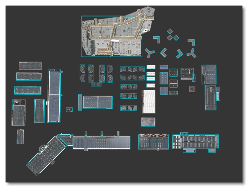 In this image, you can see an overhead view of the model, and the blue boxes represent the collision mesh (created using rectangle colliders as explained here: Simple Shape Collisions). Now consider the following image:
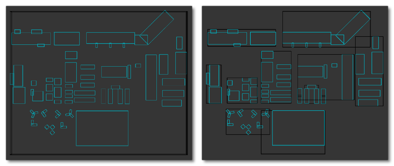
On the left the black box describes how the object was initially created as a single unique mesh of 1300x600m. However, on the right, the black boxes describe how this single object has been split into smaller objects that can now be clipped by the camera easily.
Now lets consider this following model element:
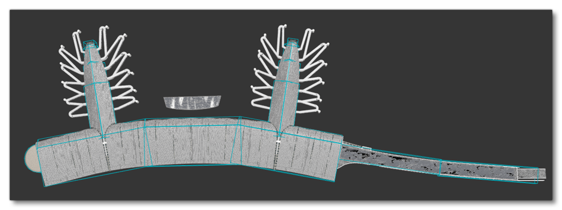
In this example element the glTF would cover an area of approximately 800m². It might be interesting to split this asset into 4 nodes and two instances, like this:
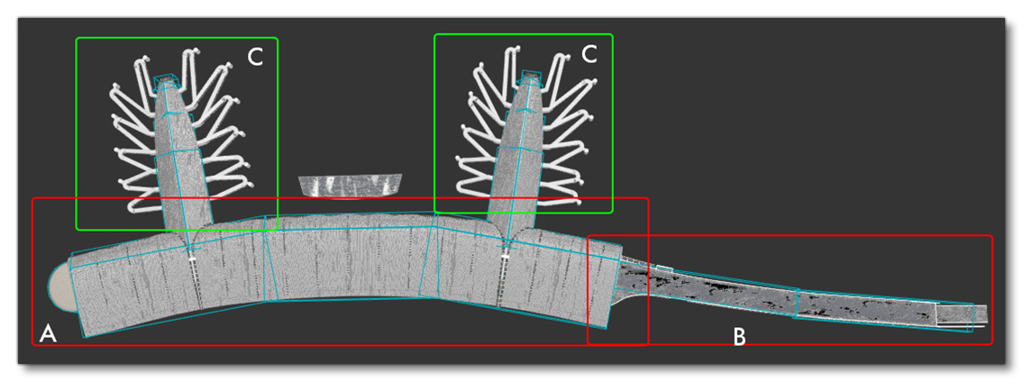
When set up like this, the meshes highlighted in green are Instances, which are essentially clone objects. When both are displayed in the camera individually they will represent 10 draw calls (5 each) and 200,000 triangles (100,000 each). However with instancing we can reduce the number of draw calls and vertices rendered by half (5 draw calls and 100,000 triangles), since all instances share the same GPU memory and their draw calls are batched as one. The down-side to this is that the instances will each require an extra node, and more nodes means more CPU overhead. So, it is important to evaluate when instances are bad, as the CPU cost introduced by the number of nodes could be higher than the GPU savings. The image below shows an example of a mesh where you can clearly see that the amount of nodes introduced by instances (for the pillars) would have a negative effect due to the sheer number of nodes required:
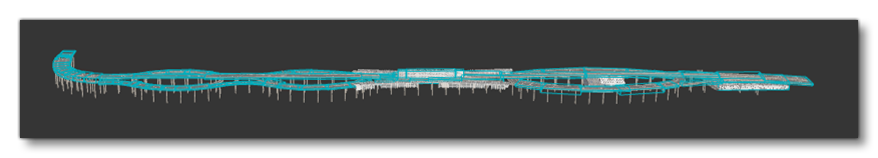 In a case like this, it would be much better to split the asset into three or four meshes, if possible.
It is also worth keeping in mind that you are not forced to keep the same node/instance structure in the subsequent LODs for the model. In fact, reducing the number of vertices and draw calls on each LOD will bring you to a point where some instances could even be merged together, and there may come a point where they can all be merged with the rest of the asset in a single mesh.