THE COCKPIT TAB

This section is used to setup the different cockpit gauges that will be used in the various glass cockpits and also in the HUD when using the drone camera. Most sections on this tab are simply used to define the values used to set a series of colours and markings within the gauge. These colours are the visual representation of various min/median/maximum - as well as warnings, errors and optimum - values.
General Values
All of the sections listed below will have a combination of the following inputs to define the different colours and levels displayed visually in the HUD/glass cockpits:
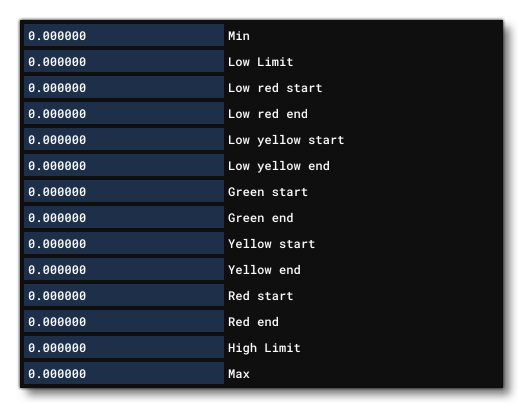 Input values will depend on the item being defined. For example, the Fuel Quantity section will require values in gallons.
-
Fuel Flow
-
Fuel Quantity
-
Fuel Temperature
-
Fuel Pressure
-
Oil Temperature
-
Oil Pressure
-
EGT Temperature
-
CHT Temperature
-
Vacuum
-
Manifold Pressure
-
Airspeed
-
Torque
-
RPM
-
Turbine NG
-
ITT Engine Off
-
ITT Engine On
-
Main Bus Voltage
-
Hot Battery Bus Voltage
-
Battery Bus Amps
-
Genalt Bus Amps
-
Coolant Level
-
Coolant Temperature
-
Gear Oil Temperature
-
Cabin Altitude
-
Cabin Altitude Change Rate
-
Cabin Pressure Diff
Attitude Indicators
 This section is used to define the characteristics of the attitude indicators on the instrument panels, where each indicator is defined in order, starting at 0 and incrementing by 1 when a new one is added. To add an indicator you click on the
 + button, and to remove one you select it then click the x button. Each attitude indicator can have one of the following settings to set the system which drives it:
- None
- Vacuum driven gyro
- Electrically driven gyro
Turn Indicators
 This section controls the glass cockpit display turn indicators. To add an indicator you click on the
 + button, and to remove one you select it then click the x button. Each turn indicator is defined in order, starting at 0 and incrementing by 1 each time a new one is added. You can then set what drives the indicator when turning or banking (or both) by selecting one of the following options:
- None
- Vacuum driven gyro
- Electrically driven gyro
Direction Indicators
 This section controls the glass cockpit display direction indicators (not including the magnetic compass). To add an indicator or an induction compass, you click on the
 + button under the section, and to remove one you select it then click the x button. Each indicator/compass is defined in order, starting at 0 and incrementing by 1 each time a new one is added.
The direction indicator requires that you select a Type for it, which can be one of the following:
- None
- Vacuum gyro
- Electric gyro
- Electro-mag slaved compass
- Slaved to another indicator
If you select the option Slaved To Another Indicator, then you also need to set the Subdirection Indicator to one of the following:
- Vacuum gyro
- Electric gyro
- Electro-mag slaved compass
The other indicator that can be added here is the Induction Compass, which can be set to the following values:
- Electric
- Anemometer driven
Airspeed Indicators
 This section controls the glass cockpit display airspeed indicators. To add an indicator, you click on the
 + button under the section, and to remove one you select it then click the x button. Each indicator is defined in order, starting at 0 and incrementing by 1 each time a new one is added.
Once an airspeed indicator has been added, it needs to have the following parameters set:
- Calibrated Airspeed - this is a scalar on the calibrated airspeed.
- Offset - this is an offset in Knots.
Altimeters
 This section controls the glass cockpit display altimeters. To add an altimeter, you click on the
 + button under the section, and to remove one you select it then click the x button. Each altimeter is defined in order, starting at 0 and incrementing by 1 each time a new one is added. The checkbox beside the altimeter is for instantiating it in the simulation.
Each altimeter also has a corresponding Altimeter Position, where you can set the position relative to the Datum Reference Point using the Lateral, Vertical and Longitudinal distance values. You can also enable the Show Gizmo option to place it visually in the simulation.
Anemometers
 This section controls the glass cockpit display anemometer. To add an anemometer, you click on the
 + button under the section, and to remove one you select it then click the x button. Each anemometer is defined in order, starting at 0 and incrementing by 1 each time a new one is added. Each anemometer needs to be placed by setting its position relative to the Datum Reference Point using the Lateral, Vertical and Longitudinal distance values. You can also enable the Show Gizmo option to place it visually in the simulation.
Magnetic Compass
 This section controls the glass cockpit display magnetic compass. To add a magnetic compass, you click on the
 + button under the section, and to remove one you select it then click the x button. Each magnetic compass is defined in order, starting at 0 and incrementing by 1 each time a new one is added. Each magnetic compass has a checkbox, which - when checked - means that it is a vertical compass, with no dip errors.
GPWS
 This section controls the cockpit GPWS. Available parameters are:
- Max Warning Height: The height below which a warning is activated, in ft.
- Sink Rate FPM: If an aircraft exceeds this rate of descent (in ft per minute) a warning is activated.
- Excessive Sink Rate FPM: If an aircraft exceeds this rate of descent (in ft per minute) an urgent warning is activated.
- Climbout Sink Rate FPM: If an aircraft starts to descend during takeoff, and exceeds this rate of descent (in ft per minute), a warning is activated.
- Flap And Gear Sink Rate FPM: If an aircraft is landing, and exceeds this rate of descent (in ft per minute) without flaps or gear extended, a warning is activated.
Throttle Levels
 This section controls the cockpit throttle levels. Each level can have the following values:
- Level Min: Set the minimum throttle percentage for each detent.
- Level Name - The name corresponding to the throttle level. Can only be one of the following:
- "REV" - reverse
- "IDLE" - idle
- "A/THR" - auto
- "CL" - climb
- "FLX" - flex
- "TOGA" - toga
Flaps Levels

This section controls the cockpit Slats and Flaps levels. Each parameter input is the slats/flaps angle (in degrees) that you want to correspond to the lever levels 1 to 10.
Misc.

This section controls certain HUD elements that will be visible when the user is in "3rd person mode" as well as the style that will be used to display them.
NOTE: For the changes made here to show up in the HUD display, you will need to first Save and Resync the aircraft, then restart the flight.
Available parameters are:
- Has G Meter: When enabled a G-meter will be displayed on the external HUD, and if disabled, none will be displayed. This meter is used to indicate how many G's the plane is taking regarding acceleration and maneuvers.
- VCockpit HUD: This can be enabled to have a "vcockpit-style" external HUD, or it can be disabled to have a "steamgauge-style" external HUD.

- High Altitude Hud: This can be enabled to display a larger altitude HUD for aircraft going above 99999 meters, or disabled for regular aircraft.NOTE: This option is only applicable when VCockpit HUD is enabled.

- HUD Airspeed Colour from Lvar: When defining your aircraft, you can select this option to set custom colours for the airspeed indicator using local variables, meaning that these colours can be changed dynamically using the using the "
L:" var identifier in Reverse Polish Notation. For this to work you need to define specifically named local variables that target the appropriate colour ranges in the indictor:
TheseL:HUD_AIRSPEED_WHITE_START // corresponds to the "white_start" parameter L:HUD_AIRSPEED_WHITE_END // corresponds to the "white_end" parameter L:HUD_AIRSPEED_GREEN_START // corresponds to the "green_start" parameter L:HUD_AIRSPEED_GREEN_END // corresponds to the "green_end" parameter L:HUD_AIRSPEED_YELLOW_START // corresponds to the "yellow_start" parameter L:HUD_AIRSPEED_YELLOW_END // corresponds to the "yellow_end" parameter L:HUD_AIRSPEED_RED_START // corresponds to the "red_start" parameter L:HUD_AIRSPEED_RED_END // corresponds to the "red_end" parameterL:vars can then be changed to adapt dynamically to the aircraft dynamics. For example, the red section of the airspeed indicator on some aircraft is used to show the stall speed, and that stall speed changes when - for example - flaps are down, meaning that this can be reflected in the airspeed indicator using these variables.
NOTE: This option is only applicable when VCockpit HUD is enabled.
- HUD Show Fuel: When checked, the HUD will display the fuel meter.

- HUD Show AoA: When checked the HUD will show the AoA gauge, with the visuals depending on the VCockpit HUD setting.NOTE: This option is only applicable when VCockpit HUD is enabled.

- HUD Show Variometer: When checked the HUD will show a variometer, with the visuals depending on the VCockpit HUD setting. Note that if the aircraft is not a glider, the variometer will always display 0.NOTE: This option is only applicable when VCockpit HUD is disabled.

- HUD Show Tachometer: When checked the HUD will show the tachometer, with the visuals depending on the VCockpit HUD setting.

- HUD Show Trim: When checked, the HUD will display the trim gauge.

- HUD Speed In Mach: When enabled, the airspeed will be displayed as a Mach value, and when disabled it will be shown in Knots.NOTE: This option is only applicable when VCockpit HUD is enabled.

- HUD Helicopter Mode: When enabled, the HUD display will change some of the elements to be more in-tune with those that you would expect for a helicopter. See the image for the HUD Show Tachometer option for an example.
NOTE: This option is only applicable when VCockpit HUD is disabled.
- Equivalent Airspeed HUD: When this is enabled, airspeed will be shown as EAS.NOTE: This option is only applicable when VCockpit HUD is enabled.

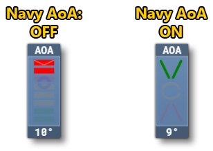
- HUD Navy AoA: This can be used to enabled or disable the navy-style AoA indicator.NOTE: This option is only applicable when VCockpit HUD is enabled.
- GPS Altimeter HUD: This can be used to enable or disable using GPS for the altitude indicator instead of the indicated altitude value (based on air pressure).NOTE: This option is only applicable when VCockpit HUD is enabled.

Takeoff Speeds

This section governs the takeoff speed indicator. It has the following parameters
- Take Off Speed Min Val:
- Take Off Speed Max Val:
- Take Off Speed Min Weight:
- Take Off Speed Max Weight: