DEFINING A FLIGHT MODEL
This tutorial covers how to define a flight model for an add-on aircraft. As such, it is expected that you already know how to use the Aircraft Editor, as we'll be referencing it in this tutorial. Also note that this tutorial focuses on flight model, aerodynamics and engine performance, but it does not detail airplane systems.
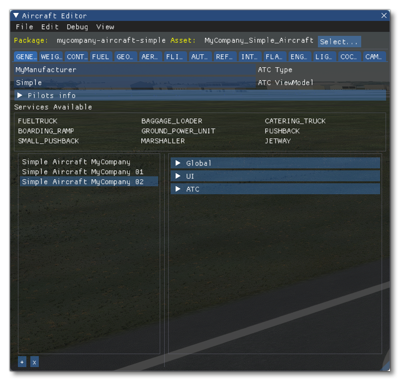
Before getting started, you should have opened the Project Editor and loaded in a package with an aircraft to edit. For this tutorial, we'll be using the SimpleAircraft sample project. Once you have done that you need to open the Aircraft Editor, which can be found under the Tools menu at the top.
NOTE: You can only edit a plane if it's a package and you have the package's project open in the Project Editor. You cannot edit the planes included in the sim.
Gathering Data
Before editing anything, however, it's important that you have all the data gathered that you will require. The new flight model in Microsoft Flight Simulator requires a lot less data to be functional than the legacy simulator Microsoft Flight Simulator X, however there is a minimum set of data necessary, and - in general - the more data you have, the easier it is going to be to make an accurate flight model.
The minimum data you will be required to have to start with is:
- Dimensions: Wing area (sqft), Wing Span (ft)
- Weight data: Maximum Weight MTOW (lbs), Empty Weight (lbs)
- Maximum lift data: Stall Speed Clean and Full Flaps (kcas)
- Engine data: Maximum Power (hp), thrust (lbs) or torque (ftlbs)
- Full power performance data: Maximum Speed (kcas), Maximum Climb Performance (ft per minute), Cruise Speed (kcas), Maximum Climb Speed Vy (kcas)
- Aerodynamic performance data: Best glide ratio, Best glide speed (kcas)
When gathering data it is important to note that:
- There are situations where not all data is available or consistent.
- Some POH may include security margins.
- To resolve performance data and make sure that they are consistent, aerodynamic formulas may be used to control data.
Finally, due to the large amounts of data required and the complexity of this data, we recommend using an calculation spreadsheet that controls performance data to store and visualise it for use in the sim:
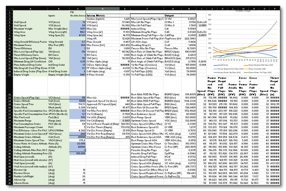
The image above was created using the spreadsheet supplied from the link below. This is designed to help with the configuration of the engines.cfg and flight_model.cfg files. It can be used to generate the required values for many of the parameters based on a small number of inputs (these inputs are marked in blue in the file):
Note that once the values are generated within the file they may need tweaked when applied to the appropriate parameters in the *.cfg files, but this should give a good base from which to start.
Setting Dimensions
The new flight model for Microsoft Flight Simulator relies on the shape of the aircraft to predict its aerodynamic behavior and we have almost entirely dropped the use of tables of data. Because of this, the correct definition of the aircraft's dimension data is of particularly importance.
NOTE: For this next step it is assumed you have loaded an aircraft into the simulator, ready to set up the flight model (see the section on How To Create An Aircraft for more information).
When setting up flight models in the Aircraft Editor, the values will be getting stored in the flight_model.cfg file, which is stored in the same folder as all the other files for the aircraft. For example you can find it here for the SimpleAircraft sample project:
<SDK ROOT>\Samples\SimpleAircraft\PackageSources\SimObjects\Airplanes\MyCompany_Simple_Aircraft\
The changes we'll be making in this tutorial will mostly be reflected in the [AIRPLANE_GEOMETRY] section but also in the [AERODYNAMICS] section.
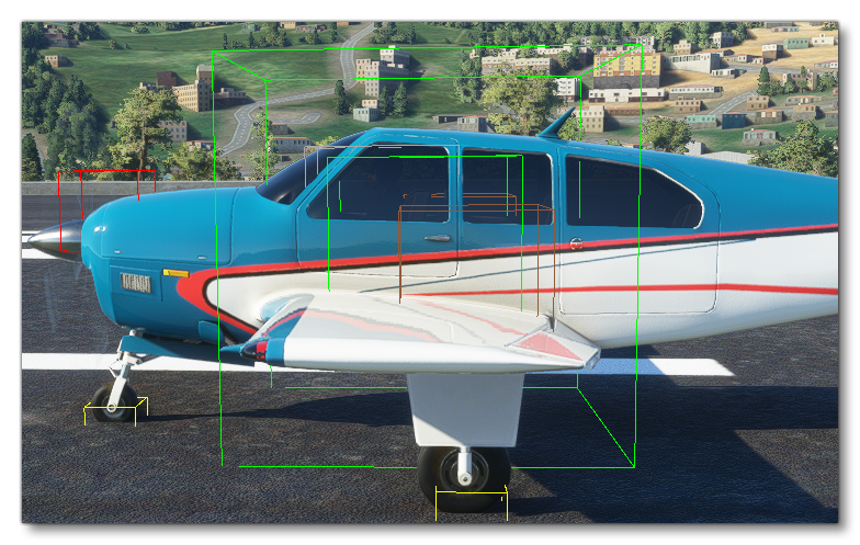
Show Sim Forces
To help visualise things, the Aircraft Editor has a number of debugging options, one of which can be used to display the actual aircraft surfaces. For that, you'd go to the Debug option in the Aircraft Editor top menu, and then select Sim Forces:
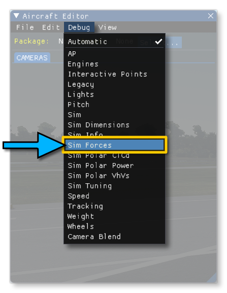
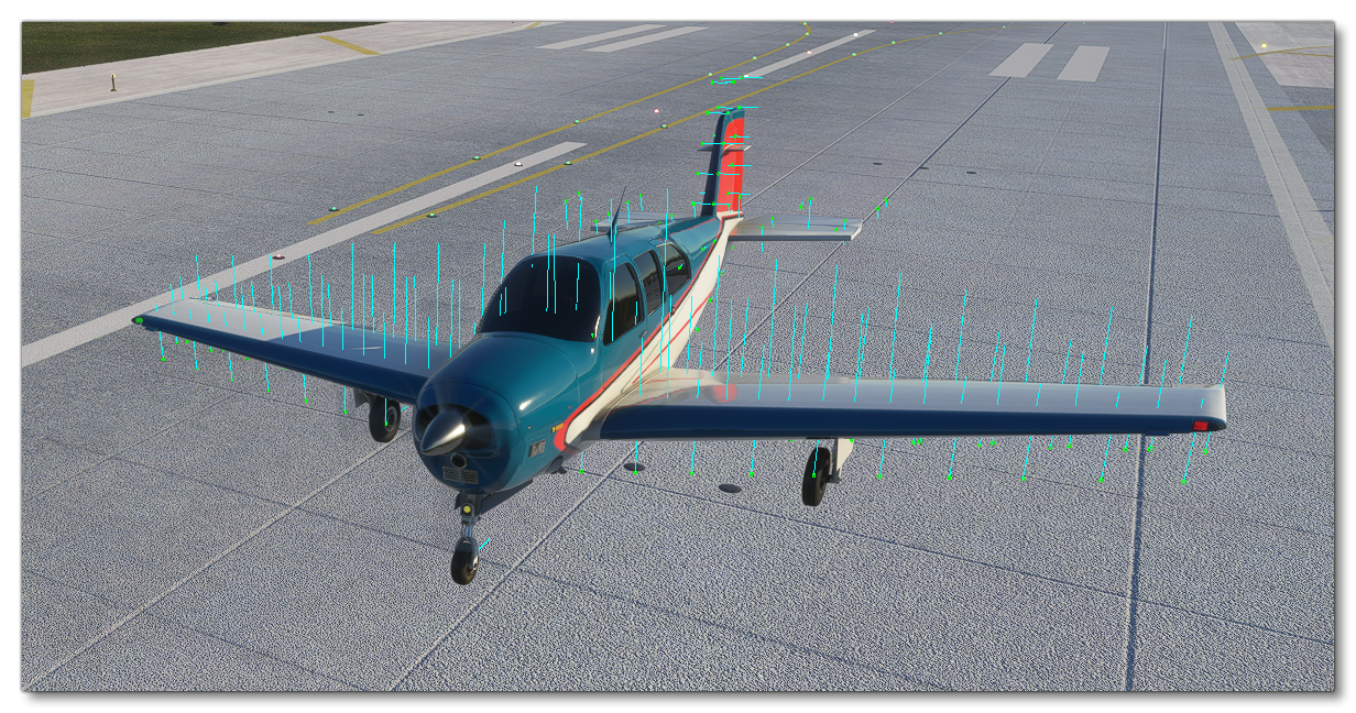
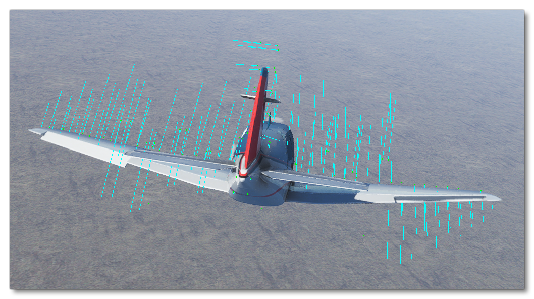
Enabling this will activates the display of the aircraft surfaces, which will be represented by a green box at their center and an aqua line that represents the force applied to that surface:
Editing The Geometry
The following sections are all related to editing the different geometries for the aircraft and this edition will be carried out in the Geometry Panel within the Aircraft Editor:
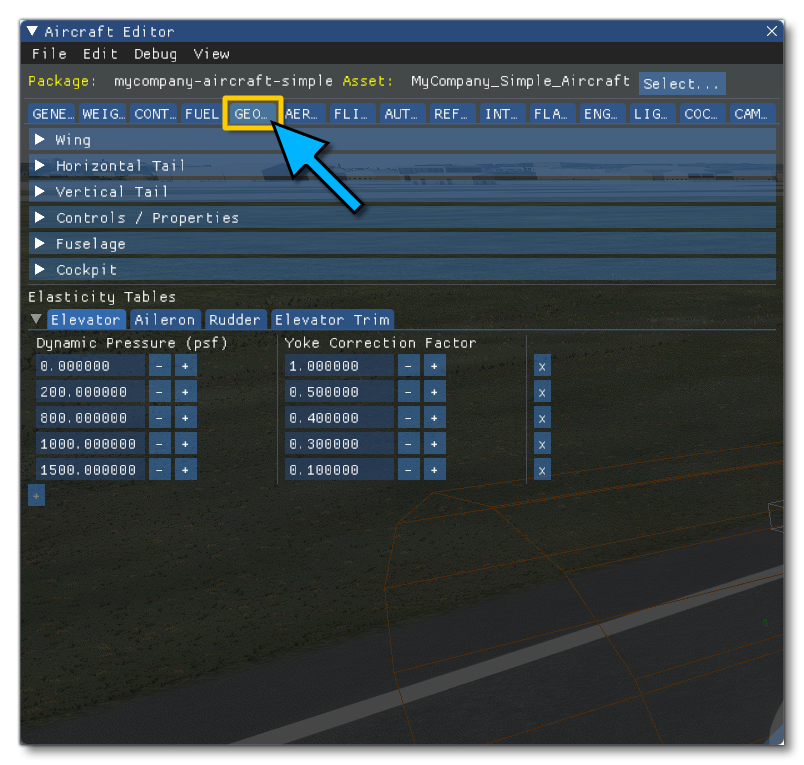
Selecting this option will also add extra debug visuals to the plane in the sim, and these can be used to visual adjust certain values when you edit the aircraft. Note that they can be disabled temporarily using the Debug > Sim Dimensions menu option, or they can be enabled when not on this panel using the same option.
Also note that when editing anything in the Aircraft Editor, you need to Save the aircraft and then Resync it so that the changes are applied in the game (both options are available from the File menu).
The Wings
We'll start by setting the wing Area and Span in the Geometry panel. These parameters are named as following in the flight_model.cfg:
wing_area = 174 ; Wing area S (SQUARE FEET)
wing_span = 36.1 ; Wing span b (FEET)
If you don't have the wingspan, you can visually adjust the number until the surface points are aligned with the ends of the wings.
Next you can set the Thickness Ratio of the wing in the Geometry panel. This is a ratio of the wing size and most wings are between 2% and 5% thick. This parameter is named as following in the flight_model.cfg:
wing_thickness_ratio = 0.05 ; Local thickness is local_chord(x) * wing_thickness_ratio, x = lateral coord
When setting the wing position, there are two lines of surface. The green points of the front surfaces need to align perfectly with the leading edge of the wings. To achieve this, you need to define the Sweep in the Geometry panel, as well as the longitudinal position. This longitudinal position is defined by positioning the aerodynamics center Aero Center Lift in the Aerodynamics panel (the panel next to the Geometry one). These parameters are named as the following in the flight_model.cfg:
wing_sweep = 1 ; Wing sweep (DEGREES)
compute_aero_center = 0
aero_center_lift = -0.05 ; Init to center
(wing_pos_apex_lon is not used, the same result is achieved with compute_aero_center when it is set to 0)
Finally, it's required that you position the wing vertically and adjust its size by adjusting the vertical position (Pos Apex Vert in the editor), as well as the Dihedral (in degrees) and the Root Chord (measured in ft). These parameters are named as follows in the flight_model.cfg:
wing_pos_apex_vert = 2.65 ; Vertical (y) position of wing apex w.r.t reference datum (FEET)
wing_dihedral = 2 ; Dihedral angle Lambda (DEGREES)
wing_root_chord = 6.5 ; Wing root chord croot (FEET)
At this stage, if you have additional data about the wings, you can set them now. If you don't you can set default values such as the following. These values mostly impact the handling such as Camber, Incidence, Twist or Oswald Efficiency Factor (some of these are explained in more detail towards the end of this page). These parameters are named as follows in the flight_model.cfg:
wing_camber = 1 ; (DEGREES)
wing_incidence = 1.5 ; Wing incidence (DEGREES)
wing_twist = -3 ; Wing twist epsilon (DEGREES)
oswald_efficiency_factor = 0.77 ; Wing Oswald efficiency factor (non dimensional)
At this stage, when seen from the side, you should have the front line for the wing surfaces aligned with the leading edge of the wing, and the rear line of the wing surfaces at the middle of the wing. This way, the sum of the aerodynamics forces will be aligned at 25% MAC.
The Fuselage
To adjust the fuselage surface positions and their dimensions to the visual fuselage of the aircraft model, you need to edit the following parameters: Center, Length and Diameter (measured in ft). These parameters are named as follows in the flight_model.cfg:
fuselage_length = -1 ; Nose to tail (FEET)
fuselage_diameter = 2.5
fuselage_center_pos = -6, 0, 0.3
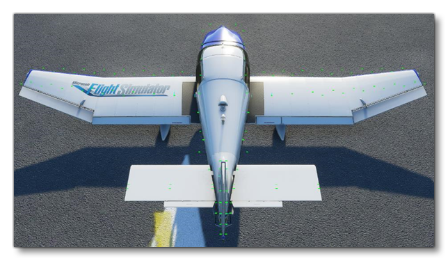
Once this is done, you should see the fuselage surfaces adjusted:
The Horizontal Tail
To adjust the horizontal tail's vertical and longitudinal position with the parameters Pos Lon and Pos Vert (in ft). These parameters are named as follows in the flight_model.cfg:
htail_pos_lon = -17.3 ; Longitudinal (z) position of horizontal tail w.r.t reference datum (FEET)
htail_pos_vert = 0.5 ; Vertical (y) position of horizontal tail w.r.t reference datum (FEET)
You'll also want to adjust the horizontal tail Thickness Ratio. This parameter is named as follows in the flight_model.cfg:
htail_thickness_ratio = 0.025 ; Local thickness is local_chord(x) * htail_thickness_ratio, x = lateral coord
Next adjust the horizontal tail surface by adjusting the Area and the Elevator Area (the second one is in Controls / Properties section). Each area should cover the exact area of that control surface, if available. If not available, you can adjust it visually so that the surface points cover the area well enough. If the aircraft only has an elevator and no horizontal stabilizer,the horizontal tale area (htail_area) should be set to zero. These parameters are named as follows in the flight_model.cfg:
htail_area = 17 ; Horizontal tail area (SQUARE FEET)
elevator_area = 17 ; Elevator area (SQUARE FEET)
Finally, you'll want to adjust the Sweep and Span of the horizontal tail based off of the data you have or using a visual alignment to the model, and in the the flight_model.cfg they are:
htail_span = 11 ; Horizontal tail span (FEET)
htail_sweep = 10 ; Horizontal tail sweep angle (DEGREES)
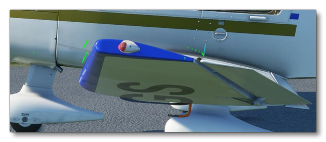
You'll want to leave the horizontal tail Incidence (htail_incidence in the flight_model.cfg) at zero for the moment, this value will be used to set the default trim of the aircraft.
If you have done it all correctly, you should see the surfaces aligned to the horizontal tail:
The Vertical Tail
To adjust the vertical tail's vertical and longitudinal position you need the parameters Pos Vert and Pos Lon.
You'll find them in the flight_model.cfg file as:
vtail_pos_lon = -17 ; Longitudinal (z) position of vertical tail w.r.t reference datum (FEET)
vtail_pos_vert = 3 ; Vertical (y) position of vertical tail w.r.t reference datum (FEET)
Now you would adjust the vertical tail Thickness Ratio, which has the following parameter in the flight_model.cfg file:
vtail_thickness_ratio = 0.033 ; Local thickness is local_chord(x) * vtail_thickness_ratio, x = lateral coord
You would next want to adjust the vertical tail surface by adjusting the vtail Area and the Rudder Area (the second one is in Controls / Properties). Each area should be the exact area of the control surface, if you have the data available. If you don't have that data then you can visually adjust the values so that the surface points cover the area well enough. The flight_model.cfg has these parameters as:
vtail_area = 15 ; Vertical tail area (SQUARE FEET)
rudder_area = 15 ; Elevator area (SQUARE FEET)
Finally, adjust the Sweep and Span of the vertical tail based on the data you have or using visual alignment to the model. These parameters are named as follows in the flight_model.cfg:
vtail_span = 4.4 ; Vertical tail span (FEET)
vtail_sweep = 35 ; Vertical tail sweep angle (DEGREES)
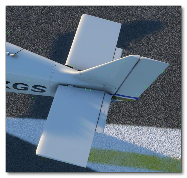
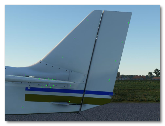
After this step, you should see the surfaces aligned to the vertical tail:
Positioning Wheels And Contacts Points
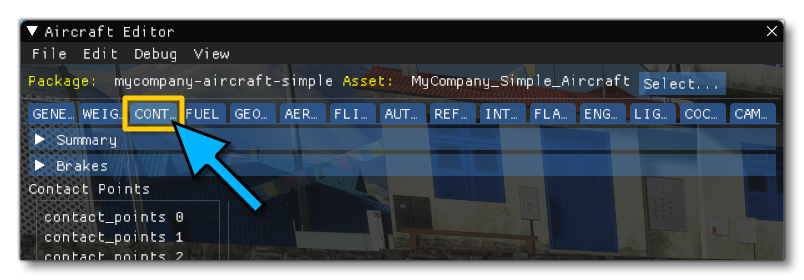
Even though the contact and friction models of Microsoft Flight Simulator have been completely changed compared to FSX, contact points are defined exactly like they were in the past. These values can be set in the Aircraft Editor from the CONTACT/BRAKES panel:
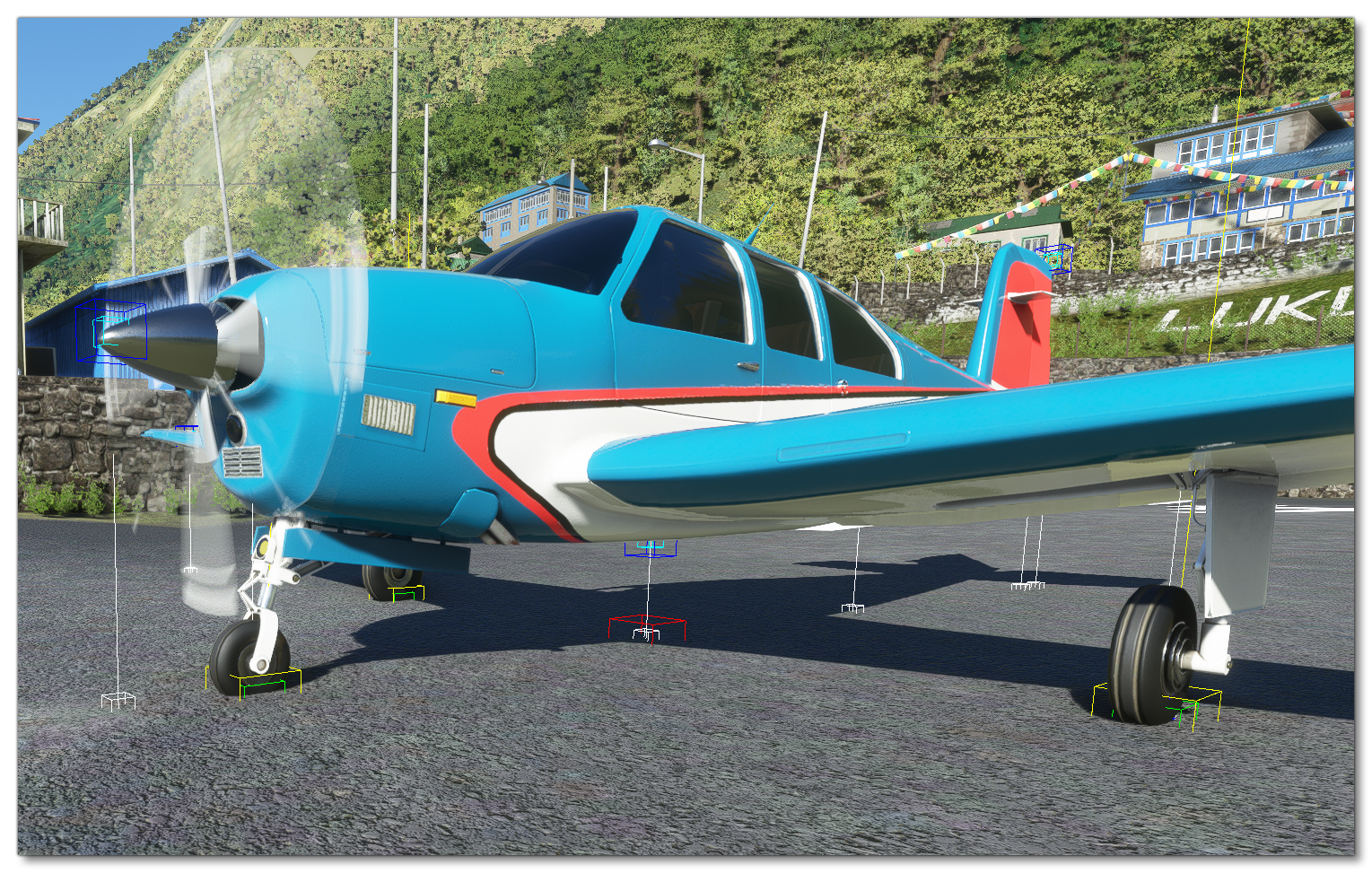
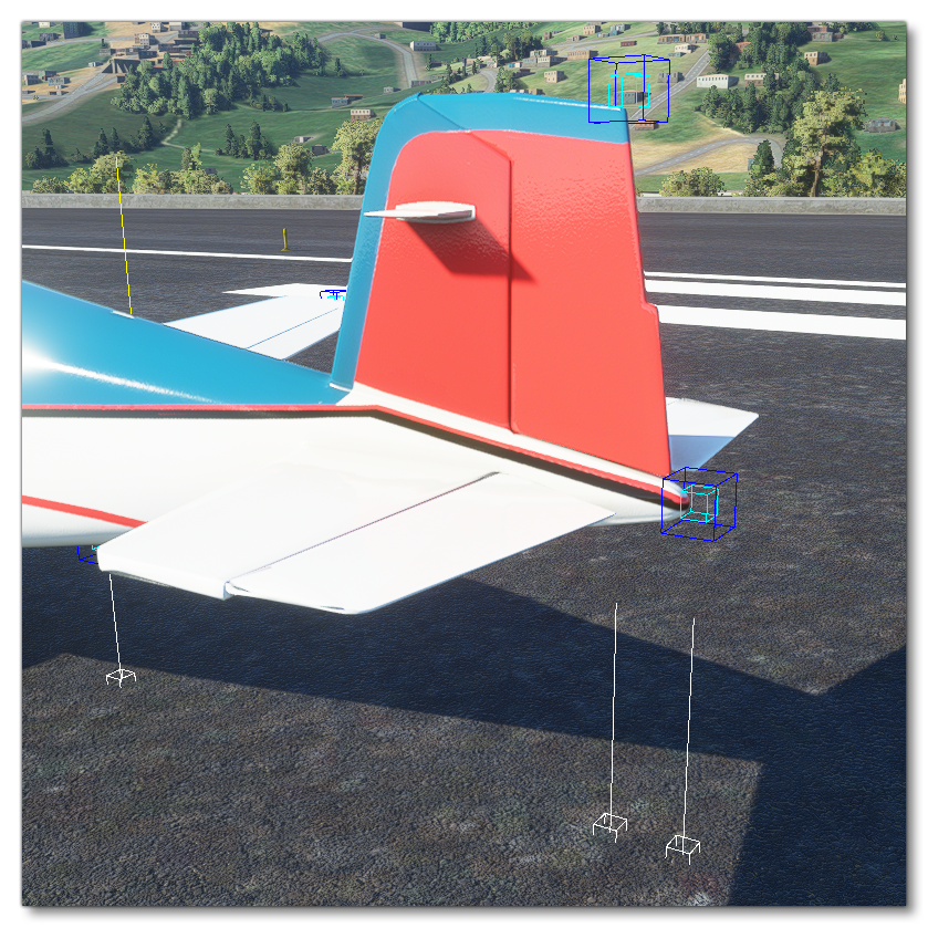
By default when you select this panel the sim should display the different contact points using a blue box and also show their projection to the nearest surface using a white line and a white box (the line represents the surface normal). Wheels will also be represented in this view as yellow boxes with an additional green box for the contact force:
NOTE: If you do not see this information when selecting the panel, or you wish to toggle it on or off, you can use the Aircraft Editor Debug menu and select/deselect Wheels.
In the Aircraft Editor, on the left, you'll see all the defined contact points for the aircraft, and you can add or remove contact points using the [+] and [-] buttons at the bottom of the editor. If you are using a new custom model then you'll need start by adding in the contact points one at a time and using the following parameters to position the wheels and set other information about them:
- Type - Sets the type of contact point.
- Pos - The position of the contact point/wheel relative to the center point of the aircraft.
- Crash velocity - The maximum velocity at which the wheel will work before being considered a crash.
- Brake - The brake type for the wheel.
- Wheel radius - The wheel radius.
- Wheel steering angle - The maximum angle the wheel can be turned when steering.
- Static compression - This sets the landing gear compression when the airplane is on the ground with all the weight compressing the gears.
- Max to static compression - This sets the maximum to static compression ratio. The higher this ratio is, the "stiffer" the suspension will be, but the higher the loads it can absorb before hitting maximum travel.
- Damping ratio - This represents a ratio of how much energy is lost upon impact.
- Extend time - The time required for the wheel to be extended from the aircraft.
- Retract time - The time required for the wheel to be retracted into the aircraft.
- Sound ID - The ID of the sound effect to use.
- Airspeed retr. - The airspeed at which the landing gear needs to be retracted.
- Airspeed. dam. - The airspeed at which the landing gear will be damaged if not retracted.
- Exponential Constant - This allows you to change the spring reaction curve.
These parameters are all set using a single entry in the [CONTACT_POINTS] section of the flight_model.cfg file, which follows the following format:
point.number = class, long_pos, lat_pos, vert_pos, crash_velocity, braking_enum, wheel_radius, steer_angle, static_compression, max_to_static_compression_ratio, dapting_ratio, extend_time, retract_time, sound_enum, airpseed_limit, airspeed_damage, exponential_constant
Below is an example with some actual values:
point.0 = 1, 1.1, 0, -3.44, 750, 0, 0.5, 10, 0.3185, 2, 0.75, 0, 0, 0, 0, 0
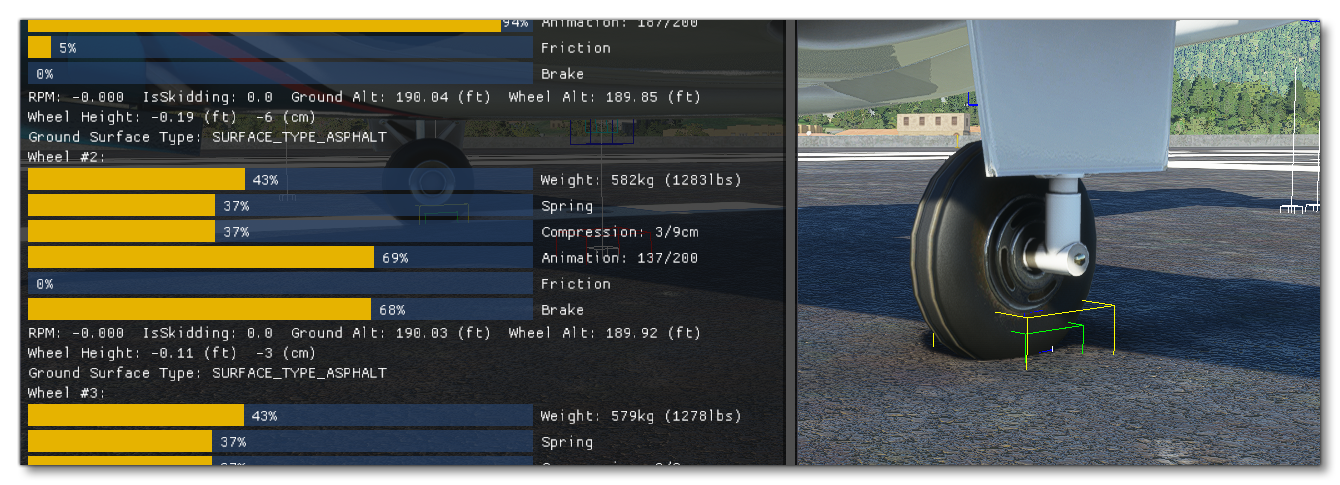
You'll have noticed that an additional debug window opened when you selected the Contact/Brakes panel:
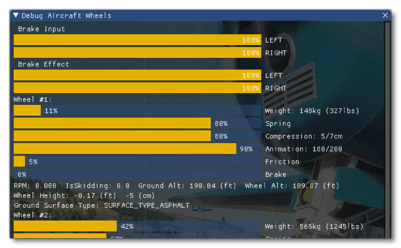
You can use this window to help understand the results of the data set. Note that the contact surface between a wheel and the ground is a surface, but we only simulate a point. In order to give the best stability to the plane, we recommend that the wheel points are positioned at the exterior limits of the wheel's triangle. The compression parameters are also displayed in the debug window. We recommend adjusting the compression ratios and distances so that the suspensions are compressed between 30% and 50% when standing on the runway such that the plane has the correct pitch when standing. A pitch that is too high or too low will negatively impact stability during take-off and landing.
A correctly positioned wheel contact point should look something like this:
You can then position the other contact points so that they are aligned correctly. These points are set similarly to the wheels but most of the fields will be set to zero. In the flight_model.cfg file they would be defined like this:
point.3 = 17, 3.6, 0, 0.9, 1, 0, 0, 0, 0, 0, 0, 0, 0, 0, 0, 0
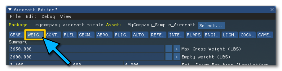
Setting Aircraft Weight And Weight Distribution
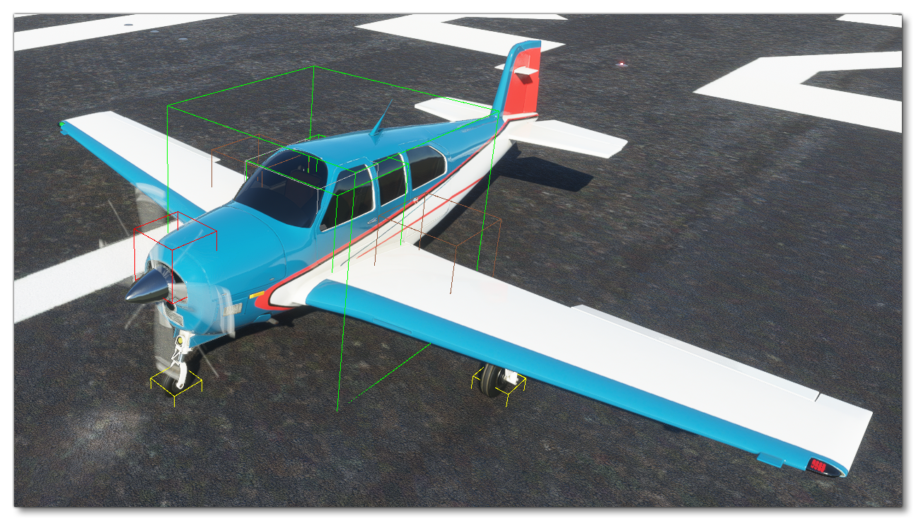
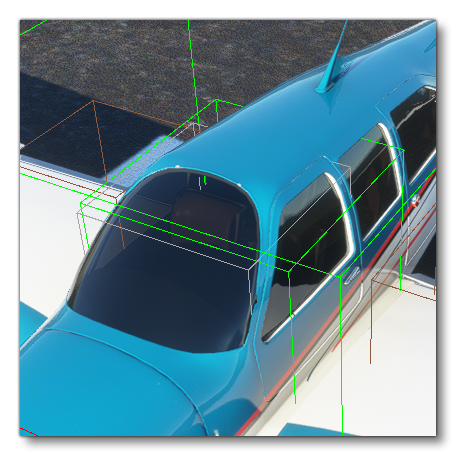
The definition of weight distribution has not changed in Microsoft Flight Simulator compared to FSX, but as this is a key factor in the flight model, we have developed new tools to helps you better position weights and balance them. To set weights and see distribution information you can open the WEIGHT AND BALANCE panel in the Aircraft Editor:
By default, clicking this will change the debug visualisation to show basic shapes for weight and distribution. This can be toggled on and off using the Debug menu in the Aircraft Editor and selecting Weight. In this visualisation, the empty CG will be displayed as a two green boxes, the pilots will be represented by grey boxes, fuel tanks will be brown boxes and the engines will be represented as red boxes.
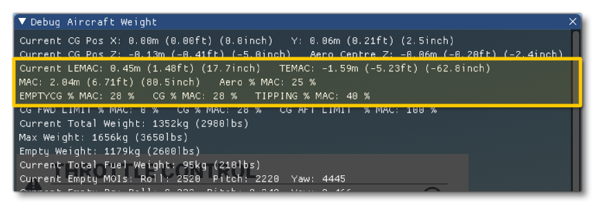
When you open this panel, two other debug windows will open with much more precise data regarding the Weight and the Sim Tuning.
Aircraft Weight And CG
The minimum information required here would be the Max Gross Weight and the Empty Weight. These parameters are named as follows in the flight_model.cfg, in the [WEIGHT_AND_BALANCE] section:
max_gross_weight = 2558 ; Max weight, (LBS)
empty_weight = 1691 ; Empty weight, (LBS)
You should also define the position of the CG of the empty plane through Empty Weight CG position, relative to the Datum Reference Point. In the flight_model.cfg, this would be in the [WEIGHT_AND_BALANCE] section as shown in the following example:
empty_weight_CG_position = -3, 0, 0 ; Position of airplane empty weight CG relative to reference datum (FEET), z, x, y
Data is not always available to position the empty CG on an aircraft, but the correct positioning of the CG is critical for the plane to fly normally. Here are a few tricks to help with setting this up:
- The lateral (x) component of the empty CG position is usually zero.
- The vertical (y) component of the empty CG is usually located close to the middle of the fuselage on the vertical axis. For a high wing, it will be a little higher, for a low wing, a little lower.
- To position the longitudinal (z) component of the empty CG, the best is to use the % MAC. If that information is available, use it directly. If not, usually, the empty CG will be located at around 20% MAC. The % MAC of the empty CG is displayed in the debug window of the weight debug screen. A %MAC outside of the 10% to 35% range may result in an uncontrollable aircraft:
Pilots And Other Load Stations
Also in the WEIGHT AND BALANCE panel, you can set the position of the pilots and other load stations - such as luggage - in the Station Load Factory Mass section, at the bottom of the panel. As with other weight and balance options, you can position these extra weights using Long, Lat and Vert position (in ft) relative to the center of the model, and also give them a name and a mass (mass here is measured in lbs). Note that you can add entries into this list using the + button at the bottom, if required. These parameters are named as follows in the flight_model.cfg, in the [WEIGHT_AND_BALANCE] section:
station_load.0 = 170, -3.7, -1.1, 0.8, Pilot, 1
station_load.1 = 170, -3.7, 1.1, 0.8, Copilot, 2
station_load.2 = 0, -6.2, -0.7, 0.8, Passenger Left, 3
station_load.3 = 0, -6.2, 0.7, 0.8, Passenger Right, 3
station_load.4 = 0, -8, 0, 0, Cargo, 6
These load stations will be represented as grey boxes in the debug visualisation to help correct positioning:
Fuel
Setting the Fuel capacity and position can be done from the FUEL panel in the Aircraft Editor:
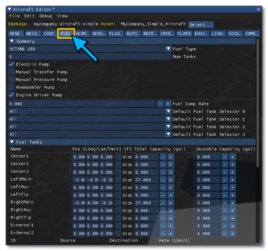
The number of fuel tanks for every model is fixed and listed in this window, and you simply need to set the properties for those that are appropriate to the aircraft being modeled. Leave those that are not required all set to 0. To position them you simply change the Long, Lat and Vert position (in ft) relative to the center of the model, and you can also set the Total Capacity and Unusable Capacity (in Gallons). These values can also be edited in the flight_model.cfg file [FUEL] section, as shown in this example:
LeftMain = -3.6, -3.1, 2.9, 28, 1.5 ; For each tank: Tank position (z longitudinal, x lateral, y vertical in ft), total fuel capacity (GALLONS), unusable fuel capacity (GALLONS)
In the debug visualisation it is shown by the position of the brown boxes representing the fuel tanks on the aircraft:
Engines
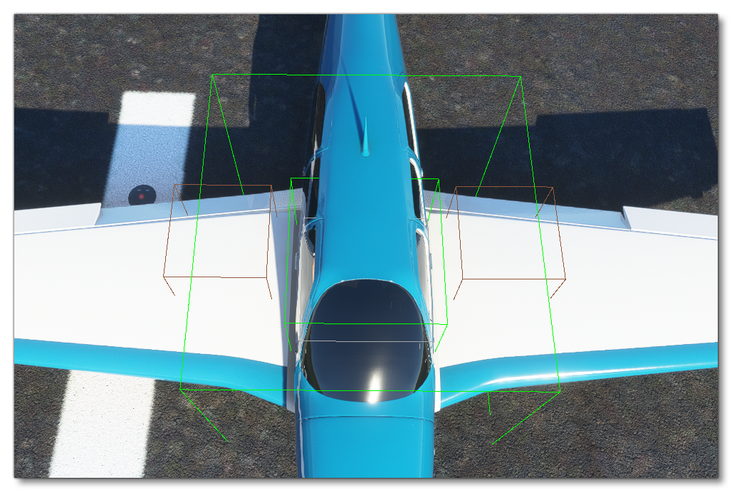
Another important part of balancing is the correct placing of the engines. This is achieved from the ENGINE panel of the Aircraft Editor, editing the Long, Lat and Vert position (in ft) relative to the center of the model:
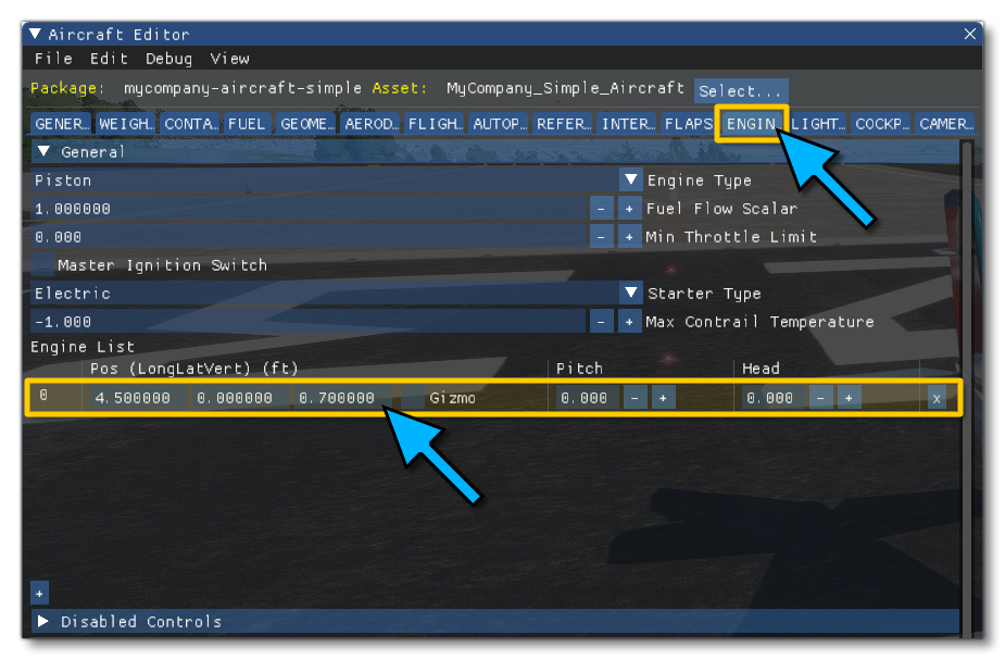
Note that you can add engines by clicking the + button at the bottom, and remove them by clicking X button to the right of the engine on the list.
To edit the engines manually, you need to open the engines.cfg file, then go to the [GENERALENGINEDATA] section, then change what's there or add extra data, something like in the following example:
Engine.0 = 3.5, 0, 1
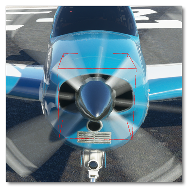
To help with correct positioning, the engines are represented by red boxes in the debug visualisation. The red box should be positioned where the thrust force will apply, generally at the center of the propeller or at the exhaust of a jet engine:
Define Moments Of Inertia
Now that you've set everything that influences the weight of the aircraft and the distribution of weight over the its volume, it is time to set the empty aircraft MOIs in the WEIGHT AND BALANCE panel using the parameters:
- Empty Weight Pitch MOI
- Empty Weight Roll MOI
- Empty Weight Yaw MOI
- Empty Weight Coupled MOI
These parameters use the Slug sqft unit, and you can find them in the flight_model.cfg, under the [WEIGHT_AND_BALANCE] section, eg:
empty_weight_pitch_MOI = 2457 ; Empty pitch moment of inertia, Jxx (SLUG SQ FEET)
empty_weight_roll_MOI = 2548 ; Empty roll moment of inertia, Jzz (SLUG SQ FEET)
empty_weight_yaw_MOI = 4389 ; Empty yaw moment of inertia, Jyy (SLUG SQ FEET)
empty_weight_coupled_MOI = 100 ; Empty transverse moment of inertia, Jyz (SLUG SQ FEET)
If you have the data available for these setting then you should always use it, but if not, we have developed a tool that computes the MOIs based on the dimensions and geometric shape of the aircraft, now that you have defined everything. You can find the results of these MOI calculations in the Weight ANd Balance Debug Window that opens when you select that panel:
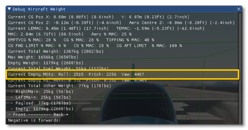
If you don't have exact data available for the aircraft, we recommend using the information from this window instead.
Base Aerodynamic Parameters
The use of geometric information and a surface-based simulation reduces the need for aerodynamic performance data to the strict minimum. However, it is impossible to get exactly the right values and performance just based on geometry. Each aircraft has little imperfections - forms and shapes that are too small and complex to be perfectly simulated in real time - and for that reason we use a normalization system. By entering a very small set of performance values you can define the target performance you need for the aircraft. Then, in order to achieve the performance values you've entered, the aircraft is run through a virtual wind tunnel in real time and the sim performs 100 adjustment iterations to the surface aerodynamic parameters.
To set the base aerodynamics parameters you need to go to the AERODYNAMICS panel of the Aircraft Editor:
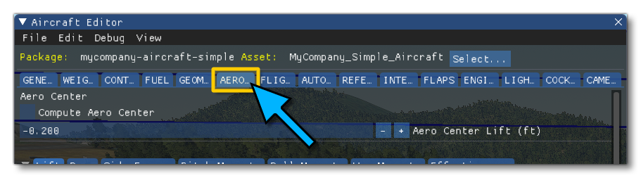
These parameters are also available to edit in the section [AERODYNAMICS] of the flight_model.cfg file.
Drag
To start with we'll look at the Drag tab of the Aerodynamics panel. Here we'll be setting the Zero Lift Drag (or Cd0), which is the minimum aerodynamic drag the aircraft produces (this is in the Base Constants section). This needs to be set in clean, cruise configuration, with the landing gear excluded. If the landing gear can be retracted this will be the cruise zero lift drag of the aircraft. If the landing gear cannot be retracted, this will be the cruise zero lift drag minus the gear drag. This parameter is named as follows in the flight_model.cfg, under the [AERODYNAMICS] header:
drag_coef_zero_lift = 0.0327 ; The zero lift drag polar
If you know this value exactly, then use it. If not, this value is usually of around 0.02 to 0.025 for an aircraft with a glide ratio above 15, 0.03 to 0.04 for aircraft with glide ratios of about 10, and up to 0.1 for some slow bush planes with very low glide ratios.
Next you'll also want to enter the Gear Drag Ratio value into the editor, which - in the flight_model.cfg - is under the [AERODYNAMICS] section and it looks like this:
drag_coef_gear = 0.006836
If you know this value exactly, then use it. If not, gear drag is usually between 0.005 and 0.01.
After setting these values, you'll need to set the Cl0 value, which is the lift the aircraft produces when the drag is minimum.
NOTE: This parameter is a new addition to the parameter set and is not in the Aircraft Editor, so you are required to set it in the flight_model.cfg directly.
The legacy simulator used this simplified drag formula:
Cd = Cd0 + k * Cl²
The problem with this simplified formula is that it only allowed you to simulate planes that had their minimum drag when the lift coefficient was zero, and this is rarely the case. In clean configurations, many planes have their minimum drag at lift coefficients of around 0.1 and in full flap configurations, that parameter can go up to 0.4. The new system is normalized to a drag polar that follows this more accurate formula:
Cd = Cd0 + k * (Cl - Cl0)².
So we need to define Cl0, which is the lift coefficient that is generated when the plane produces minimum drag, defined in the flight_model.cfg as:
lift_coef_at_drag_zero = 0.1
If you know this value exactly, use it. If not, this value is usually of around 0.1 in clean configuration.
Now we need to define how lift impacts drag, so that the wind tunnel normalization system can adjust the surfaces to match the right drag polar. This is achieved through the legacy Oswald Efficiency Factor:
oswald_efficiency_factor = 0.77 ; Wing Oswald efficiency factor e (non-dimensional)
There is also a new factor that allows you to scale things up or down depending on the polar curve:
induced_drag_scalar = 1.5
If you know the Oswald coefficient of the plane then use it. If not, the Oswald is usually between 0.7 and 0.8, with 0.75 being a good default value. The induced drag scalar is usually a little above 1. Indeed, because we use the advanced drag polar formula, our drag is proportional to (Cl - Cl0)² and therefore smaller than the simplified drag that was proportional to Cl². Because of that, we need to have a larger k and therefore an induced drag scalar larger than 1. If you have this value, use it. If not, a value between 1.2 and 1.5 is usually fine. If this value is above 1.5, the plane will generate a lot of drag at slow speed, and if the value is closer to 1, it will glide very easily at slow speeds.
Lift
Similarly to drag, lift is calculated based on the geometry and shape of the aircraft. But because the surfaces and shape of the aircraft are never perfect, we, again, use our wind tunnel normalization process to adjust the aerodynamic parameters of the surfaces so that they produce the right lift.
To define the lift curve, we use a sub section of the legacy lift table. The only parameters that are key now in this table are the lift coefficient at an angle of attack of zero, and the maximum clean lift coefficient at the stall angle of attack. You can set these values from the Lift tab of the AERODYNAMICS panel in the aircraft editor, scrolling down to the AoA Tables section:
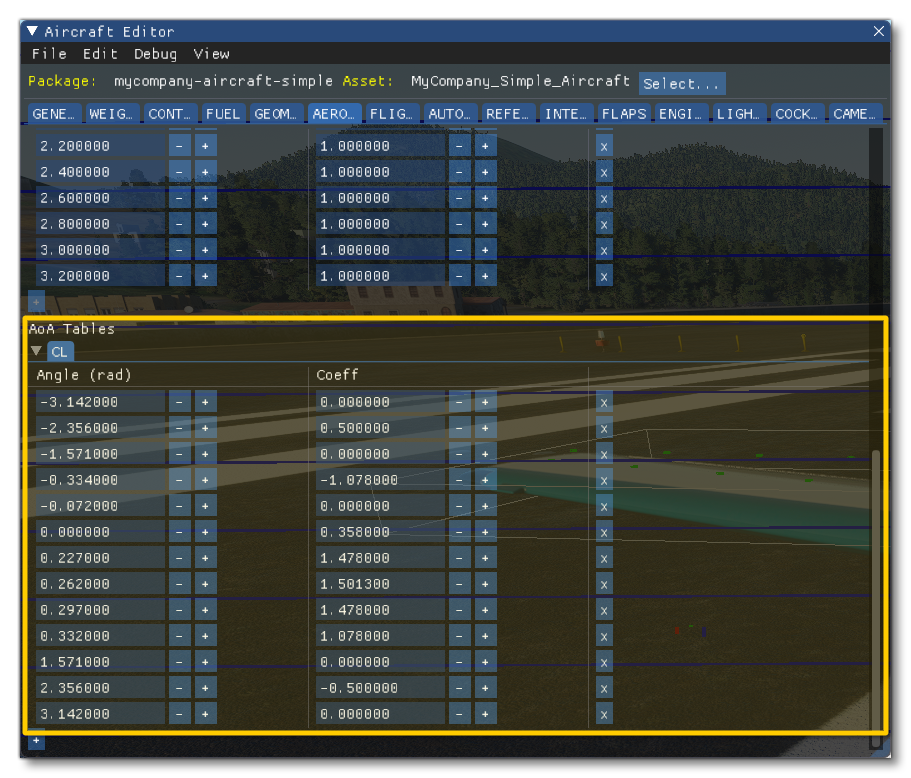
You can also edit the table directly in the in the flight_model.cfg under the [AERODYNAMICS] section as a comma separated list where each entry is <angle>:<Coefficient>, eg:
lift_coef_aoa_table = -3.15:0, -0.8:-1.029, -0.4:-0.789, -0.2:-0.572, -0.1:-0.375, 0:0.257, 0.2:1.408, 0.23:1.474, 0.26:1.5416, 0.29:1.528, 0.31:1.466, 0.4:0.842, 0.8:1.046, 3.15:0
These are the only ones that are used for the wind tunnel normalization of the new aerodynamics model. The other values are necessary only for compatibility with the legacy simulation and can be ignored at this stage. So a simplified table at this stage could look like this:
lift_coef_aoa_table = -3.15:0, -0.8:-1.029, 0:0.257, 0.26:1.5416, 3.15:0
To help understand the lift and drag curves of the aircraft, you can enable the Sim debug option in the Aircraft Editor:
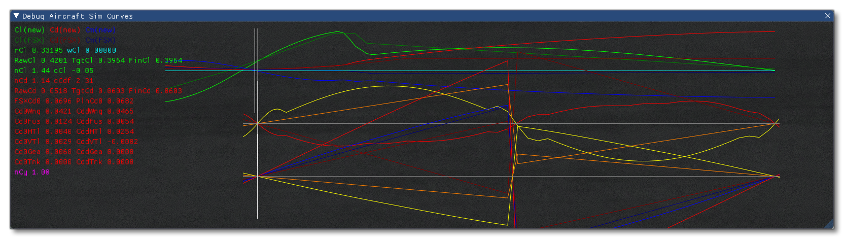
IMPORTANT! The new surface-based simulation in Microsoft Flight Simulator functions in full 3D and simulates the airflow over the aircraft, whatever its direction. However, we only normalize the aircraft performance to the airflow moving on the longitudinal axis, with AoA between zero and 15°. For airflows that would move 100% laterally or vertically, we use standard aerodynamics surface definitions that cannot be changed at this stage. These situations however are either impossible or extremely rare in normal flight and do only have some importance for aerobatics.
Control Surfaces
Now your aircraft has everything it needs to fly. We recommend that you start from an example aircraft that already had a similar engine, so that you should even be able to take off. The exact power and performance is unimportant at this stage. You can also press the F10 key, to instantly gain 1000FT and glide the aircraft.
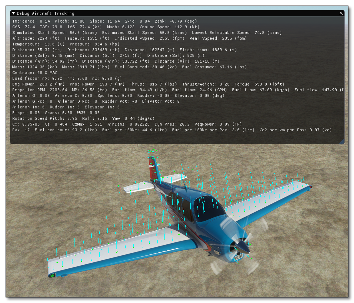
For this step, we recommend enabling the general debug of aircraft flight data as well activating the display of the surfaces and the forces acting on them. These are activated from the Aircraft Editor Debug menu, selecting Tracking and Sim Forces respectively. With both debug tools on screen, you should see something like the following:
With experience we have found that the easiest and quickest order to define the control surfaces and general stability is: Aileron > Rudder > Elevator, and so that's the order that we'll explain them in this document. Most of the following sections can be edited from a combination of the GEOMETRY and FLIGHT TUNING panels in the Aircraft Editor, or under the [AIRPLANE_GEOMETRY] and [FLIGHT_TUNING] sections of the flight_model.cfg.
Ailerons And General Stability
We recommend starting with aileron control as it will allow to set the general stability of the aircraft. Start by defining the Aileron Area (sqft), which has the following setting in the flight_model.cfg file:
aileron_area = 10 ; Elevator area (SQUARE FEET)
If you have this exact data, use it. If you don't have this data, you can set a value that is in the same order of magnitude as the rudder or elevator surface areas.
Next you'd set the set the Aileron Up and Aileron Down limit angles (in degrees), which have the following settings in the flight_model.cfg file:
aileron_up_limit = 20 ; Aileron max deflection angle (DEGREES)
aileron_down_limit = 15 ; Aileron max deflection down angle (absolute value) (DEGREES)
If you have this exact data, use it. If you don't have this data, you can set the up limit to 20 and the down limit to 15.
NOTE: This type of data is rarely found in a POH but can be found on the website of the FAA.
Now you need to define what percentage of length of the wing is covered by the ailerons. Usually, this distance, plus the percentage of the length of the wing covered by flaps, is equal to approximately 100% of the total length. This can't currently be set in the editor so you need to add or edit the following line in the flight_model.cfg file:
aileron_span_outboard = 0.7
Next you can define how much control you want to be applied to the ailerons, depending on the speed of the aircraft. This is a table that defines the ratio of aileron control depending on the amount of dynamic air pressure, and can be set by scrolling to the bottom of the GEOMETRY panel to the section on Elasticity Tables and selecting the Aileron tab. If you are editing the flight_model.cfg file, you'd use something like the following:
aileron_elasticity_table = 0:1, 25:1, 50:0.75, 75:0.5, 100:0.33
The current dynamic air pressure is displayed on the debug screen to help adjust the aileron control depending on the current speed:
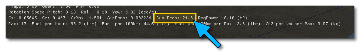
At lower speeds, up to climb speed, this ratio is usually 100% and it starts decreasing at cruise speed and can reach values close to zero when the plane is flying over speed, above the red bar (complete loss of authority).
Now it is time to set the aircraft roll stability. Based on the dimensions and geometric definition of the aircraft, our surface based aerodynamics simulation automatically calculates the minimum rotational air friction. But because a real airplane is not made of perfect surfaces with a perfect shape, real rotational friction is always going to be higher.
So, to adjust the rotational friction you can go to the Flight Tuning panel now to edit the Roll Stability setting, or edit the flight_model.cfg file directly like this:
roll_stability = 0.1
You need to enter a value that is higher than zero for backwards compatibility with the legacy flight model, and you can enter 0.01 - for example - if you want only the minimum rotational friction. If the plane has more roll inertia, you can enter higher values.
Now the final adjustment needs to be made to define the maximum authority of our ailerons. This will be done to achieve the maximum roll speed that is possible with the aircraft at a given speed, and is done from the Aileron Effectiveness setting in the Flight Tuning panel, or from the following setting in the flight_model.cfg file:
aileron_effectiveness = 1.25
If you have this value, then you should use it. Otherwise, most aircraft can achieve maximum roll speeds of more than 30 degrees per second. For a GA aircraft 30 to 60 degrees per second is a good start. The above parameter allows you to scale the aileron authority up or down depending on your needs.
Note that the current roll speed can be found in the debug window Aircraft Tracking debug window. In the image below you can see an example of the forces that are being applied as a result of the aileron angles when the aileron angles are maximal:
Rudder
You can now define the Rudder Area (sqft) if it's not already been done from the GEOMETRY panel. This has the following setting in the flight_model.cfg file:
rudder_area = 6.8 ; Rudder area (SQUARE FEET)
If you have this exact data, use it. If you don't have this data, you can set a value that is in the same order of magnitude as the aileron or elevator surface areas.
Next you'd set the set the Rudder Limit angle (in degrees), which has the following setting in the flight_model.cfg file:
rudder_limit = 16 ; Rudder max deflection angle (absolute value) (DEGREES)
If you have this data, use it. If not, it can usually be found on the FAA website. In general rudder limits are between 15 and 30°. The angle needs to be important enough to achieve the maximum possible crosswind landing and de-crab the aircraft.
Similarly to the ailerons, you also need to define the maximum deflection ratio based on the speed of the aircraft. This is a table that defines the ratio of rudder control depending on the amount of dynamic air pressure, and can be set by scrolling to the bottom of the GEOMETRY panel to the section on Elasticity Tables and selecting the Rudder tab. If you are editing the flight_model.cfg file, you'd use something like the following:
rudder_elasticity_table = 0:1, 25:1, 50:0.75, 75:0.5, 100:0.33
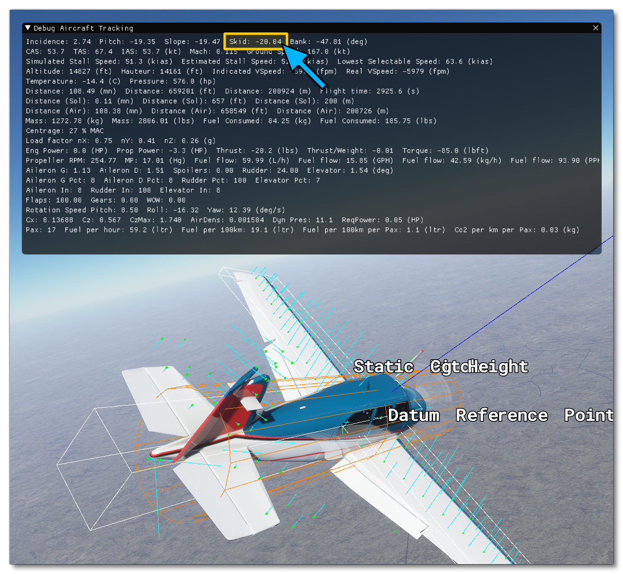
At this stage, you should perform an approach test:
- put the plane at low speed
- go full rudder
- check the skid angle of the airplane
Most planes are able to skid during a stable cross control by about 10° to 20°:
In order to adjust the rudder authority, without changing the rudder surface or maximum deflection angle, which should be based on real data, two parameters are available in the FLIGHT TUNING panel of the Aircraft Editor, the Rudder Effectiveness and the Rudder Max Angular Scalar. In the flight_model.cfg file these are under the [FLIGHT_TUNING] header:
rudder_effectiveness = 1 ; Scales the vertical tail area
rudder_maxangle_scalar = 0.75 ; Scales the rudder deflection maximum angle
Also, you may want to go back to adjusting your aileron authority at this stage as most aircraft will have enough aileron control to counter a full rudder deflection and maintain a stable cross controlled flight.
Now it is time to set the aircraft yaw stability. Based on the dimensions and geometric definition of the aircraft, our surface based aerodynamics simulation automatically calculates the minimum rotational air friction. But because a real airplane is not made of perfect surfaces with a perfect shape, real rotational friction is always going to be higher. You can adjust the rotational friction using the Yaw Stability setting in the FLIGHT TUNING panel of the Aircraft Editor, or under the [FLIGHT_TUNING] section in the flight_model.cfg:
yaw_stability = 0.1
You need to enter a value that is higher than zero, for backwards compatibility with the legacy flight model. You can enter 0.01 if you want only the minimum rotational friction, and if the plane has too much yaw inertia, you can enter higher values.
Elevator
Before starting the elevator adjustments, it is very important that you correctly completed the weight and balance adjustments, as explained further up this page. It may be a good idea at this stage to go over the again and check the parameters before moving on.
You can define the Elevator Area (sqft) if it's not already been done from the GEOMETRY panel. This has the following setting in the flight_model.cfg file, under the [AIRPLANE_GEOMETRY] header:
elevator_area = 17.4 ; Elevator area (SQUARE FEET)
If you have this exact data, use it. If you don't have this data, you can set a value that is in the same order of magnitude as the rudder or aileron surface areas.
On this panel you can also go ahead and define the angle limits of the elevator using the Elevator Up Limit and Elevator Down Limit settings. These can also be set in the [AIRPLANE_GEOMETRY] section of the flight_model.cfg file:
elevator_up_limit = 28 ; Elevator max deflection up angle (DEGREES)
elevator_down_limit = 23 ; Elevator max deflection down angle (absolute value) (DEGREES)
If you have this data, use it. If not, it can usually be found on the FAA website. In general elevator limits are between 20º and 30°. The up limit angle needs to be important enough to allow flaring the aircraft upon landing.
This is a table that defines the ratio of elevator control depending on the amount of dynamic air pressure, and can be set by scrolling to the bottom of the GEOMETRY panel to the section on Elasticity Tables and selecting the Elevator tab. If you are editing the flight_model.cfg file, you'd use something like the following:
elevator_elasticity_table = 0:1, 25:1, 50:0.75, 75:0.5, 100:0.33
At this stage, you should perform a stall test:
- Put the plane at lower speed
- power off
- try to fly steady without descending
You will need to increase your elevator position closer and closer to the upper limit. When the wing stalls, you will see the lift force vectors on the surfaces change color. Yellow is getting close to stall, red is stalling, blue is a fully stalled surface:
Stalling is computed individually for each surface in the new aerodynamics model of Microsoft Flight Simulator. Most aircraft will allow getting very close to the stall speed limit when the elevator is maintained at the maximum upwards deflection. Some planes will never drop and start descending and others will have a sharp drop. Increasing or decreasing the maximum deflection angle of the elevator, or increasing or decreasing the effect of the elevator deflection, can allow you to achieve a higher or lower maximum angle of attack and therefore change the type of stall of the aircraft.
In order to adjust the elevator authority, without changing the elevator surface or maximum deflection angle - which should be based on real data - two parameters are available in the FLIGHT TUNING panel of the Aircraft Editor, the Elevator Effectiveness and the Elevator Max Angular Scalar. In the flight_model.cfg file these are under the [FLIGHT_TUNING] header:
elevator_effectiveness = 1 ; Scales the horizontal tail area
elevator_maxangle_scalar = 1 ; Scales the elevator deflection maximum angle
Now it is time to set the aircraft pitch stability. Based on the dimensions and geometric definition of the aircraft, our surface based aerodynamics simulation automatically calculates the minimum rotational air friction. But because a real airplane is not made of perfect surfaces with a perfect shape, real rotational friction is always going to be higher. To help with this you can adjust the Pitch Stability value in the Aircraft Editor, or adjust the value manually in the flight_model.cfg file under the [FLIGHT_TUNING] section:
pitch_stability = 0.1
You need to enter a value that is higher than zero, for backwards compatibility with the legacy flight model. You can enter 0.01 if you want only the minimum rotational friction, and if the plane has too much pitch inertia, you can enter higher values.
Flaps and spoilers
To define flaps and spoilers, there is both an aerodynamic and a geometrical definition. The geometrical definition will be used to change the the various physical properties of the spoiler or flap, and the aerodynamic definition will be fed into the lift and drag polar curves that will be used to perform the virtual wind tunnel normalization of the aircraft's surfaces.
Spoilers
NOTE: If the aircraft does not have spoilers, you can leave all parameters in this section set to 0.
Spoiler geometry is defined in the GEOMETRY panel of the Aircraft Editor, under the Controls / Properties section. If the aircraft has spoilers then you should input the available data to fill out the available settings. In the flight_model.cfg file, these would be under the [AIRPLANE_GEOMETRY] header:
spoiler_limit = 0
spoilerons_available = 0
aileron_to_spoileron_gain = 0
min_ailerons_for_spoilerons = 0
min_flaps_for_spoilerons = 0
spoiler_extension_time = 0
spoiler_handle_available = 0
auto_spoiler_available = 0
You can define the lift and drag coefficients that will be added when the spoilers are fully deployed from the AERODYNAMICS panel, on the Lift and Drag tabs, respectively. These are set under the header in the flight_model.cfg file:
lift_coef_spoilers = 0 ; Change in lift due to spoilers
drag_coef_spoilers = 0 ; Change to drag due to spoilers
Based on the coefficients you enter here, an equation will be solved to compute the required deflection of the surfaces in the underlying surface based aerodynamics model. Then, the plane with the resulting spoiler deflection will be run 100 times through the virtual wind tunnel and the exact deflection will be readjusted to achieve the exact lift coefficient change desired. Advanced effects such as pitch moment generated by spoilers will be automatically simulated based on the actual surface aerodynamics simulation and cannot be adjusted.
Flaps
NOTE: If the aircraft does not have flaps, you can leave all parameters in this section set to 0.
If the aircraft has flaps you can define the lift and drag coefficients that will be added when the flaps are fully deployed from the AERODYNAMICS panel, on the Lift and Drag tabs, respectively. These are set under the header in the flight_model.cfg file:
lift_coef_flaps = 0.3379 ; Change in lift due to flaps
drag_coef_flaps = 0.047
At this stage, the lift and drag bonuses of flaps can only be defined globally. In the legacy simulation, they were entirely added to the resulting lift and drag of the simulation. In the new simulation - as they are used for the surface deflection and wind tunnel normalization - the addition of the lift coefficient cannot be achieved as it is not physically correct at all angles of attack. Our surface deflection and wind-tunnel normalization guarantees that the total lift and drag added will correspond to the indicated values at the stall angle of attack. At an angle of attack of zero, the resulting increase of lift and drag is usually about half as much and at negative angles of attack, the effect tends to wash out completely. This is a large change compared to the legacy simulation which would have very large and incorrect lift coefficient at negative angles of attack.
Now lets define the geometrical data of the flaps. In the Aircraft Editor, these are defined from from the FLAPS panel:
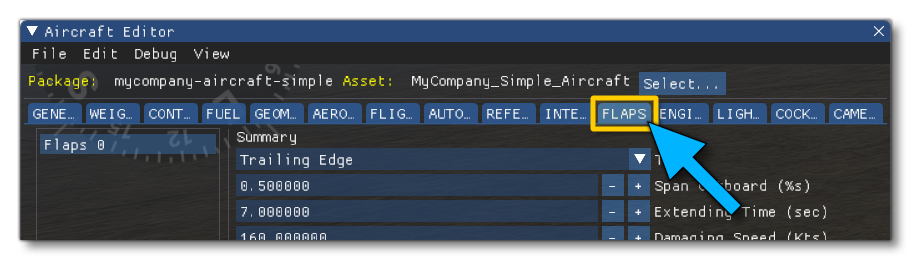
Here you can add as many flaps as required, and edit any existing flaps. Most planes will require only one flap system, but the possibility to add more if required is there and you can add flaps by clicking the + at the bottom of the window, and remove them by clicking the X button (after selecting a flap from the list).
To start with we need to define the ratio of wing span corresponding to how much the flaps will reach out on the wing, which is done by changing the Span Outboard (%s) value, or by editing the following value in the flight_model.CFG, under the [FLAPS.N] header (where N is the flaps index, starting at 0):
span-outboard = 0.45 ; Outboard span area (added area) (percentage, non dimensional)
Now, because the lift and drag parameters of the flaps are multiplied by the deflection angle in radians, we need a scalar that multiplies the effect of the flaps lift and drag in order to achieve the above required values. These values are usually between 1.2 and 1.5, and can be set using the Lift Scaler and Drag Scalar parameters in the Aircraft Editor, or the following parameters in the flight_model.cfg (again, under the [FLAPS. N] header):
lift_scalar = 1.3 ; Scalar coefficient to ponderate global flap lift coef (non dimensioned)
drag_scalar = 1.3 ; Scalar coefficient to ponderate global flap drag coef (non dimensioned)
Advanced effects such as the resulting pitch effect of flaps deployment are automatically simulated based on the actual aerodynamics surface deflection and cannot be controlled at this stage.
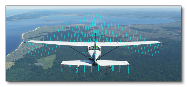
Now that flaps and spoilers are defined, it is time to test an approach. You should see the increased lift forces being applied to the wing match the part of the wing where the flaps are located:
Advanced wing effects
Now the plane should fly correctly and achieve its core performance values, so it's time to change some of the new, advanced fields that can be defined to adjust the shape of the aircraft further and obtain specific effects.
Wing Camber
The Wing Camber parameter tells the system how the airflow will affect the lift forces as it moves over the wing. When the airflow is moving over the wing, it is bent. The air particles are first accelerating upwards a little and then they accelerate downwards a lot. The resulting reaction creates lift on the wing. When air particles accelerate downwards, the wing accelerates upwards which corresponds to our lift force. This uneven acceleration of air particles, up first and then down, creates a moment on the surface. The larger the difference, the more it wants to pitch down. The effect is fully automatic but this wing camber parameter allows you to define how much of the effect you want to get. Basically, the more the wing is cambered, the larger the difference between the up and then down acceleration of air, and the larger the pitch moment.
You can define the wing camber setting in the GEOMETRY panel of the Aircraft Editor - in the Wing section - or under the [AIRPLANE_GEOMETRY] header of the flight_model.cfg:
wing_camber = 1 ; (DEGREES)
NOTE: Wing camber cannot be zero or negative. It has to be a positive value for our aerodynamics model to work. If you set it to 0, it will default back to 1. A wing camber of 1 degree produces good results in most cases. If there is too much pitch moment on the wing, you can reduce the wing camber.
Wing Twist
The Wing Twist parameter (also called wing washout) affects the incidence angle of the surfaces. On most planes the incidence at the exterior edge of the wing is lower than the incidence close to the fuselage. Because wings stall at a given angle of attack, this allows the stall to occur in the middle of the wing first and then to propagate towards the end of the wing. While this happens, and because the end is not stalled yet, the ailerons remain effective allowing roll control over the aircraft. This effect is an important component of whether the aircraft will enter a spin when it stalls.
You can define the wing twist setting in the GEOMETRY panel of the Aircraft Editor - in the Wing section - or under the [AIRPLANE_GEOMETRY] header of the flight_model.cfg:
wing_twist = -3 ; Wing twist epsilon (DEGREES)
Wing twist will also result in the wing producing negative lift at the outside and positive lift close to the fuselage when flying at high speeds.
Wing Incidence
Most aircraft have some wing incidence to produce some quantity of lift when the aircraft pitch/AoA is zero. You can define this value in the GEOMETRY panel of the Aircraft Editor - in the Wing section - or under the [AIRPLANE_GEOMETRY] header of the flight_model.cfg:
wing_incidence = 1.5 ; Wing incidence (DEGREES)
As our aircraft will get normalized through the virtual wind tunnel, the overall lift and drag curves will correspond to the data defined for the base aerodynamic parameters (explained further up this page). But setting the correct wing incidence will affect each surface and will have an effect on the exact level of lift and drag, depending on the pitch of the aircraft. Just like the definition of wing twist, it will slightly change the shape of the lift and drag curves, without changing the lift and drag values at maximum and zero AoA.
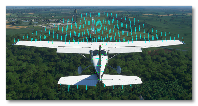
Advanced Engine Effects
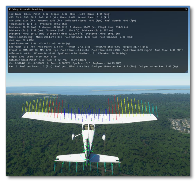
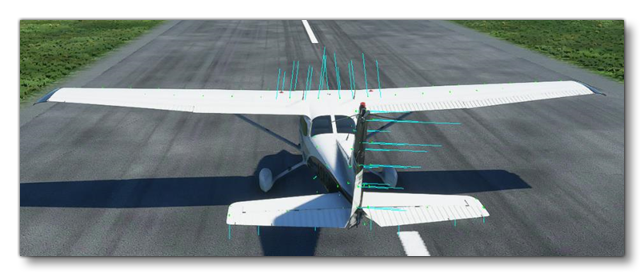
Just like the effects of atmospheric turbulence, basic engine effects caused by the airflow generated by the engine - such as the increased effect of rudder and elevator, the increased lift of the wings, or turbulence's generated by the propeller - are automatically simulated by the new surface based aerodynamics simulation. When doing the engine tests before takeoff, you will feel the aircraft getting shaken by the prop wash. You will feel the additional authority of the control surfaces the propwash generates as well as the additional lift. This is illustrated in the image below:
But some, mostly unwanted, effects are also created by the engine and propellers and can be simulated. These effect can be easily defined by following a few simple steps. It is important to understand that engine effects compensate each other and that you cannot only enable one of them or you will get parasitic and annoying roll or yaw movements.
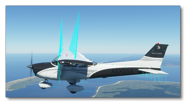
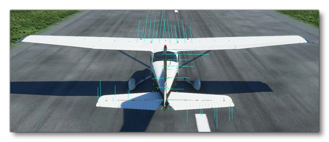
Propeller Wash Vortex
The most important effect is caused by the propeller wash that isn't flowing in a straight line backwards but making circles around the aircraft in the form of a vortex. Because of that, it will hit the left horizontal tail, the vertical tail and the right horizontal tail differently, creating a roll and yaw movement:
 NOTE: In order to see these effects in the debug visualisation, make sure the auto rudder/take off rudder assistance is disabled in the piloting assistance options menu.
In order to compensate for the induced yaw moment at cruise speed, we will automatically add a 0.45° deflection of the rudder. In order to enable this effect and set it's strength you can either edit the value in the Aircraft Editor from the FLIGHT TUNING panel, or edit the following parameter in the [FLIGHT_TUNING] section of the flight_model.cfg file:
engine_wash_on_roll = 1 ; Scale the circular vortex of the engine wash up or down
We recommend setting this effect to 1 which represents the simulation that is closest to reality.
The automatic 0.45° deflection of the rudder won't be enough to counter the prop wash effect however, and the definition of one other engine effect will be necessary. By making the propeller turn, there is a rotational friction that is caused that makes the plane roll in the opposite direction, called the "torque on roll" effect. This can also be edited in the Aircraft Editor under the FLIGHT TUNING panel using the Engine Wash On Roll setting, or by editing the following parameter in the [FLIGHT_TUNING] section of the flight_model.cfg file:
torque_on_roll = 1.75
We recommend setting the torque on roll effect to 1 first and then to adjust it slightly so that the aircraft does not roll or yaw sideways at cruise speed with cruise power.
Now, there are 2 other engine effects which are available and that are encountered mostly during rotation at slow speeds, or maneuvers, or when the engine power is changed rapidly. These are also in the Aircraft Editor under the FLIGHT TUNING panel:
- P Factor On Yaw
- Gyro Precession On Yaw
These can also be edited in the flight_model.cfg file, under the [FLIGHT_TUNING] header:
p_factor_on_yaw = 1
gyro_precession_on_yaw = 1
we recommend setting them to 1 as they are realistically calculated when applied a scale of one.