ELECTRICAL SYSTEMS
The electrical system for an aircraft is similar to the modern fuel system, since it is comprised of various different components that are connected - and interact - with each other. Setting up the electrical systems is essential for the correct functioning of the aircraft, and it's also required for the modern fuel system which why we'll be setting this up first. Each of the components is listed on the following page of the documentation:
The electrical system allows you to describe which circuits are present in the aircraft and which buses they are connected to (which will then control when those circuits have power or not). Which circuits are actually present will also control what the plane can do, so if your plane has two distinct landing lights, you will want to define two different landing light circuits in order to be able to control their state individually.
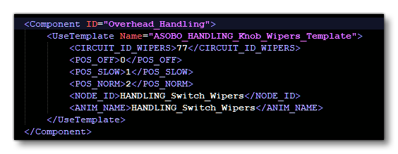
It also worth mentioning that some of the templates in the Model Behaviors are designed to use a predefined circuit ID which can be used to either control the state of the circuit, or only display an emissive texture when this circuit is powered. This system is frequently used to control the brightness of glasscockpits, for example:

In the above example, if the circuit is OFF, the wipers will not move. Circuits are identified by a given ID, so it is better to create all the IDs ahead of time within the model behavior XML rather than creating them as you go, as this reduces the chances that you may need to modify multiple IDs later, which could happen if you have to remove a circuit.
IMPORTANT! When using the electrical system, please ensure that the Name property for each element that has it is unique, as it is used to identify their connections.
Buses
When it actually comes time to adding the electrical system into the systems.cfg file, the first step is to create the buses on which all the circuits will be connected. Having a bus dedicated to a number of systems is a good way to ensure that those systems can all be disconnected at once with an interaction. The example below shows the creation of the electrical system buses:
bus.1 = Name:AC_BUS_1
bus.2 = Connections:bus.1#Name:AC_ESS_BUS
bus.3 = Name:AC_BUS_2
bus.4 = Connections:bus.1#Name:DC_BUS_1
bus.5 = Connections:bus.3#Name:DC_BUS_2
bus.6 = Connections:bus.4, bus.5#Name:DC_BAT_BUS
bus.7 = Connections:bus.4#Name:DC_ESS_BUS
bus.8 = Connections:bus.1, bus.3#Name:AC_CROSS_BUS
bus.9 = Connections:bus.10, bus.11#Name:HOT_BAT_BUS
bus.10 = Connections:bus.6#Name:MAIN_BAT_BUS
bus.11 = Connections:bus.6#Name:ALT_BAT_BUS

Power Supply
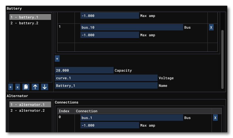
Next, at least one power supplier (either from batteries, alternators, or external power sources) should be added, along with some parameters to ensure it provides the right amount of power. These power supplies are then connected to buses and will provide power to those buses:
battery.1 = Connections:bus.9,bus.10#Capacity:28#Voltage:curve.1#Name:Battery_1 ; Battery_1
battery.2 = Connections:bus.9,bus.11#Capacity:28#Voltage:curve.1#Name:Battery_2 ; Battery_2
alternator.1 = Connections:bus.1#iEng:0#RatedVoltage:28.5#Load:curve.2
alternator.2 = Connections:bus.3#iEng:1#RatedVoltage:28.5#Load:curve.2
alternator.3 = Connections:bus.8#IsOnAPU:True#RatedVoltage:28.5#Load:curve.2#Voltage:curve.3
externalpower.1 = Connections:bus.8#RatedVoltage:28.5#Load:400

Curves
You may also need to setup one or more curves that will be used in the power supply to control the Load and Voltage of those supplies. Curves are simple tables, defined something like this:
curve.1 = 0:21, 0.1:22.5, 0.5:24, 0.9:25, 1:25.4 ; Battery voltage for capacity %
curve.2 = 0.05:0, 0.25:60, .35:80, 0.9:90 ; Load from RPM table 30A at idle speed & 60 at 90%rpm
curve.3 = 0:25.4, 1:28.5 ; APU voltage for RPM %

Circuits
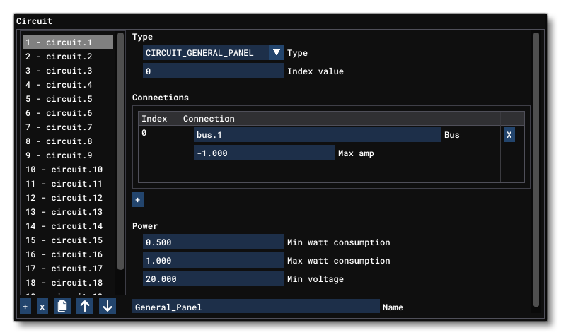
Finally, you can create your circuits to connect to the buses. These circuit types will control how the circuit will affect the associated features within the aircraft, whether that's lights, fuel pumps, landing gear, etc... The extensive example below shows various types of circuits and how they're set up:
circuit.1 = Type:CIRCUIT_GENERAL_PANEL#Connections:bus.2#Power:0.5,1,20.0#Name:General_Panel ; General panel
circuit.2 = Type:CIRCUIT_FUEL_PUMP:1#Connections:bus.2#Power:3, 5, 20.0#Name:Fuel_Pump_Center1 ; Fuel Pump 5W
circuit.3 = Type:CIRCUIT_FUEL_PUMP:2#Connections:bus.2#Power:3, 5, 20.0#Name:Fuel_Pump_Center2 ; Fuel Pump 5W
circuit.4 = Type:CIRCUIT_STANDBY_VACUUM#Connections:bus.2#Power:5,10,20.0#Name:STBY_Vacuum ; stby vacuum
circuit.5 = Type:CIRCUIT_GEAR_MOTOR#Connections:bus.2#Power:200, 240, 20.0#Name:Gear_Motor ; Gear motor
circuit.6 = Type:CIRCUIT_GEAR_WARNING#Connections:bus.2#Power:2.5, 5, 17.0#Name:Gear_Warning ; Gear warning
circuit.7 = Type:CIRCUIT_PITOT_HEAT#Connections:bus.2#Power:30, 40, 20.0#Name:Pitot_Heat ; pitot_heat 40W
circuit.8 = Type:CIRCUIT_STARTER:1#Connections:bus.2#Power:20, 35, 20.0#Name:Starter_1 ; Bleed Air Starter 35W
circuit.9 = Type:CIRCUIT_STARTER:2#Connections:bus.2#Power:20, 35, 20.0#Name:Starter_2 ; Bleed Air Starter 35W
circuit.10 = Type:CIRCUIT_APU_STARTER:1#Connections:bus.2#Power:2000, 3500, 20.0#Name:Starter_APU ; APU Starter 1500W
circuit.11 = Type:CIRCUIT_LIGHT_NAV:1#Connections:bus.2#Power:10, 15, 20.0#Name:Nav_Light_1 ; nav 1 light 15W
circuit.12 = Type:CIRCUIT_LIGHT_NAV:2#Connections:bus.2#Power:10, 15, 20.0#Name:Nav_Light_2 ; nav 2 light 15W
circuit.13 = Type:CIRCUIT_LIGHT_NAV:3#Connections:bus.2#Power:10, 15, 20.0#Name:Nav_Light_3 ; nav 3 light 15W
circuit.14 = Type:CIRCUIT_LIGHT_NAV:4#Connections:bus.2#Power:10, 15, 20.0#Name:Nav_Light_3 ; nav 4 light 15W
circuit.15 = Type:CIRCUIT_LIGHT_BEACON:1#Connections:bus.2#Power:6, 8, 20.0#Name:Beacon_Light ; Beacon light 28V @ 0.26A
circuit.16 = Type:CIRCUIT_LIGHT_BEACON:2#Connections:bus.2#Power:6, 8, 20.0#Name:Beacon_Light ; Beacon light 28V @ 0.26A
circuit.17 = Type:CIRCUIT_LIGHT_LANDING:1#Connections:bus.2#Power:80, 95, 20.0#Name:Landing_Light_Takeoff ; Landing light 95W
circuit.18 = Type:CIRCUIT_LIGHT_LANDING:2#Connections:bus.2#Power:80, 95, 20.0#Name:Landing_Light ; Landing light 95W
circuit.19 = Type:CIRCUIT_LIGHT_LANDING:3#Connections:bus.2#Power:80, 95, 20.0#Name:Landing_Light ; Landing light 95W
.
.
.
circuit.49 = Type:CIRCUIT_XML:1#Connections:bus.2#Power:2.5, 5, 17.0#Name:XML_Warnings ; Warnings
circuit.50 = Type:CIRCUIT_XML:2#Connections:bus.2#Power:0, 0, 0.0#Name:XML_Alt_Field ; Alt field breaker
circuit.51 = Type:CIRCUIT_XML:3#Connections:bus.2#Power:1, 2, 17.0#Name:XML_STBY_Indicator_Light ; STBY Indicator light
circuit.52 = Type:CIRCUIT_PFD#Connections:bus.2#Power:30, 40, 20.0#Name:PFD ; PFD 40W
circuit.53 = Type:CIRCUIT_MFD#Connections:bus.2#Power:25, 30, 20.0#Name:MFD ; MFD 30W
circuit.54 = Type:CIRCUIT_XML:4#Connections:bus.2#Power:25, 30, 20.0#Name:EICAS1
circuit.55 = Type:CIRCUIT_XML:5#Connections:bus.2#Power:25, 30, 20.0#Name:EICAS2
circuit.56 = Type:CIRCUIT_XML:6#Connections:bus.2#Power:25, 30, 20.0#Name:CDU
circuit.57 = Type:CIRCUIT_XML:7#Connections:bus.2#Power:25, 30, 20.0#Name:FCU
circuit.58 = Type:CIRCUIT_LIGHT_GLARESHIELD:1#Connections:bus.2#Power:3, 5, 20.0#Name:Glareshield_1_Light ; Glareshield 1 light 5W
circuit.59 = Type:CIRCUIT_LIGHT_GLARESHIELD:2#Connections:bus.2#Power:3, 5, 20.0#Name:Glareshield_2_Light ; Glareshield 2 light 5W
circuit.60 = Type:CIRCUIT_LIGHT_GLARESHIELD:3#Connections:bus.2#Power:3, 5, 20.0#Name:Glareshield_3_Light ; Glareshield 3 light 5W
circuit.61 = Type:CIRCUIT_LIGHT_PANEL:2#Connections:bus.2#Power:2, 5, 20.0#Name:Panel_Light_2 ; panel light 5W
circuit.62 = Type:CIRCUIT_LIGHT_PANEL:3#Connections:bus.2#Power:2, 5, 20.0#Name:Panel_Light_3 ; panel light 5W
circuit.63 = Type:CIRCUIT_LIGHT_PANEL:4#Connections:bus.2#Power:2, 5, 20.0#Name:Panel_Light_Overhead ; panel light overhead 5W
circuit.64 = Type:CIRCUIT_FUEL_PUMP:3#Connections:bus.2#Power:3, 5, 20.0#Name:Fuel_Pump_Left1 ; Fuel Pump 5W
circuit.65 = Type:CIRCUIT_FUEL_PUMP:4#Connections:bus.2#Power:3, 5, 20.0#Name:Fuel_Pump_Right1 ; Fuel Pump 5W
circuit.66 = Type:CIRCUIT_FUEL_PUMP:5#Connections:bus.2#Power:3, 5, 20.0#Name:Fuel_Pump_Left2 ; Fuel Pump 5W
circuit.67 = Type:CIRCUIT_FUEL_PUMP:6#Connections:bus.2#Power:3, 5, 20.0#Name:Fuel_Pump_Right2 ; Fuel Pump 5W
circuit.68 = Type:CIRCUIT_FUEL_VALVE:1#Connections:bus.2#Power:3, 5, 20.0#Name:Fuel_Valve_CrossFeed ; Fuel Valves 5W
circuit.69 = Type:CIRCUIT_FUEL_VALVE:2#Connections:bus.2#Power:3, 5, 20.0#Name:Fuel_Valve_LXFer_1 ; Fuel Valves 5W
circuit.70 = Type:CIRCUIT_FUEL_VALVE:3#Connections:bus.2#Power:3, 5, 20.0#Name:Fuel_Valve_RXFer_1 ; Fuel Valves 5W
circuit.71 = Type:CIRCUIT_FUEL_VALVE:4#Connections:bus.2#Power:3, 5, 20.0#Name:Fuel_Valve_LXFer_2 ; Fuel Valves 5W
circuit.72 = Type:CIRCUIT_FUEL_VALVE:5#Connections:bus.2#Power:3, 5, 20.0#Name:Fuel_Valve_RXFer_2 ; Fuel Valves 5W
circuit.73 = Type:CIRCUIT_FUEL_VALVE:6#Connections:bus.2#Power:3, 5, 20.0#Name:Fuel_Valve_LEngine ; Fuel Valves 5W
circuit.74 = Type:CIRCUIT_FUEL_VALVE:7#Connections:bus.2#Power:3, 5, 20.0#Name:Fuel_Valve_REngine ; Fuel Valves 5W
circuit.75 = Type:CIRCUIT_FUEL_VALVE:8#Connections:bus.2#Power:3, 5, 20.0#Name:Fuel_Valve_APU ; Fuel Valves 5W
circuit.76 = Type:CIRCUIT_XML:8#Connections:bus.9#Power:3, 5, 20.0#Name:HotBatteryCircuit ; Hot Battery Circuit 5W
circuit.77 = Type:CIRCUIT_XML:9#Connections:bus.2#Power:3, 5, 20.0#Name:Wipers ; Wipers 5W
.
.
etc...
Debugging The Electrical System
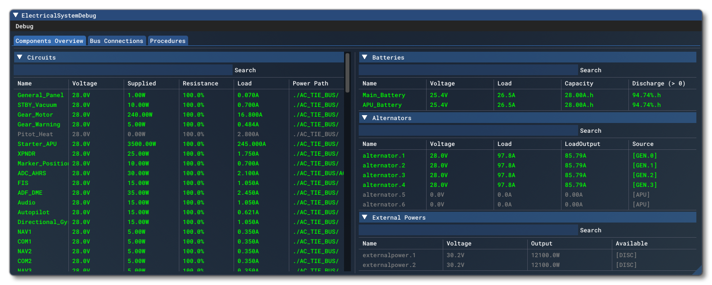
The Model Behaviors debug window has a sub window for Electrical Systems, which is enabled by checking the Show Electrical System Debug option in the Systems tab:

The first step when using this debug window is to check the state of the electrical circuits, and in particular any that you are interested in or think there is a problem with. You can find a list of all the circuits from the left side of the Component Overview tab of the debug window. The circuits are color coded to allow you to quickly see where the issues are:
- Green circuits are powered
- Gray circuits are shut down
- Red circuits are enabled but are not receiving sufficient power/voltage to function.
In general, a red circuit should be investigated.
A frequent issue to be aware of when working with the electrical system is that having too many circuits will use too much power compared to the power being generated by the available power supplies (especially at low RPM). This can cause some circuits to turn red and stop functioning. There are a few ways to correct this:
- Look through the list of circuits and check if they are all necessary, and that they are not using more power than they should.
- Look through the list of power supplies and ensure that they provide enough power to power the aircraft. Check while at idle RPM, and verify how much power the alternator will generate at that RPM and whether it is enough to power the systems that should be powered.
- Ensure that circuits which should only be enabled temporarily are not somehow stuck on enabled. As an example, if the starter is always enabled it takes a large amount of power to run and will empty out the battery quickly.
Another frequent issue is to have an offset between the indices of the circuits and the indices used in the XML/JS. This can generally be quickly spotted by toggling the circuit state via an interaction - for example, toggling a switch for a light - and checking which circuits gets affected in the debug window.