WHEELS AND CONTACT POINTS
This page details how to setup and configure the contact and friction models for your aircraft in Microsoft Flight Simulator. These values can all be set in the Aircraft Editor from the Contact Points section of the Flight Model tab:

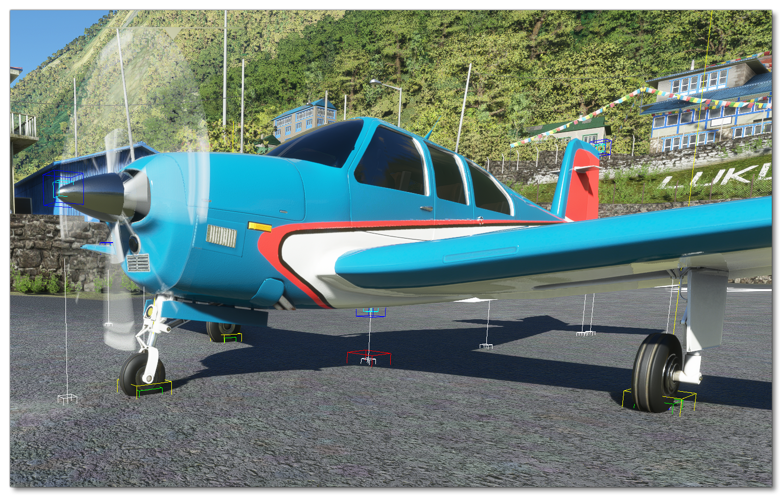
By default when you select this panel the sim should display the different contact points using a blue box and also show their projection to the nearest surface using a white line and a white box (the line represents the surface normal). Wheels will also be represented in this view as yellow boxes with an additional green box for the contact force:
NOTE: If you do not see this information when selecting the panel, or you wish to toggle it on or off, you can use the Aircraft Editor Debug menu and select/deselect Wheels.
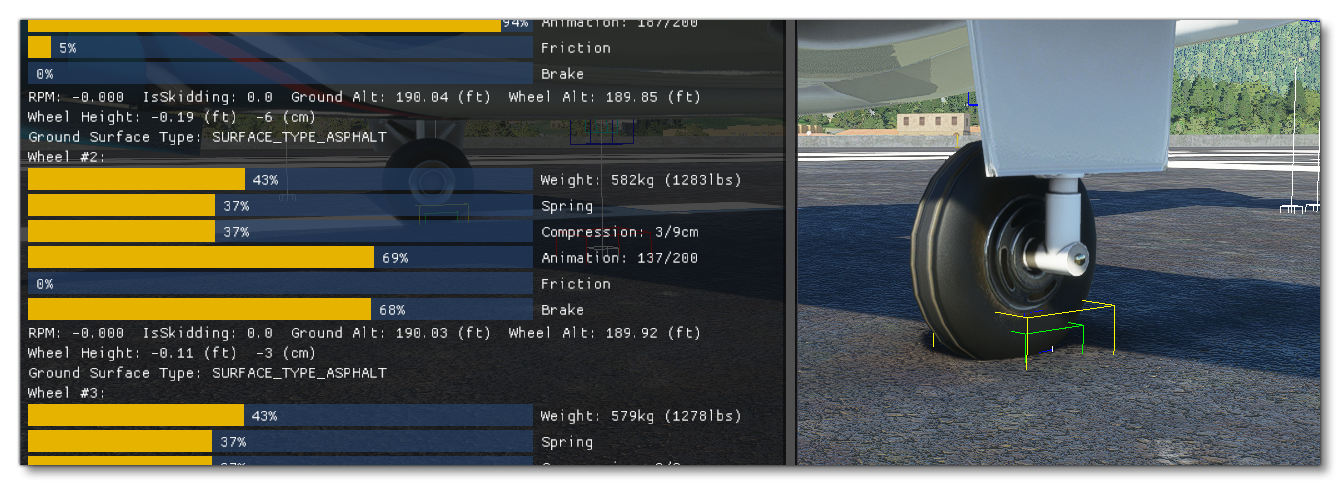
Selecting the Contact/Brakes panel in the Aircraft Editor will also open the following debug window which can be usedto help understand the results of the data set you'll be editing:

In the Aircraft Editor, on the left, you'll see all the defined contact points for the aircraft, and you can add or remove contact points using the + and - buttons at the bottom of the editor. With our new aircraft model, you'll need start by adding in the contact points one at a time, usually positioning a minimum of 8, as follows:

When adding contact points, you should set up the wheels first and for those you'll need to set up all - or most - of the following parameters:
- Type - Sets the type of contact point.
- Pos - The position of the contact point/wheel relative to the center point of the aircraft. Note that this is made a lot easier if you enable the Gizmo tool and then position the points visually.
- Crash velocity - The maximum velocity at which the wheel will work before being considered a crash.
- Brake - The brake type for the wheel.
- Wheel radius - The wheel radius.
- Wheel steering angle - The maximum angle the wheel can be turned when steering.
- Static compression - This sets the landing gear compression when the airplane is on the ground with all the weight compressing the gears.
- Max to static compression - This sets the maximum to static compression ratio. The higher this ratio is, the "stiffer" the suspension will be, but the higher the loads it can absorb before hitting maximum travel.
- Damping ratio - This represents a ratio of how much energy is lost upon impact.
- Extend time - The time required for the wheel to be extended from the aircraft.
- Retract time - The time required for the wheel to be retracted into the aircraft.
- Sound ID - The ID of the sound effect to use.
- Airspeed retr. - The airspeed at which the landing gear needs to be retracted.
- Airspeed. dam. - The airspeed at which the landing gear will be damaged if not retracted.
- Exponential Constant - This allows you to change the spring reaction curve.
These parameters are all set using a single entry in the [CONTACT_POINTS] section of the flight_model.cfg file, which follows this format:
point.number = class, long_pos, lat_pos, vert_pos, crash_velocity, braking_enum, wheel_radius, steer_angle, static_compression, max_to_static_compression_ratio, dapting_ratio, extend_time, retract_time, sound_enum, airpseed_limit, airspeed_damage, exponential_constant
Note that the contact between a wheel and the ground is a surface, but only a point is simulated. Therefor, in order to give the best stability to the plane, we recommend that the wheel points are positioned at the exterior limits of the wheel's triangle.

Another thing to note is that the compression parameters are displayed in the debug window, and you can use the visual feedback to adjust the compression ratios and distances so that the suspensions are compressed between 30% and 50% when standing on the runway. You want to ensure that the plane has the correct pitch when parked - a pitch that is too high or too low will negatively impact stability during take-off and landing.
A correctly positioned wheel contact point should look something like this:
You can then position the other contact (scrape) points so that they are aligned correctly with the aircraft model. These points are set similarly to the wheels but most of the fields can be set to zero.
Retractable Floats
If your aircraft model is set up with the animations for retractable floats, then there are a couple of import things that you should know in relation to getting them to work correctly within the simulation.
To start with, you must define a "wheel" contact point as well as the "float" contact points in order for the floats to be evaluated as part of the retract/extend process. This contact point can be placed in a position where it does not interfere with the operation of the aircraft.
Once you have the contact points set up, the animations themselves will be controlled using the following events and SimVars:
- Events:
RETRACT_FLOAT_SWITCH_INCandRETRACT_FLOAT_SWITCH_DEC - SimVars:
RETRACT FLOAT SWITCH,RETRACT LEFT FLOAT EXTENDED, andRETRACT RIGHT FLOAT EXTENDED