SURFACE DETAIL
This page outlines the best way to apply different types of surface detail to the aircraft airframe.
Normal Maps
Some aircraft have simple bodywork designs and require very little high-fidelity detail. These aircraft can have these small amounts of detail modelled, with little or no normal baking, and can still come in under the recommended triangle count. In general this is the most favourable way of dealing details. However, some other aircraft can have far more detail that needs to be represented in the model to be accurate and realistic, and this cannot possibly be done within the recommended triangle budget. Therefore these details needs to be baked down to a normal map.
As a general rule, if a detail area has a silhouette it should be represented with geometry to maintain that silhouette, however if it is inside a recess and does not add to the overall silhouette of the aircraft then this can be baked to a normal map. If animations are required in these recessed areas, then these elements will of course need to be modeled to do so.
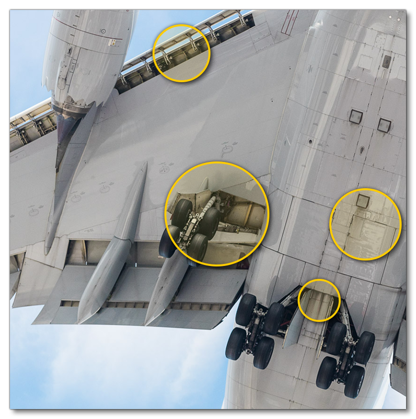
As an example, we'll look at an image of the interior mechanism of the landing gear housing - the different visible areas would be rendered as follows:
- the areas that are highlighted in orange are areas that will be required to be fully modeled, as they will need to be animated too.
- the areas that are highlighted in green are elements that are large, immobile, and/or close to the edges, and so these should be modelled with low resolution in order to support normal maps.
- all other areas can be textured purely with normal maps.

Rivets, Livery And Text
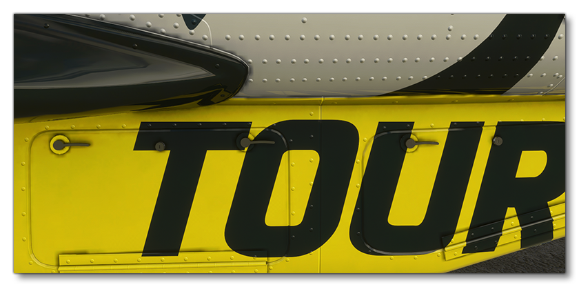
In order to add the multiple rivets and seams of the panels that make the airframe, as well as to add on the different text and warnings that are on the airframe, you need to use a decal mesh. These geometry based decals can also be used to create different liveries, and can help avoid using massive textures. For example the following image featuring a green livery was created by mapping UVs to a small green square in a small texture: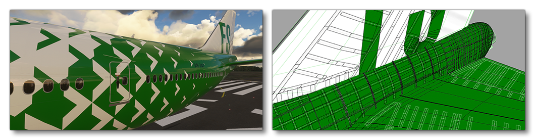
To create these decal effects you will need to use the Decal material. To set up this material you need to do the following:
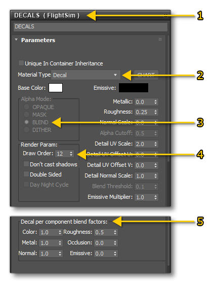
- Create a new FlightSim material
- Call it "DECAL" and set the Material Type to decal as well
- Set the Alpha Mode to BLEND.
- Set the Draw Order appropriately (see below for more details).
- Set the blend factors to achieve the look you require (see below for more details)
The only texture that is needed for this material is the albedo (Base Color) texture, however you can also supply Occlusion(R) Roughness(G) Metallic(B) and Normal textures if required.
Draw Order
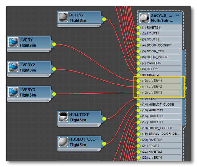
If several geometry decals with the same material are overlapping, the Microsoft Flight Simulator engine won't be able to know which one to show first and that will cause flickering in the simulation. To avoid that the material can be duplicated and put after the first one. For example, here you can see a livery material that has been duplicated 3 times:
The image below illustrates the way these materials would be layered onto the airframe to get the correct draw order without any flickering issues.
Blend Factors
The decal material has Decal Per Component Blend Factors, and these can be set to different values to achieve different effects. In all cases a value of 1 will completely show this parameter, and a value of 0 will show the material underneath it, with values in-between will be multiplied by the draw shader with the decals underneath. This is useful to achieve specific effects - for example with some rivet decals we can have 2 different materials depending on the expected result. We may want to have the rivets color painted like the rest of the airframe (especially when there is a livery) like in this image:
Or on the contrary we may want to have non painted rivets with the original steel material:
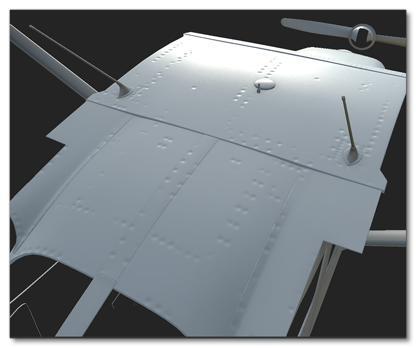
Bump Mapping Rivets
Once you have the rivets decal, you can use a program like Substance Painter to create the bumps and indentations that these rivets would have. For that you would start with rendering the rivets from the fuselage to a texture:
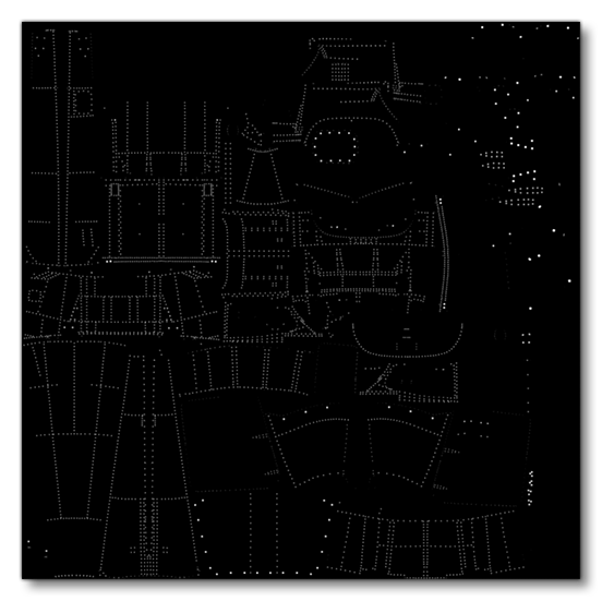
This texture will then be used in your program of choice (in the images below we show Substance Painter), to create the "dents" where the the rivets are. The general process would be to first apply the rivets texture in your program, like this: 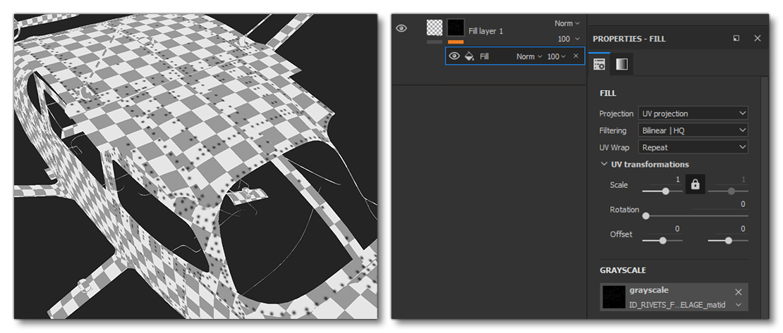
You would then blur the texture a little, and after that you will have a uniform bump effect under the rivets. However it's rather uniform, so you'd want to make it a little more random if you can. In Substance Painter this can be done easily by putting the layer in a folder, creating a mask on the folder, and then applying a cloud/random mask to it. By playing with the parameters of this mask you will be able to make the bump effect more or less visible.
Dirt And Grime
In order to achieve realistic dirt and grime on the aircraft without straying into caricature levels of wear and tear, we will want to use the roughness and normal textures to add life-style effects to the surfaces.
NOTE: This section talks about dirt on the airframe, but if you want to apply dirt to any of the glass elements, then please see the Dirt, Scratches and Fingerprints section on the Windshield And Windows page.
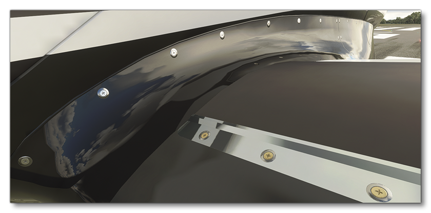
In the following image, for example, we can see how the panels are rippled - which is emphasized by the glossy paint - and the under panel detail is rougher with strong Ambient Occlusion and cavity grime. Also note how the dirt that is emitted from the landing gear shut lines is not thick and mud-like, but more of a fine blended oily grime, and depending on the references and what we want as a result, we may have more or less dirt.
But even for clean airplanes you should add some dirt, like on - and close to - the engine exhaust. It's thanks to these details that the aircraft will look a lot more realistic:
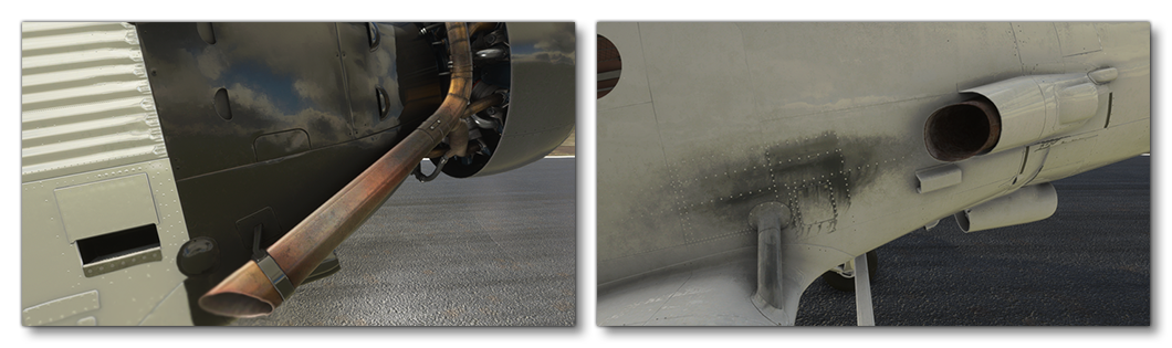
The best approach to achieve realistic results is to work with a lot of Visual References to see how the age and the weather can affect an airframe.