VR HELPERS
Before explaining how to make a cockpit work correctly in VR, it's important to understand the basics of how mouse/cockpit interactions are calculated when in VR, since in VR there no overlay UI and the mouse must obviously be rendered in a 3D space as it has to collide with the 3D environment without any depth issues. What this means is that in VR the mouse is a 3D asset that generally speaking has to collide with the first physical object "in front" of the user. For this to work correctly, we must first determine the general direction of the VR mouse, ie: the angle between the "front" of the user and the "user to VR mouse" vector. The direction is calculated from the general direction of the last rendered frame and the delta position of the system mouse compared to the last rendered frame, and the initial direction of the mouse - that is to say right after switching to VR - is the "front" of the user. Once we have that, a raycast is launched to determine the object the mouse is supposed to collide with in this general direction, and so we can determine the distance to the user on the "user to VR mouse" vector.
The Importance Of Collision Meshes
As mentioned previously, the mouse is placed along a segment that goes from the "front" of the head of the user to a certain direction and we need the collision meshes to determine where on this segment the mouse will be placed. In a 3D world - and so in VR - you cannot focus on two different depth planes simultaneously. You can test this yourself - if you focus your sight on an object near you, everything far away will look blurred and doubled, and vice-versa. In the VR world you can see this in the following screenshot, which is a representation of what appears in your headset (the left screen is the image given to your left eye and the right screen for your right eye):
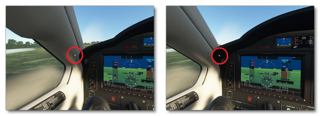
It may seem like there are two different mouse cursors since they do not appear at the same position on the cockpit. In fact there is only one mouse but it is not on the same visual plane as the cockpit. Thus if you try to focus the mouse, you will have difficulties seeing the cockpit, and if you focus on the cockpit you will have difficulties seeing the mouse. To avoid these issues the mouse must be "on" the cockpit and the current way it is done is by colliding with it along the segment of the mouse. To do so we try to find the intersection point between this segment and the collision mesh of the cockpit. So if there are no collision meshes, this issue will constantly be here.
You can find information on creating a correct collision mesh from the following section:
Collision Priority Based On The Depth Of The 3D Mouse
Here is the list of all the different elements the 3D mouse can collide with, in order of raycast priority:
- UI Collisions: when several UI elements are in collision with the VR mouse, the UI element that is the shortest distance from the user is prioritised other the others.
- Instruments: The orientation of the mouse when it collides with an instrument will depend on the orientation of the collision that is behind the instrument. This has been done to avoid having orientation jumps when colliding with tiny buttons, but note that it may lead to strange mouse orientations. However, the depth is always set based on the collision point, not the orientation.
- Collision Mesh. See the Collision Meshes section above for more details.
NOTE: if no collision is detected, the depth of the mouse is considered as one meter away from the "front" of the user.
Yoke/Stick Controls With Hand Gestures
In order to be able to control the yoke/stick with hand gestures in VR, you need to modify a few things in your aircraft which we'll outline here. Note that without these modifications, users can still control the yoke/stick, using the left joystick of the VR controllers, but it's recommended to implement "proper" VR controls when possible.
For information on general yoke/stick animations please see here:
VR Helpers
Within the aircraft cockpit model you will have to create 1 or 2 helpers as markers for the placement of the controllers, and another locator for the rotational axis. You should do this for each yoke or stick in the cockpit, following the guideline listed below:
- The helper for the hand must be a child of the yoke/stick, to move with the yoke/stick.
- For a stick, you would need to place the first helper where a pilot would usually put their hand. The second helper should be positioned at the center of rotation of the stick, which is most often at the base of the stick.
- For a yoke, you would need to place one helper on each side of the yoke, where the pilot would usually put their hands. The third helper should be placed at the center of rotation of the yoke.
- For a yoke on a stick, you would need to place one helper on each side of the yoke, where the pilot would usually put their hands. A third helper should be placed at the center of rotation of the yoke, and a fourth helper should be positioned at the center of rotation of the stick (which is often at the base of the stick).
NOTE: Take into account that you may be able to re-use any helper nodes that are already used to animate the stick in order to limit the node count, in particular at the base of the yoke/stick.
Naming
Below we list the recommended naming conventions to use for the nodes:
- Hand Locator Yoke (Joystick):
HANDLING_Yoke_1_Hand(One helper for two hands)
- Rotation Locator Yoke (Joystick):
HANDLING_Yoke_1_AxesHANDLING_Yoke_2_Axes(if there is a second point of rotation on the stick)
- Hand Locator Steering Wheel:
HANDLING_Yoke_1_Hand_Left(One helper for left hand)HANDLING_Yoke_1_Hand_Right(One helper for right hand)HANDLING_Yoke_1_Wheel_Center
- Hand Locator Steering Wheel On A Stick:
HANDLING_Yoke_1_Hand_Left(One helper for left hand)HANDLING_Yoke_1_Hand_Right(One helper for right hand)
- Rotation Locator Steering Wheel On A Stick:
HANDLING_Yoke_1_AxesHANDLING_Yoke_2_Axes
Collision Mesh For The Yoke
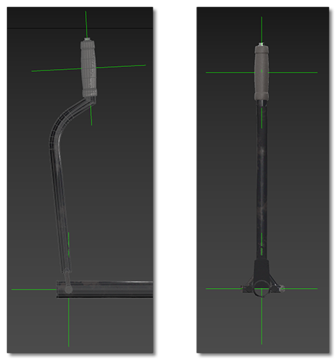
By default for the a yoke, collisions are detected using the bounding box of the yoke node (described by the yoke_node parameter in the [VR] section of the aircraft.cfg file). However, in this situation the collision of the hand controller with the yoke bounding box can prevent input detection of the instruments behind the yoke - most typically this happens with U-shaped or wheel shaped yokes.
To fix this, an invisible collision mesh can be parented to the yoke. This collision mesh should be created using the Invisible material type, and also have the Collision Material checkbox checked (See Collision Meshes And Occluders for more information on this material). We also suggest that you use the following naming convention: NameOfTheYokeMesh_COLLISION. This new volume will be used to delimit the space where the user controller is in collision with the yoke or not.
Yoke/Stick Animations
When creating your aircraft control model, yokes and sticks need to be animated following the guidelines outlined here:
The horizontal and vertical animations are then referenced in the the [VR] section of the aircraft.cfg file using the yoke_anim_x parameter, and the yoke_anim_y parameter. For example:
yoke_anim_x = "HANDLING_YOKE_Lever_StickLR";
yoke_anim_y = "HANDLING_YOKE_Lever_StickForeAft";