
cockpit.cfg
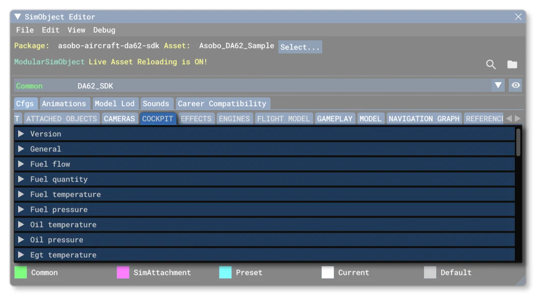
The cockpit.cfg is an optional file for SimObjects, unless you are creating an aircraft in which case it is mandatory. This file is used to define the different cockpit behaviors and instruments. Below you can find information on the different sections used in the cockpit.cfg file as well as what parameters and values are expected within them. Note that all these parameters can be edited directly in the simulation when Live Edition is enabled.
Many of the sections in this file use the following parameters to define the different colour ranges and markers that can be visible within the different displays. These are as follows:
Parameter
Description
Type
Required
min
These parameters define the different sections of the built-in cockpit display element. Not all displays use all these parameters, and each display will list the ones it uses in the descriptions provided.
If the display has any form of numeric display, the value units shown will depend on the display being set up - for example, a fuel gauge may use Gallons, while an Oil Temperature gauge may use degrees centigrade - however, a few displays have value units that are modifiable using the parameters in the [MISC] section.
All these parameters are 64bit floats, but the actual value you set should be appropriate for the display it pertains to.
Float
No
lowLimitlow_red_startlow_red_endlow_yellow_startlow_yellow_endwhite_startwhite_endgreen_startgreen_endyellow_startyellow_endred_startred_endhighLimitmax
[Version]
The [Version] section provides version information for the configuration file. In Microsoft Flight Simulator 2024, major versions should always be at least equal to 1.
Note that this section information is mandatory and should always be included.
| Parameter | Description | Type | Required |
|---|---|---|---|
major | Major CFG file version number, values must be greater than 0. | Integer | Yes |
minor | Minor CFG file version number, values must be greater than 0. | Integer | Yes |
[General]
This section contains the general parameters required by the file for cockpits.
| Parameter | Description | Type | Required |
|---|---|---|---|
cockpit_type | This tells the simulation the type of cockpit that aircraft has, and will be used to assign an appropriate cubemap to be used for reflections when the glass material has been used. See the modeling page on Translucent Elements for more information.
| Enum:
| Yes |

[FUEL_FLOW]
This section controls the fuel flow display. Uses:
minlowLimitgreen_startgreen_endhighLimitmax
[FUEL_QUANTITY]
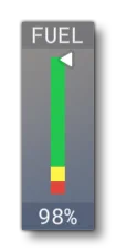
This section controls the fuel quantity display, which can be enabled/disabled using the hud_show_fuel parameter. Uses:
minlowLimitgreen_startgreen_endyellow_startyellow_endred_startred_endhighLimitmax
[FUEL_TEMPERATURE]
This section controls the display related to fuel temperature. Uses
minlowLimitlow_red_startlow_red_endlow_yellow_startlow_yellow_endgreen_startgreen_endyellow_startyellow_endred_startred_endhighLimitmax
[FUEL_PRESSURE]
This section controls the fuel pressure display. Uses:
minlowLimitlow_red_startlow_red_endlow_yellow_startlow_yellow_endgreen_startgreen_endyellow_startyellow_endred_startred_endhighLimitmax
[OIL_TEMPERATURE]
This section controls the oil temperature display. Uses:
minlowLimitlow_red_startlow_red_endlow_yellow_startlow_yellow_endgreen_startgreen_endyellow_startyellow_endred_startred_endhighLimitmax
[OIL_PRESSURE]
This section controls the oil pressure display. Uses:
minlowLimitlow_red_startlow_red_endlow_yellow_startlow_yellow_endgreen_startgreen_endyellow_startyellow_endred_startred_endhighLimitmax
[EGT_TEMPERATURE]
This section controls the exhaust gas temperature display. Uses
minlowLimithighLimitmax
[CHT_TEMPERATURE]
This section controls the CHT display. Uses:
minlowLimitgreen_startgreen_endyellow_startyellow_endred_startred_endhighLimitmax
[VACUUM]
This section controls the vacuum display. Uses:
minlowLimitgreen_startgreen_endhighLimitmax
[MANIFOLD_PRESSURE]
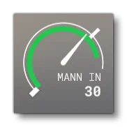
This section controls the manifold pressure display. It should be noted that this will be combined with the [RPM] display, and is only visible when the vcockpit_hud is set to 1 (TRUE). Uses:
minlowLimitgreen_startgreen_endhighLimitmax
[AIRSPEED]
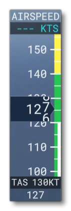
vcockpit_hud = 1
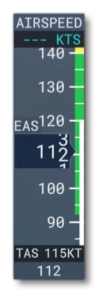
vcockpit_hud = 1equivalent_airspeed_hud = 1
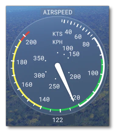
vcockpit_hud = 0
This section controls the airspeed indicator display, which will change depending on whether the vcockpit_hud is set to 1 (TRUE) or 0 (FALSE). Additionally, the Vcockpit HUD will change depending on the equivalent_airspeed_hud setting. Uses:
minlowLimitwhite_startwhite_endgreen_startgreen_endyellow_startyellow_endred_startred_endhighLimitmax
[TORQUE]
This section controls the torque indicator display. Uses:
minlowLimitgreen_startgreen_endyellow_startyellow_endred_startred_endhighLimitmax
[RPM]
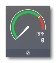
vcockpit_hud = 1
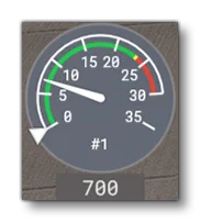
vcockpit_hud = 0
This section controls the RPM indicator display, which will change depending on whether the vcockpit_hud is set to 1 (TRUE) or 0 (FALSE). Note that when set to 1, you should also setup the [MANIFOLD_PRESSURE] values, as it will be displayed along with the RPM indicator. Uses:
minlowLimitgreen_startgreen_endyellow_startyellow_endred_startred_endhighLimitmax
[TURBINE_N1]
This section controls the turbine N1 indicator display. Uses:
minlowLimitgreen_startgreen_endyellow_startyellow_endred_startred_endhighLimitmax
[TURBINE_N2]
This section controls the turbine N2 indicator display. Uses:
minlowLimitgreen_startgreen_endyellow_startyellow_endred_startred_endhighLimitmax
[TURBINE_NG]
This section controls the turbine engine indicator display. Uses:
minlowLimitgreen_startgreen_endyellow_startyellow_endred_startred_endhighLimitmax
[ITTEngineOff]
This section controls the engine off display. Uses:
minlowLimitlow_red_startlow_red_endlow_yellow_startlow_yellow_endgreen_startgreen_endyellow_startyellow_endred_startred_endhighLimitmax
[ITTEngineOn]
This section controls the engine on display. Uses:
minlowLimitlow_red_startlow_red_endlow_yellow_startlow_yellow_endgreen_startgreen_endyellow_startyellow_endred_startred_endhighLimitmax
[MAIN_BUS_VOLTAGE]
This section controls the main bus voltage indicator display. Uses:
minlowLimitlow_red_startlow_red_endlow_yellow_startlow_yellow_endgreen_startgreen_endyellow_startyellow_endred_startred_endhighLimitmax
[HOT_BATTERY_BUS_VOLTAGE]
This section controls the hot battery bus voltage indicator display. Uses:
minlowLimitlow_red_startlow_red_endlow_yellow_startlow_yellow_endgreen_startgreen_endyellow_startyellow_endred_startred_endhighLimitmax
[BATTERY_BUS_AMPS]
This section controls the hot battery bus amps indicator display. Uses:
minlowLimitgreen_startgreen_endyellow_startyellow_endred_startred_endhighLimitmax
[GENALT_BUS_AMPS]
This section controls the generator alternator bus amps indicator display. Uses:
minlowLimitgreen_startgreen_endyellow_startyellow_endred_startred_endhighLimitmax
[COOLANT_LEVEL]
This section controls the coolant level indicator display. Uses
minlowLimithighLimitmax
[COOLANT_TEMPERATURE]
This section controls the coolant temperature indicator display. Uses:
minlowLimitlow_red_startlow_red_endlow_yellow_startlow_yellow_endgreen_startgreen_endyellow_startyellow_endred_startred_endhighLimitmax
[GEAR_OIL_TEMPERATURE]
This section controls the gear oil temperature display. Uses
minlowLimitgreen_startgreen_endyellow_startyellow_endred_startred_endhighLimitmax
[CABIN_ALTITUDE]
This section controls the cabin altitude indicator display. Uses:
minlowLimitgreen_startgreen_endhighLimitmax
[CABIN_ALTITUDE_CHANGE_RATE]
This section controls the cabin altitude change rate indicator display. Uses:
minlowLimithighLimitmax
[CABIN_PRESSURE_DIFF]
This section controls the cabin pressure differential display. Uses:
minlowLimitgreen_startgreen_endhighLimitmax
[HELICOPTER_ROTOR_RPM]
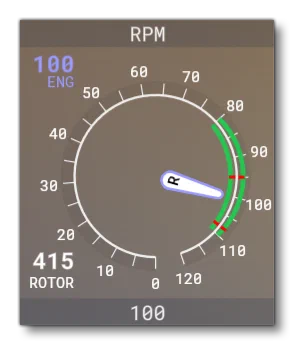
This section controls the rotor RPM indicator display when the aircraft is a rotorcraft. Uses:
minlowLimitgreen_startgreen_endyellow_startyellow_endred_startred_endhighLimitmax
[HELICOPTER_POWER]
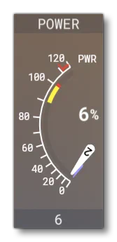
This section controls the display related to the power output when the aircraft is a rotorcraft. Uses:
minlowLimitlow_red_startlow_red_endlow_yellow_startlow_yellow_endgreen_startgreen_endyellow_startyellow_endred_startred_endhighLimitmax
[ATTITUDE_INDICATORS]
This section is used to define the characteristics of the attitude indicators on the instrument panels, where each indicator is defined in order, starting at 0 and incrementing by 1. Available parameters are:
| Parameter | Description | Type | Required |
|---|---|---|---|
attitude_indicator.N | The system which drives the attitude indicator. | Integer:
| No |
[TURN_INDICATORS]
This section controls the cockpit display turn indicators. Available parameters are:
| Parameter | Description | Type | Required |
|---|---|---|---|
turn_indicator.N | This parameter requires two values which define the system on which the turn indicators are dependent. The first value is for turn, the second for bank, and they should be set to one of the following values:
For example: You can define multiple turn indicators where N starts at | List of Floats | No |
[DIRECTION_INDICATORS]
This section controls the display direction indicators, not including the magnetic compass. Available parameters are:
| Parameter | Description | Type | Required |
|---|---|---|---|
direction_indicator.N | Sets the type of indicator. If the indicator is type 4, then there must be two entries separated by a comma - the indicator type, and the index of the indicator to which this one is slaved. | Integer, one of:
or List of 2 Integers:
| No |
induction_compass.N | Defines 1 or more induction compasses, where N starts at 0 and goes up to compass-number - 1. | Integer:
| No |
[AIRSPEED_INDICATORS]
This section is used to define the characteristics of the different airspeed indicators on the instrument panel, where these characteristics define the calibration between calibrated airspeed and indicated airspeed.
Available parameters are:
| Parameter | Description | Type | Required |
|---|---|---|---|
airspeed_indicator.N | This is a two value table used to define airspeed indicator N. The first parameter in the table is a scalar on the calibrated airspeed, and the second is an offset in knots, where the offset is applied first, then the scalar. By default the value for the scalar is 1.0 and the offset is 0.0. This means that by default the indicated airspeed will be equal to calibrated airspeed. There can be multiple entries for this parameter, one for each indicator, with N starting at | List of Floats | Yes |
[ALTIMETERS]
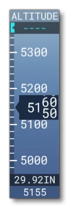
vcockpit_hud = 1
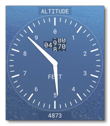
vcockpit_hud = 0
This section can be used to instantiate cockpit altimeters and set their position. Note that the look of the altimeter will change depending on whether the vcockpit_hud is set to 1 (TRUE) or 0 (FALSE). The section requires the parametrs in the table below.
| Parameter | Description | Type | Required |
|---|---|---|---|
altimeter.N | When set to TRUE (1), this will instantiate an altimeter, which will operate independently of other altimeters, and can have failures applied to it. There can be multiple entries for this parameter, one for each altimeter, with N starting at IMPORTANT! when referencing any altimeter using the appropriate SimVars (for example | Boolean | Yes |
altimeter_position.N | Sets the position of the altimeter N on the aircraft control panel using a table of values formatted as: Lateral, Vertical, Longitudinal. Values are relative to the Datum Reference Point. There can be multiple entries for this parameter, one for each altimeter, with N starting at 0 going up to number of altimeters - 1. | List of Floats | Yes |
[ANEMOMETERS]
This section controls the position of the cockpit anemometers. Available parameters are:
| Parameter | Description | Type | Required |
|---|---|---|---|
anemometer.N | Sets the position of the anemometer N on the aircraft control panel using a table of values formatted as: Lateral, Vertical, Longitudinal. Values are relative to the Datum Reference Point. There can be multiple entries for this parameter, one for each anemometer, with N starting at 0 going up to number of anemometers - 1. | List of Floats | Yes |
[MAGNETICCOMPASS]
This section controls the cockpit magnetic compass. Available parameters are:
| Parameter | Description | Type | Required |
|---|---|---|---|
compass.0 | Set to 1 for a vertical compass (with no dip errors). | Bool | No |
[VARIOMETERS]
This section controls the variometers for gliders. This is an instrument that helps you know when you’re in rising air and how strong the lift is. Unlike a vertical speed indicator in a powered aircraft, which indicates the vertical speed of the aircraft, a compensated variometer indicates the vertical speed of the airthrough which a glider is moving.
Available parameters are:
| Parameter | Description | Type | Required |
|---|---|---|---|
variometer.N | This sets up one or more variometers as part of the cockpit display. The parameter requires the following three values, given as a comma separated list:
For example: | List of Floats | No |
[GPWS]
This section controls the cockpit GPWS. Available parameters are:
| Parameter | Description | Type | Required |
|---|---|---|---|
max_warning_height | The height below which a warning is activated, in ft. | Float | Yes |
sink_rate_fpm | If an aircraft exceeds this rate of descent (in ft per minute) a warning is activated. | Float | Yes |
excessive_sink_rate_fpm | If an aircraft exceeds this rate of descent (in ft per minute) an urgent warning is activated. | Float | Yes |
climbout_sink_rate_fpm | If an aircraft starts to descend during takeoff, and exceeds this rate of descent (in ft per minute), a warning is activated. | Float | Yes |
flap_and_gear_sink_rate_fpm | If an aircraft is landing, and exceeds this rate of descent (in ft per minute) without flaps or gear extended, a warning is activated. | Float | Yes |
[THROTTLE_LEVELS]
This section controls the cockpit throttle levels. Available parameters are:
Parameter
Description
Type
Required
level_1_min
Set the minimum throttle percentage for each detent and the corresponding name. For example, for the A320, level 1 is -100 REV, level 2 is 0 IDLE, etc…
Available names are:
- “REV” - reverse
- “IDLE” - idle
- “A/THR” - auto
- “CL” - climb
- “FLX” - flex
- “TOGA” - toga
Default level is 0.
Default name is “”.
Float
Yes
level_1_name
String
Yes
level_2_min
Float
Yes
level_2_name
String
Yes
level_3_min
Float
Yes
level_3_name
String
Yes
level_4_min
Float
Yes
level_4_name
String
Yes
level_5_min
Float
Yes
level_5_name
String
Yes
level_6_min
Float
Yes
level_6_name
String
Yes
[FLAPS_LEVELS]
This section controls the cockpit flaps levels. Available parameters are:
Parameter
Description
Type
Required
slats_level_1
to
slats_level_10
The slats/flaps angle for each level in the flaps lever levels (in degrees).
Default values for both slats and flaps at all levels is 0, and setting a value greater than 0 will add a detent onto the display.
!
Float
No
flaps_level_1
to
flaps_level_10
Float
No
slats_level_full
Float
No
flaps_level_full
Float
No
[MISC]
This section controls certain HUD elements that will be visible when the user is in “3rd person mode” as well as the style that will be used to display them. Available parameters are:
Parameter
Description
Type
Required
equivalent_airspeed_hud
When this is is set to 1 (TRUE), airspeed will be shown as EAS., instead of IAS when 0 (FALSE).
vcockpit_hud is set to 1 (TRUE).Default value is 0 (FALSE).
Bool
No
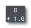
g_meter
When set to 1 (TRUE) a G-meter will be displayed on the external HUD, and if set to 0 (FALSE), none will be displayed.
Default value is (FALSE).
Bool
No
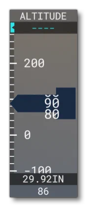
high_altitude_hud
When this is set to 1 (TRUE) and the vcockpit_hud parameter is also set to 1 (TRUE), then a larger altitude HUD display will be used. This is designed for aircraft that can go above 99,999 meters.
Bool
No
vcockpit_hud
This can be set to 1 (TRUE) to have a “vcockpit-style” digital external HUD, or it can be set to 0 (FALSE) to have a “steamgauge-style” analog external HUD. Note that many options will only have an effect on one or the other HUD type (these are flagged in their descriptions).
Default value is (FALSE).
Bool
No
gps_altimeter_hud
This can be used to enable (1, TRUE) or disable (0, FALSE) using GPS for the altitude indicator instead of the indicated altitude value (based on air pressure).
vcockpit_hud is set to 1 (TRUE).Default value is 0 (FALSE).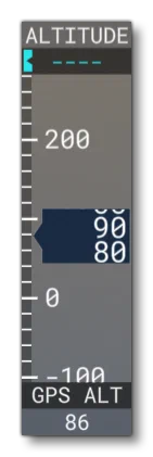
Bool
No
hud_airspeed_color_from_lvar
When defining your aircraft, you can select this option to set custom colours for the airspeed indicator using local variables, meaning that these colours can be changed dynamically using the using the “L:” var identifier in Reverse Polish Notation.
For this to work you need to define specifically named local variables that target the appropriate colour ranges in the indicator:
L:HUD_AIRSPEED_WHITE_START    // corresponds to the "white_start" parameter
L:HUD_AIRSPEED_WHITE_END      // corresponds to the "white_end" parameter
L:HUD_AIRSPEED_GREEN_START    // corresponds to the "green_start" parameter
L:HUD_AIRSPEED_GREEN_END      // corresponds to the "green_end" parameter
L:HUD_AIRSPEED_YELLOW_START   // corresponds to the "yellow_start" parameter
L:HUD_AIRSPEED_YELLOW_END     // corresponds to the "yellow_end" parameter
L:HUD_AIRSPEED_RED_START      // corresponds to the "red_start" parameter
L:HUD_AIRSPEED_RED_END        // corresponds to the "red_end" parameter
These L: vars can then be changed to adapt automatically to the aircraft dynamics. For example, the red section of the airspeed indicator on some aircraft is used to show the stall speed, and that stall speed changes when - for example - flaps are down, meaning that this can be reflected in the airspeed indicator using these variables.
vcockpit_hud is set to 1 (TRUE).Bool
No
hud_always_minimize_alt
When this is set to 1
\[TRUE\]the altitude gauge will be shown in its minimised form. When set to 0 (FALSE) or omitted, the gauge will be shown normally.
vcockpit_hud is set to 1 (TRUE).Default value is 0 (FALSE).
Bool
No
hud_always_minimize_ground_alt
When this is set to 1
\[TRUE\]the ground altitude gauge will be shown in its minimised form. When set to 0 (FALSE) or omitted, the gauge will be shown normally.
vcockpit_hud is set to 1 (TRUE).Default value is 0 (FALSE).
Bool
No
hud_always_minimize_gs
When this is set to 1
\[TRUE\]the ground altitude gauge will be shown in its minimised form. When set to 0 (FALSE) or omitted, the gauge will be shown normally.
vcockpit_hud is set to 1 (TRUE).Default value is 0 (FALSE).
Bool
No
hud_always_minimize_ias
When this is set to 1
\[TRUE\]the indicated airspeed gauge will be shown in its minimised form. When set to 0 (FALSE) or omitted, the gauge will be shown normally.
vcockpit_hud is set to 1 (TRUE).Default value is 0 (FALSE).
Bool
No
hud_always_minimize_pwr
When this is set to 1
\[TRUE\]the power gauge will be shown in its minimised form. When set to 0 (FALSE) or omitted, the gauge will be shown normally.
vcockpit_hud is set to 1 (TRUE).Default value is 0 (FALSE).
Bool
No
hud_always_minimize_vs
When this is set to 1
\[TRUE\]the vertical speed gauge will be shown in its minimised form. When set to 0 (FALSE) or omitted, the gauge will be shown normally.
vcockpit_hud is set to 1 (TRUE).Default value is 0 (FALSE).
Bool
No
hud_balloon_mode
When set to 1 (TRUE) the tachometer, airspeed, vertical speed, etc… will be displayed in a way more appropriate for a balloon.
Default value is 0 (FALSE).
Bool
No
hud_engine_throttle_var
This parameter allows you to assign a custom variable to drive the visual representation of the throttle position in the HUD instead of the default SimVar GENERAL ENG THROTTLE LEVER POSITION. This is only really necessary if there is any visual lag between the HUD throttle marker and the user input, and the variable can be a Local Var (L: or L:1), an InputVar (B:), or some other SimVar. For example:
hud_engine_throttle_var = L:Virtual_Throttle_Lever_PosNote that if you do not include the hud_engine_throttle_var_indexed parameter, then the variable will be for all engines.
String
No
hud_engine_throttle_var_indexed
This parameter is only used when hud_engine_throttle_var is defined. When set to 1 (TRUE), then the given variable will have an engine number appended onto it such that it will be used to control each engine HUD independently.
Bool
No
hud_helicopter_mode
When this is set to 1 (TRUE) and the vcockpit_hud parameter to be set to 0 (FALSE). the the engine display will be replaced by power and RPM displays. These can be setup using the [HELICOPTER_POWER] and [HELICOPTER_ROTOR_RPM] sections.
Default value is 0 (FALSE).
Bool
No
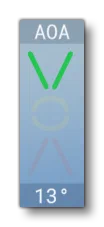
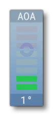
hud_navy_aoa
This can be used to enabled (1, TRUE) or disable (0, FALSE) the navy-style AoA indicator. Requires hud_show_aoa to be set to 1 (TRUE) - otherwise the AoA indicator will not be displayed - as well as the vcockpit_hud parameter to be set to 1 (TRUE).
Default value is 0 (FALSE).
Bool
No
hud_show_aoa
When set to 1 (TRUE) the HUD will display the AoA indicator.
Default value is 1 (TRUE).
Bool
No
hud_show_battery
When set to 1 (TRUE) the HUD will display the battery power indicator.
Default value is 0 (FALSE).

Bool
No
hud_show_fuel
When set to 1 (TRUE) the HUD will display the fuel meter. See [FUEL_QUANTITY] for more information.
Default value is 1 (TRUE).

Bool
No
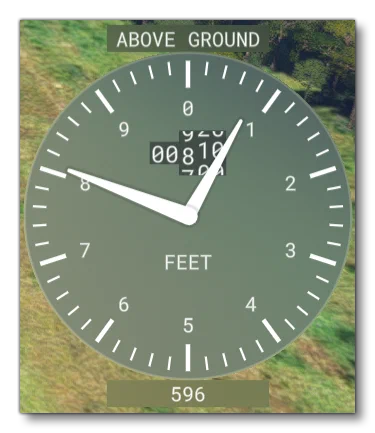
hud_show_ground_alt
When set to 1 (TRUE) the HUD will display the ground altitude indicator, but only when the vcockpit_hud parameter is set to 0 (FALSE).
Default value is 0 (FALSE).
Bool
No
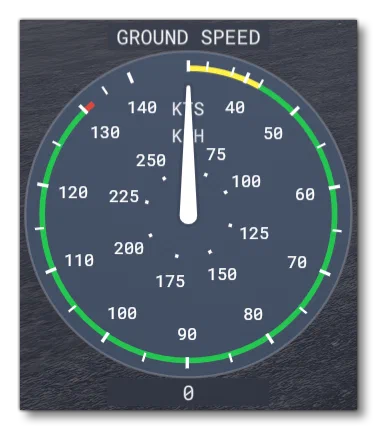
hud_show_gs
When set to 1 (TRUE) the HUD will display the ground speed indicator, but only when the vcockpit_hud parameter is set to 0 (FALSE). Note that the colour settings are taken from the [AIRSPEED] section.
Default value is 0 (FALSE).
Bool
No
hud_show_ias
When set to 1 (TRUE) the HUD will display the indicated airspeed indicator. The colour settings for this display are defined in the [AIRSPEED] section.
vcockpit_hud is set to 0 (FALSE), otherwise the airspeed indicator will always be shown.Default value is 0 (FALSE).
Bool
No
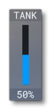
hud_show_liquid_tank
When set to 1 (TRUE) the HUD will display the liquid tank volume indicator. This is only appropriate if the aircraft has a \[Liquid Dropping System\].
Default value is 0 (FALSE).
Bool
No
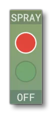
hud_show_spray_indicator
When set to 1 (TRUE) a spray indicator will be displayed on the external HUD, and if set to 0 (FALSE), none will be displayed.
Default value is 0 (FALSE).
Bool
No
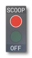
hud_show_scoop_indicator
When set to 1 (TRUE) a scoop indicator will be displayed on the external HUD, and if set to 0 (FALSE), none will be displayed.
Default value is 0 (FALSE).
Bool
No
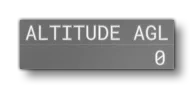
hud_show_radar_alt
When set to 1 (TRUE), a small altitude element will be added to the HUD, regardless of the HUD type. This displays the altitude above ground level, as returned by the onboard radar altimeter.
Bool
No
hud_show_tachometer
When set to 1 (TRUE) the HUD will display the tachometer. Note that visually this will change depending on whether the vcockpit_hud option is true or not.
For examples and setup information, please see the [MANIFOLD_PRESSURE] and [RPM] sections (when the vcockpit_hud option is true both of these sections will be used, and when false only the [RPM] section is used).
Default value is 1 (TRUE).
Bool
No
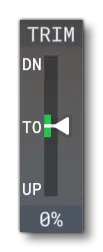
hud_show_trim
When set to 1 (TRUE) the HUD will show the trim display.
Default value is 1 (TRUE).
Bool
No
hud_show_vario
When set to 1 (TRUE) the HUD will display the variometer, which can be customised using the [VARIOMETERS] section. Note that this is only used by gliders, and will only show 0 for all other aircraft.
vcockpit_hud is set to 0 (FALSE).Default value is 0 (FALSE).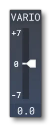
Bool
No
hud_speed_in_mach
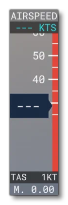
When set to 1 (TRUE) a mach speed will always be displayed on the external HUD, and if set to 0 (FALSE), then it won’t be displayed.
vcockpit_hud is set to 0 (FALSE).Default value is 0 (FALSE).
Bool
No
[TAKEOFF_SPEEDS]
This section is used to set certain takeoff speed values. Available parameters are:
| Parameter | Description | Type | Required |
|---|---|---|---|
take_off_speed_min_val | Default value is 0. | Integer | No |
take_off_speed_max_val | Default value is 0. | Integer | No |
take_off_speed_min_weight | Default value is 200. | Integer | No |
take_off_speed_max_weight | Default value is 1000000. | Integer | No |
[BALL_INDICATOR.N]
This section is used to set up the physics simulation to be used with a ball indicator model. In general we recommend that you use the Asobo_Turn_Coordinator_01 or Asobo_Turn_Coordinator_02 Included Attachments instead of creating your own, however if you wish to create your own models and add them, then the recommended model behaviour template is ASOBO_IT_Turn_Indicator_Template.
Available parameters are:
| Parameter | Description | Type | Required |
|---|---|---|---|
position | Sets the offset (x, y, z) - in ft - relative to the model center for the physics simulation to be placed. Default values are 0,0,0. | List of Floats | No |
radius | This defines the radius of curvature (bending) of the ball indicator tube. The value is in ft and must be greater than 0. Default value is 0.8. | Float | No |
length | This defines the length of the tube arc (ball path). The value is in ft and must be greater than 0, but cannot be greater than \(\pi \times \text{radius}\). Default value is 0.15. | Float | No |
angle | This defines the tilt (pitch angle) of the ball indicator relative to the aircraft body frame, in degrees (between -180, +180). This value is primarily used to set the angle of the ball when the dashboard surface is not totally vertical. Note too that a value of 180 will give you a ball indicator for inverted flight (which is used in aerobatic aircraft). Default value is 0. | Float | No |
damping_factor | This value is used to produce drag to slow the ball movement down, where the higher the value, the smoother (and slower) the ball will move. Default value is 70. | Float | No |
damping_power | This value is an exponential term used to modify the ball speed which makes the damping nonlinear (if set to a value other than 1). Default value is 1.5. | Float | No |
time_constant | This value is the time constant for the 2nd-order filter to smooth the local acceleration acting on the ball along the tube. The value is in seconds and must be greater than 0. Default value is 0.05. | Float | No |
Glass Cockpit Settings Struct
The contents of the cockpit.cfg file can be accessed from HTML gauges using JavaScript. In this case the returned value will be a struct (of the GlassCockpitSettings unit type) with the following contents:
RangeDisplay Struct
| Parameter | Default Value | Type |
|---|---|---|
__Type | “RangeDisplay” | String |
Initialized | true | Boolean |
min | 0 | Float |
max | 0 | Float |
lowLimit | 0 | Float |
highLimit | 0 | Float |
ColorRangeDisplay Struct
| Parameter | Default Value | Type |
|---|---|---|
__Type | “ColorRangeDisplay” | String |
Initialized | true | Boolean |
min | 0 | Float |
max | 0 | Float |
lowLimit | 0 | Float |
highLimit | 0 | Float |
greenStart | 0 | Float |
greenEnd | 0 | Float |
ColorRangeDisplay2 Struct
| Parameter | Default Value | Type |
|---|---|---|
__Type | “ColorRangeDisplay2” | String |
Initialized | true | Boolean |
min | 0 | Float |
max | 0 | Float |
lowLimit | 0 | Float |
highLimit | 0 | Float |
greenStart | 0 | Float |
greenEnd | 0 | Float |
yellowStart | 0 | Float |
yellowEnd | 0 | Float |
redStart | 0 | Float |
redEnd | 0 | Float |
ColorRangeDisplay3 Struct
| Parameter | Default Value | Type |
|---|---|---|
__Type | “ColorRangeDisplay3” | String |
Initialized | true | Boolean |
min | 0 | Float |
max | 0 | Float |
lowLimit | 0 | Float |
highLimit | 0 | Float |
greenStart | 0 | Float |
greenEnd | 0 | Float |
yellowStart | 0 | Float |
yellowEnd | 0 | Float |
redStart | 0 | Float |
redEnd | 0 | Float |
lowRedStart | 0 | Float |
lowRedEnd | 0 | Float |
lowYellowStart | 0 | Float |
lowYellowEnd | 0 | Float |
ColorRangeDisplay4 Struct
| Parameter | Default Value | Type |
|---|---|---|
__Type | “ColorRangeDisplay4” | String |
Initialized | true | Boolean |
min | 0 | Float |
max | 0 | Float |
lowLimit | 0 | Float |
highLimit | 0 | Float |
greenStart | 0 | Float |
greenEnd | 0 | Float |
yellowStart | 0 | Float |
yellowEnd | 0 | Float |
redStart | 0 | Float |
redEnd | 0 | Float |
whiteStart | 0 | Float |
whiteEnd | 0 | Float |
ThrottleLevelsInfo
| Parameter | Default Value | Type |
|---|---|---|
__Type | "ThrottleLevelsInfo" | String |
Initialized | true | Boolean |
minValues | [0, 0, 0, 0, 0] | Array (Floats) |
names | ["", "", "", "", ""] | Array (Strings) |
FlapsLevelsInfo
| Parameter | Default Value | Type |
|---|---|---|
__Type | "FlapsLevelsInfo" | String |
Initialized | true | Boolean |
slatsAngle | [0, 0, 0, 0] | Array (Floats) |
flapsAngle | [0, 0, 0, 0] | Array (Floats) |
TakeOffSpeedsInfo
| Parameter | Default Value | Type |
|---|---|---|
__Type | “FlapsLevelsInfo” | String |
Initialized | true | Boolean |
minVal | 0 | Float |
minWeight | 0 | Float |
maxVal | 200 | Float |
maxWeight | 1000000 | Float |
GlassCockpitMisc
| Parameter | Default Value | Type |
|---|---|---|
__Type | “GlassCockpitMisc” | String |
Initialized | true | Boolean |
hasGMeter | false | Boolean |