
flight_model.cfg
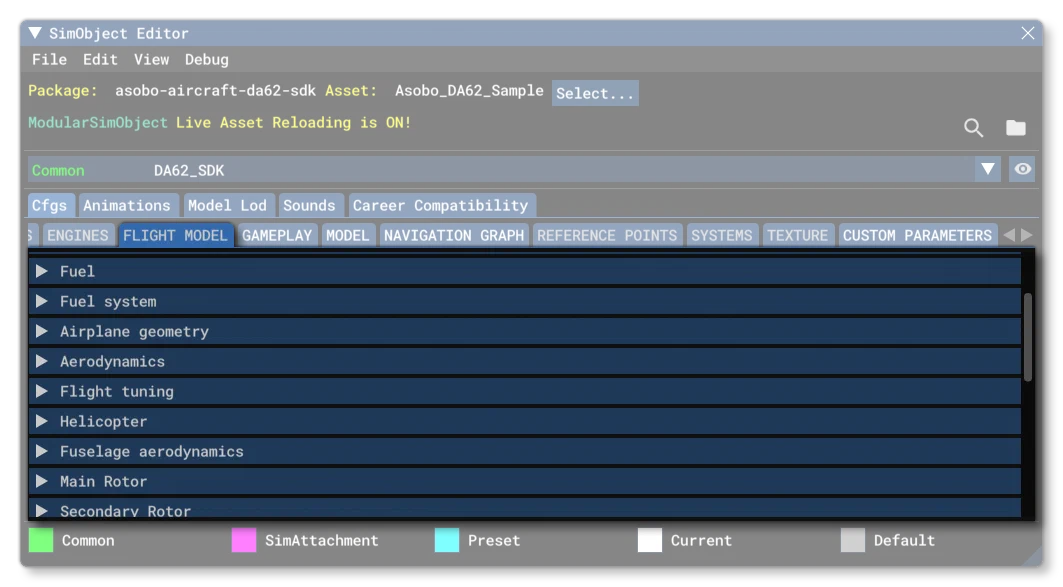
The flight_model.cfg file is an optional aircraft file for defining the flight model of the aircraft. In general, you’ll want to prepare this file using the DevMode tools (see here for more information) and then tweak the values if required in the CFG file.
Below you can find information on the different sections used in the flight_model.cfg file as well as what parameters and values are expected within them. You can also find an in-depth explanation of the physics behind the flight model from the following page:
To help with the configuration of the Flight Model (and the engines.cfg) we have included an *.xlsx file with the documentation that can be used to generate the required values for many of the parameters based on a small number of inputs (these inputs are marked in blue in the file):
[Version]
The [Version] section provides version information for the configuration file. In Microsoft Flight Simulator 2024, major versions should always be at least equal to 1.
Note that this section information is mandatory and should always be included.
| Parameter | Description | Type | Required |
|---|---|---|---|
major | Major CFG file version number, values must be greater than 0. | Integer | Yes |
minor | Minor CFG file version number, values must be greater than 0. | Integer | Yes |
[WEIGHT_AND_BALANCE]
This section is used to define the weight and balance of the aircraft. Most position parameters in this section are given relative to the Datum Reference Point for the aircraft, which is itself specified in this section. The convention for positions is that a positive value equals forward, to the right, or vertically upward, and note that all units are in ft, unless mentioned otherwise. Any 3D coordinates are given with respect to this referential in the following order:
z(longitudinal) coordinateX(lateral) coordinatey(vertical) coordinate
The only parameters that are not relative to the datum reference are the parameters for the manual longitudinal positioning of the CoL, compute_aero_center and aero_center_lift.
The available parameters for this section are:
| Parameter | Description | Type | Required |
|---|---|---|---|
max_gross_weight | The maximum total weight of the aircraft when fully loaded, in lbs. | Float | Yes |
max_zero_fuel_weight | The maximum weight of the aircraft when fully loaded but with empty fuel tanks, in lbs. Defaults to the max_gross_weight value if not supplied. | Float | No |
max_takeoff_weight | The maximum permitted takeoff weight of the aircraft, as defined by the aircraft manufacturer, in lbs.Defaults to the max_gross_weight value if not supplied. | Float | No |
max_landing_weight | The maximum permitted landing weight of the aircraft, as defined by the aircraft manufacturer, in lbs.Defaults first to max_takeoff_weight if a value is not supplied. If that paramater isn’t defined then it defaults to the max_gross_weight value. | Float | No |
empty_weight | The empty weight of the aircraft, in lbs. | Float | Yes |
reference_datum_position | The position of the Datum Reference Point relative to the model center. A three value list - z, x, y - with values in ft.IMPORTANT! The reference datum position should always be defined in the common folder of the modular aircraft, and it should not be changed by presets or attachments. Setting or changing the datum in presets or attachments may cause issues with multiple simulation systems. | List of 3 Floats | Yes |
empty_weight_CG_position | The position of airplane empty weight CG relative to the Datum Reference Point. A three value list - z, x, y - with values in ft. | List of 3 Floats | Yes |
CG_forward_limit | Forward limit of the CG as a Percent Over 100. For example, 0.11 is equal to 11% MAC.NOTE: This parameter is only valid for airplanes. | Float | Yes |
CG_aft_limit | Aft limit of the CG as a Percent Over 100. For example, 0.4 is equal to 40% MAC.NOTE: This parameter is only valid for airplanes. | Float | Yes |
CG_feet_forward_limit | The forward limit (longitudinal offset) of the CG expressed in ft from the Datum Reference Point.NOTE: This parameter is only valid for helicopters. | Float | Yes |
CG_feet_aft_limit | The aft limit (longitudinal offset) of the CG expressed in ft from the Datum Reference Point.NOTE: This parameter is only valid for helicopters. | Float | Yes |
CG_feet_lateral_right_limit | The right-side (lateral offset) limit of the CG expressed in ft from the Datum Reference Point.NOTE: This parameter is only valid for helicopters. | Float | Yes |
CG_feet_lateral_left_limit | The left-side (lateral offset) limit of the CG expressed in ft from the Datum Reference Point.NOTE: This parameter is only valid for helicopters. | Float | Yes |
empty_weight_pitch_MOI | The empty pitch MOI, in slug sqft.NOTE: This parameter will not be used if the empty_inertia_tensor parameter exists and has a valid setup. | Float | Yes |
empty_weight_roll_MOI | The empty roll MOI, in slug sqft.NOTE: This parameter will not be used if the empty_inertia_tensor parameter exists and has a valid setup. | Float | Yes |
empty_weight_yaw_MOI | The empty yaw MOI, in slug sqft.NOTE: This parameter will not be used if the empty_inertia_tensor parameter exists and has a valid setup. | Float | Yes |
empty_weight_coupled_MOI | The empty transverse MOI, in slug sqft.NOTE: This parameter will not be used if the empty_inertia_tensor parameter exists and has a valid setup. | Float | No |
empty_inertia_tensor | This is a list of between 3 and 6 values which are used to define the full inertia tensor of an empty aircraft relative to the aircraft center of gravity. The parameter definition takes the following format (all values are in slug sqft):empty_inertia_tensor = Jxx, Jyy, Jzz, Jyz, Jxz, JxyWhere:The first 3 values (Jxx, Jyy, Jzz) are mandatory. These are: - Jxx: the pitch moment of inertia around the lateral (X) axis. - Jyy: the yaw moment of inertia around the vertical (Y) axis. - Jzz: the roll moment of inertia around the longitudinal (Z) axis.The remaining 3 values (Jyz, Jxz, Jxy) are optional, and can be omitted - in order - from the end of the list. Omitted values are assumed to be 0. - Jxy (Jyx): centrifugal moment of inertia with respect to the lateral–vertical plane. - Jxz (Jzx): centrifugal moment of inertia with respect to the lateral–longitudinal plane. - Jyz (Jzy): centrifugal moment of inertia with respect to the longitudinal–vertical plane.For more information on the significance of these values and how they should be setup, please see here: Note On The Inertia TensorIMPORTANT! If this parameter is omitted or has invalid data, the empty_weight_pitch_MOI, empty_weight_roll_MOI, empty_weight_yaw_MOI, and the empty_weight_coupled_MOI parameters will be used instead. | List of 3 to 6 Values | No |
activate_mach_limit_based_on_cg | When set to TRUE (1) this activates mach limitation depending on CG position.Default for most aircraft is FALSE (0). | Bool | Yes |
activate_cg_limit_based_on_mach | When set to TRUE (1) this activate CG limitation depending on the mach value.Default for most aircraft is FALSE (0). | Bool | Yes |
max_number_of_stations | The maximum number of payload stations. | Integer | Yes |
station_load.N | This parameter can be used multiple times to define each of the payload stations up to the maximum defined by the max_number_of_stations value (note that counting starts at 0, so for 15 stations N would be from 0 to 14). The parameter takes a comma separated list with the following format:weight, z, x, y, name, typeThe weight is in lbs, (z, x, y) is the offset from the Datum Reference Point in ft, and the name is a localisable string. When it comes to type it can be omitted in most cases, but if included it can only be one of the following integer values (note that for Aircraft Loads this must be present and set to 6): - 0 (Unknown) - 1 (Pilot)- 2 (Copilot) - 3 (Passenger) - 4 (Front Passengers) - 5 (Rear Passengers) - 6 (Baggage)This parameter may be required if max_number_of_stations is greater than 0. | List of 5 or 6 Values | No |
station_name.N | This parameter defines a name that will be used in the payload dialog, and has a 15 character limit. Omission of this will result in a generic station name being used. This parameter can be used multiple times to define names for each of the payload stations up to the maximum defined by the max_number_of_stations value (note that counting starts at 0, so for 15 stations N would be from 0 to 14).This parameter may be required if max_number_of_stations is greater than 0. | String | No |
[CONTACT_POINTS]
This section is for defining the points on the aircraft body referential frame which are likely to come in contact with the ground. These parameters are used for aircraft positioning on the ground and also for crash simulations. Contact points should be added through the SimObject Editor, and only tweaked if required through the flight_model.cfg file.
This section has the following parameters:
| Parameter | Description | Type | Required |
|---|---|---|---|
max_water_depth | This parameter is used to set the maximum depth (in ft) up to which the SimObject will “sink” when on water.The value given cannot be below 2 (if set to less than 2, the simulation will use 2), and has a recommended maximum depth of no more than the aircraft (total visual mesh) length. However this value is uncapped and can be higher, but keep in mind that anything greater than the aircraft length will render the aircraft totally invisible when in the water and potentially cause issues with the camera.Default value is 2. | Float | No |
static_pitch | The pitch when at rest on the ground, in degrees, where a positive value is “up” and a negative value is “down”.IMPORTANT: Static pitch is only used when the physics simulation for the aircraft is not active: for example during certain RTC events. | Float | Yes |
static_cg_height | The altitude of the CG when at rest on the ground, in ft. This parameter is used in some checks to test if the aircraft is on ground or not, and can have unwanted side effects if not correctly configured (for example, ground services failing to work). | Float | Yes |
tailwheel_lock | Sets whether the tailwheel lock is available (TRUE, 1) or not (FALSE, 0). | Bool | Yes |
gear_system_type | Sets the gear system type for the aircraft. | Integer:0 = electrical1 = hydraulic2 = pneumatic3 = manual4 = none5 = undefined | Yes |
emergency_extension_type | Sets the type of emergency extension system that can be used. | Integer:0 = None1 = Pump2 = Gravity3 = Hydraulic backup reserve(Needs [HYDRAULIC_SYSTEM]) | Yes |
gear_locked_on_ground | Defines whether or not the landing gear handle is locked to down when the plane is on the ground (TRUE, 1) or not (FALSE, 0). | Bool | Yes |
gear_locked_above_speed | Defines the speed at which the landing gear handle becomes locked in the up position, in ft per second. Note that a value of -1 can be used to disable this option. | Float | Yes |
locked_tailwheel_max_range | This defines the maximum angle of the tailwheel when locked, in radians. Default is 0. | Float | Yes |
allow_stopped_steering | This can be used to enable (TRUE, 1) steering when the aircraft is stopped or not (FALSE, 0). | Bool | Yes |
max_speed_full_steering | Defines the speed under which the full angle of steering is available, in ft per second. | Float | Yes |
max_speed_decreasing_steering | Defines the speed above which the angle of steering stops decreasing, in ft per second. | Float | Yes |
min_available_steering_angle_pct | Defines the percentage of steering which will always be available even above max_speed_decreasing_steering, in percent over 100. | Float | Yes |
max_speed_full_steering_castering | Defines the speed under which the full angle of steering is available for free castering wheels, in ft per second. | Float | Yes |
max_speed_decreasing_steering_castering | Defines the speed above which the angle of steering stops decreasing for free castering wheels, in ft per second. | Float | Yes |
min_castering_angle | Defines the minimum angle a free castering wheel can take (in radians). | Float | Yes |
max_castering_angle | Defines the maximum angle a free castering wheel can take (in radians). | Float | Yes |
hyd_need_power_to_function | Sets whether the hydraulic systems for the landing gear require power to function (1, TRUE) or not (0, FALSE). Default value is 1, TRUE.NOTE: This parameter is only taken into consideration when the gear_system_type parameter is set to 1 (hydraulic). | Bool | Yes |
set_max_compression | This can be used to change the way how the 10th parameter in the point.N list will be used. If set to 1 (true) then the 10th parameter specifies the maximum compression of contact points (in feet) instead of their maximum-to-static compression ratio (which is by default, unitless).Default value is 0 (false). | Boolean | No |
point_order_independent_suspension_solver | When this is set to 1 (true), the simulation will find the frontmost and rearmost contact points simply based on their position relative to the Datum Reference Point. When set to 0 (false), the legacy method will be used (see the Note On Contact Point Order for details).Default is 0. | Boolean | No |
spring_exponential_fix | This parameter is only required to fix a potential issue related to the 17th parameter in the point.N definition, “Exponential Constant”. When this exponential constant is greater than 1, or very close to 1, the default algorithm lowers the spring force if compression is low. When this is set to 1 (TRUE), if the exponential constant is greater than 1 then it becomes the denominator for the linear spring force curve in the low compression range, and the power of this curve in the high compression range. For more information, see Notes On The Exponential Constant below.Default value is 0 (FALSE). | Bool | No |
water_longitudinal_friction_scalar | This parameter is a scalar used to modify the water friction for all contact points on the Z axis.Default value is 1. | Float | No |
water_lateral_friction_scalar | This parameter is a scalar used to modify the water friction for all contact points on the X axis.Default value is 1. | Float | No |
water_steering_friction_scalar | This parameter is a scalar used to modify the water friction on the X axis for water rudders.Default value is 1. | Float | No |
tailwheel_algo_detection | This parameter is used to define whether the aircraft contact points should use the legacy or modern description for tailwheel calculations outside of career activities. See the following section for more information:Note On TailwheelsDefault value is “Legacy”. | String: - Legacy - Modern | No |
point.N | Hashmap used to give the contact point a name and properties. This parameter can be used multiple times to define each of the contact points (note that counting starts at 0, so for 5 points N would be from 0 to 4). For the actual keys and values required, please see the table below. | Hash Map | No |
point.N
The point parameter is a hash map with the following keys:
| Key | Value | Description | Required |
|---|---|---|---|
Name | String | This is a name string that is used as an alias to identify the contact point. It will also be used as the reference index for SimVars, and note that the name is the only guaranteed reference to the component due to the fact that the Modular Aircraft Merging process may change the index. The name cannot contain special characters or spaces. | Yes |
WearAndTearGroup | Integer | This is used to assign the contact point being defined to a “group”. This is meant to be used for elements that require multiple contact points, but which are all part of a single structure. For example, you may use 3 contact points to define the left skid of an aircraft, and then assign all of them to the same wear and tear group. This means that all points in the group will be classed as a single element for tracking damage and wear and tear. | No |
Properties | List | Table that contains all the information about the contact point. | Yes |
The Properties key is a list of 20 values, as shown in the following example:
point.0 = Name: wheel1 #Properties: 1, -13, 0, -0.65, 750, 0, 0.523, 90, 0.296, 2.5, 0.794, 0, 0, 0, 165, 165, 1, 1, 0, -2.2Each of these property values is for a specific piece of information about the contact point, which we list in the table below for reference:
| List Position | Description | Type | Required |
|---|---|---|---|
| 0 | This sets the type of contact point being defined. Please refer to the following notes for additional information that will be important depending on the type of contact point being defined: - Note On Contact Point Order (only valid when point_order_independent_suspension_solver is false). - Note On Tailwheels - Notes On Skids - Notes On Floats - Note On Collision Damage / Wear And Tear (for scrape points) - Note On Advanced Ground Contact Model | Integer:1 = wheel2 = scrape points3 = skids4 = float5 = water rudder16 = ski17 = propeller18 = liquid dropping system scoop | Yes |
| 1 | Longitudinal position z relative to Datum Reference Point, in ft. This can be edited directly in the simulation when Live Edition is enabled. | Float | Yes |
| 2 | Lateral position x relative to Datum Reference Point, in ft. This can be edited directly in the simulation when Live Edition is enabled. | Float | Yes |
| 3 | Vertical position y relative to Datum Reference Point, in ft. This can be edited directly in the simulation when Live Edition is enabled. | Float | Yes |
| 4 | Impact damage threshold crash velocity, in ft per minute. | Float:-1 = Damage is automatically calculated by the simulation code.0 = The contact point is indestructible>0 = Sets a custom crash velocity for damage calculations. | Yes |
| 5 | The brake type the wheel contact uses. | Integer:1 = brake on left gear2 = brake on right gear3 = brake on both gears | Yes(if the position 0 contact value is 1 (for a wheel)) |
| 6 | The wheel radius, in ft. | Float | Yes(if the position 0 contact value is 1 (for a wheel)) |
| 7 | Wheel max steering angle, in degrees, between -90 and 90. | Float | Yes(if the position 0 contact value is 1 (for a wheel)) |
| 8 | The static compression coefficient constant (which is used to compute spring reaction when on the ground), in ft. If the contact point is rigid, then set this to 0.Please see Notes On Spring/Damping Factors for more information. | Float | Yes |
| 9 | If the set_max_compression parameter is set to 1 (true) then this specifies the maximum compression of the contact point, in feet. If the parameter is set to 0 (false) then this sets the maximum-to-static compression ratio for the contact point (a unitless value).Please see Notes On Spring/Damping Factors for more information. | Float | No |
| 10 | The damping ratio constant (used to compute ground reaction damping). A value between 0.0 (un-damped) and 1.0 (critically damped)Please see Notes On Spring/Damping Factors for more information. | Float | Yes |
| 11 | Extension time, in seconds. This is the time required to fully extend wheels/water rudder/skis/floats. | Float | Yes |
| 12 | Retraction time, in seconds. This is the time required to fully retract wheels/water rudder/skis/floats. | Float | Yes |
| 13 | Identifies the type of sound that is going to be played for the contact point. | Integer:0 = Center Gear1 = Auxiliary Gear2 = Left Gear3 = Right Gear4 = Fuselage Scrape5 = Left Wing Scrape6 = Right Wing Scrape7 = Aux1 Scrape8 = Aux2 Scrape9 = Tail Scrape | Yes |
| 14 | The airspeed limit for gears retraction, in kias. | Float | No |
| 15 | Airspeed above which gear is damaged, in kias.For more information see here: Landing Gear Damage. | Float | No |
| 16 | The exponential constant for springs (if in doubt, omit or set to 1). For more information, see Notes On The Exponential Constant. | Float | No |
| 17 | The extension mode to use for landing gear. This parameter defines how an extendable contact point should react to the gear handle moving, which can be one of the following values:0: manual - the gear goal will not follow the gear handle position (meaning that the “goal” position when extending/retracting the landing gear can be set from an external source)1: automatic - the gear goal will follow the gear handle positionIf omitted then the default behaviour will be automatic (1). | Bool | No |
| 18 | The airspeed above which the aircraft starts taking damage when the landing gear is in water, in kias.For more information see here: Landing Gear Damage. | Float | No |
| 19 | The airspeed above which the aircraft will receive catestrophic damage (ie: crash) when the landing gear is in water, in kias.For more information see here: Landing Gear Damage. | Float | No |
[COLLISION_DAMAGE]
This section is for defining the points on the aircraft body referential frame which are likely to come in contact with the ground. These parameters are used for aircraft positioning on the ground and also for crash simulations. Contact points should be added through the SimObject Editor, and only tweaked if required through the flight_model.cfg file. You can find additional information on how the wear and tear and collision damage parameters work from the following section:
This section has the following parameters:
| Parameter | Description | Type | Required |
|---|---|---|---|
CollisionDamage.N | This parameter is used to set up a collision “profile” which can be used elsewhere. This profile is comprised of the following key/value pairs:Name: The name of the profileContact Point: The name of the contact point to associate the profile with (must be of the type scrape point).Factor: The factor to multiply the damage from the contact point with.For example:CollisionDamage.0 = Name:LeftWingLightDamage # ContactPoint:Wing_Left # Factor:0.1Once you have this profile, you can assign it to various parts (as listed here) and if the contact point is involved in a collision, then damage will be propagated to the parts that reference the profile based on the factor used in the profile. A factor of 1 means that 100% of the damage will be propagated, and 0 means no damage will be propagated. | Hash Map | No |
AileronLeft | This is used to assign one or more damage profiles to the left aileron. The information is given as a hash map with the following key:WearAndTearCollision: A list of damage profile names, as defined in the CollisionDamage.N parameter, to associate with the aileron.For example:AileronLeft = WearAndTearCollision : LeftWingLightDamage, LeftWingHeavyDamage | Hash Map | No |
AileronLeftCable | This is used to assign one or more damage profiles to the left aileron control cable. The information is given as a hash map with the following key:WearAndTearCollision: A list of damage profile names, as defined in the CollisionDamage.N parameter, to associate with the aileron control cable.For example:AileronLeftCable = WearAndTearCollision : LeftWingLightDamage, LeftWingHeavyDamage | Hash Map | No |
AileronRight | This is used to assign one or more damage profiles to the right aileron. The information is given as a hash map with the following key:WearAndTearCollision: A list of damage profile names, as defined in the CollisionDamage.N parameter, to associate with the aileron.For example:AileronRight = WearAndTearCollision : RightWingLightDamage, RightWingHeavyDamage | Hash Map | No |
AileronRightCable | This is used to assign one or more damage profiles to the right aileron control cable. The information is given as a hash map with the following key:WearAndTearCollision: A list of damage profile names, as defined in the CollisionDamage.N parameter, to associate with the aileron control cable.For example:AileronLeft = WearAndTearCollision : RightWingLightDamage, RightWingHeavyDamage | Hash Map | No |
Rudder | This is used to assign one or more damage profiles to the rudder. The information is given as a hash map with the following key:WearAndTearCollision: A list of damage profile names, as defined in the CollisionDamage.N parameter, to associate with the rudder.For example:Rudder = WearAndTearCollision : LeftWingLightDamage, RightWingLightDamage | Hash Map | No |
RudderCable | This is used to assign one or more damage profiles to the rudder control cable. The information is given as a hash map with the following key:WearAndTearCollision: A list of damage profile names, as defined in the CollisionDamage.N parameter, to associate with the rudder control cable.For example:RudderCable = WearAndTearCollision : LeftWingLightDamage, RightWingLightDamage | Hash Map | No |
Elevator | This is used to assign one or more damage profiles to the elevator. The information is given as a hash map with the following key:WearAndTearCollision: A list of damage profile names, as defined in the CollisionDamage.N parameter, to associate with the elevator.For example:Elevator = WearAndTearCollision : LeftWingLightDamage, RightWingLightDamage | Hash Map | No |
ElevatorCable | This is used to assign one or more damage profiles to the elevator control cable. The information is given as a hash map with the following key:WearAndTearCollision: A list of damage profile names, as defined in the CollisionDamage.N parameter, to associate with the elevator control cable.For example:ElevatorCable = WearAndTearCollision : LeftWingLightDamage, RightWingLightDamage | Hash Map | No |
FlapsLeft | This is used to assign one or more damage profiles to the left flaps. The information is given as a hash map with the following key:WearAndTearCollision: A list of damage profile names, as defined in the CollisionDamage.N parameter, to associate with the left flaps.For example:FlapsLeft = WearAndTearCollision : LeftWingLightDamage, LeftWingHeavyDamage | Hash Map | No |
FlapsLeftCable | This is used to assign one or more damage profiles to the left flaps control cable. The information is given as a hash map with the following key:WearAndTearCollision: A list of damage profile names, as defined in the CollisionDamage.N parameter, to associate with the left flaps control cable.For example:FlapsLeftCable = WearAndTearCollision : LeftWingLightDamage, RightWingLightDamage | Hash Map | No |
FlapsRight | This is used to assign one or more damage profiles to the right flaps. The information is given as a hash map with the following key:WearAndTearCollision: A list of damage profile names, as defined in the CollisionDamage.N parameter, to associate with the right flaps.For example:FlapsRight = WearAndTearCollision : RightWingLightDamage, RightWingHeavyDamage | Hash Map | No |
FlapsRightCable | This is used to assign one or more damage profiles to the right flaps control cable. The information is given as a hash map with the following key:WearAndTearCollision: A list of damage profile names, as defined in the CollisionDamage.N parameter, to associate with the flaps control cable.For example:FlapsRightCable = WearAndTearCollision : LeftWingLightDamage, RightWingLightDamage | Hash Map | No |
LandingGear.N | This parameter permits you to assign a damage profile to one or more landing gear. The parameter is indexed from 1, and indices must be consecutive. Indices refer to a contact point of the type wheel where index 1 is the first one defined in the contact point section, regardless of it’s position in the contact point list. Index 2 wll be the second defined wheel, 3 the third, etc…The information for each landing gear is given as a hash map with the following key:WearAndTearCollision: A list of damage profile names, as defined in the CollisionDamage.N parameter.For example:LandingGear.1 = WearAndTearCollision:LeftWingLightDamage<span></span>LandingGear.2 = WearAndTearCollision:RightWingLightDamage | Hash Map | No |
Engine.N | This parameter permits you to assign a damage profile to one or more engines. The parameter is indexed from 1, and indices must be consecutive. Indices refer to the engine the profile should be applied to, counting from left to right.The information for each engine is given as a hash map with the following key:WearAndTearCollision: A list of damage profile names, as defined in the CollisionDamage.N parameter.For example:Engine.1 = WearAndTearCollision:LeftLightDamage<span></span>Engine.2 = WearAndTearCollision:RightLightDamage | Hash Map | No |
EngineOilTank.N | This parameter permits you to assign a damage profile to one or more engine oil tank. The parameter is indexed from 1, and indices must be consecutive. Indices refer to the engine the profile should be applied to.The information for each oil tank is given as a hash map with the following key:WearAndTearCollision: A list of damage profile names, as defined in the CollisionDamage.N parameter.For example:EngineOilTank.1 = WearAndTearCollision:LeftLightDamage<span></span>EngineOilTank.2 = WearAndTearCollision:RightLightDamage | Hash Map | No |
[FUEL]
This section is for defining a simplified fuel system that will reflect on the flight model. In general this section is where you’d define fuel systems for basic aircraft, but for more complex aircraft you have the [FUEL_SYSTEM] section which permits you to setup how fuel will be distributed and used within the aircraft on a much more detailed level. In the SimObject editor, this will only be visible if the Use Legacy Fuel option is checked.
This section has the following parameters:
| Parameter | Description | Type | Required |
|---|---|---|---|
LeftMain | Comma separated list of values that defines the tank. List values are:z, x, y, total_fuel_capacity, unusable_fuel_capacity(z, x, y) is offset from the Datum Reference Point and in ft, and the fuel capacity values are in Gallons. If any tank is not used, simply supply the list with all values set to 0. | List of 5 Values | Yes |
RightMain | Comma separated list of values that defines the tank. List values are:z, x, y, total_fuel_capacity, unusable_fuel_capacity(z, x, y) is offset from the Datum Reference Point and in ft, and the fuel capacity values are in Gallons. If any tank is not used, simply supply the list with all values set to 0. | List of 5 Values | Yes |
Center1 | Comma separated list of values that defines the tank. List values are:z, x, y, total_fuel_capacity, unusable_fuel_capacity(z, x, y) is offset from the Datum Reference Point and in ft, and the fuel capacity values are in Gallons. If any tank is not used, simply supply the list with all values set to 0. | List of 5 Values | Yes |
Center2 | Comma separated list of values that defines the tank. List values are:z, x, y, total_fuel_capacity, unusable_fuel_capacity(z, x, y) is offset from the Datum Reference Point and in ft, and the fuel capacity values are in Gallons. If any tank is not used, simply supply the list with all values set to 0. | List of 5 Values | Yes |
Center3 | Comma separated list of values that defines the tank. List values are:z, x, y, total_fuel_capacity, unusable_fuel_capacity(z, x, y) is offset from the Datum Reference Point and in ft, and the fuel capacity values are in Gallons. If any tank is not used, simply supply the list with all values set to 0. | List of 5 Values | Yes |
LeftAux | Comma separated list of values that defines the tank. List values are:z, x, y, total_fuel_capacity, unusable_fuel_capacity(z, x, y) is offset from the Datum Reference Point and in ft, and the fuel capacity values are in Gallons. If any tank is not used, simply supply the list with all values set to 0. | List of 5 Values | Yes |
LeftTip | Comma separated list of values that defines the tank. List values are:z, x, y, total_fuel_capacity, unusable_fuel_capacity(z, x, y) is offset from the Datum Reference Point and in ft, and the fuel capacity values are in Gallons. If any tank is not used, simply supply the list with all values set to 0. | List of 5 Values | Yes |
RightAux | Comma separated list of values that defines the tank. List values are:z, x, y, total_fuel_capacity, unusable_fuel_capacity(z, x, y) is offset from the Datum Reference Point and in ft, and the fuel capacity values are in Gallons. If any tank is not used, simply supply the list with all values set to 0. | List of 5 Values | Yes |
RightTip | Comma separated list of values that defines the tank. List values are:z, x, y, total_fuel_capacity, unusable_fuel_capacity(z, x, y) is offset from the Datum Reference Point and in ft, and the fuel capacity values are in Gallons. If any tank is not used, simply supply the list with all values set to 0. | List of 5 Values | Yes |
External1 | Comma separated list of values that defines the tank. List values are:z, x, y, total_fuel_capacity, unusable_fuel_capacity(z, x, y) is offset from the Datum Reference Point and in ft, and the fuel capacity values are in Gallons. If any tank is not used, simply supply the list with all values set to 0. | List of 5 Values | Yes |
External2 | Comma separated list of values that defines the tank. List values are:z, x, y, total_fuel_capacity, unusable_fuel_capacity(z, x, y) is offset from the Datum Reference Point and in ft, and the fuel capacity values are in Gallons. If any tank is not used, simply supply the list with all values set to 0. | List of 5 Values | Yes |
fuel_type | The fuel type for the engines. | Integer:1 = OCTANE 1002 = JET A3 = OCTANE 804 = AUTO GAS5 = JET B | Yes |
number_of_tank_selectors | The number of tank selectors available, between 1 and 4 only. | Integer | Yes |
electric_pump | Whether there is an electric pump (TRUE, 1) or not (FALSE, 0). | Bool | No |
engine_driven_pump | Whether there is an engine driven pump (TRUE, 1) or not (FALSE, 0). | Bool | No |
manual_transfer_pump | Whether there is a manual transfer pump (TRUE, 1) or not (FALSE, 0). | Bool | No |
manual_pump | Whether there is a manual pump (TRUE, 1) or not (FALSE, 0). | Bool | No |
anemometer_pump | Whether there is an anemometer pump (TRUE, 1) or not (FALSE, 0). | Bool | No |
fuel_dump_rate | The fuel dump rate, as a Percent Over 100. | Float | No |
max_pressure_auto_pump | The maximum pressure for the auto pump, in psi. | Float | No |
fuel_transfer_pump.N | Defines a fuel transfer pump N, where N starts at 0. Table contents are:lbsSource and Destination are one of the values given here for the different tanks: Fuel Tank Selection. The Pump ID is an integer value used to identify the pump and link it to a circuit.To toggle the pump on or off you need to have first created a circuit of the type CIRCUIT_FUEL_TRANSFER_PUMP using the circuit.N parameter of the systems.cfg file, and the circuit Type index needs to be the same as the Pump ID.The pump can then be toggled on/off using the FUEL_TRANSFER_CUSTOM_INDEX_TOGGLE key event, or using the ELECTRICAL_CIRCUIT_TOGGLE key event. | List of 4 Values | No |
default_fuel_tank_selector | The default fuel selector used in case of autostart, which will override default_fuel_tank_selector.N. | Integer:0 = Off1 = All2 = Left3 = Right4 = Left Aux.5 = Right Aux.6 = Center 17 = Center 28 = Center 39 = External 110 = External 211 = Right Tip12 = Left Tip13 = Crossfeed14 = Crossfeed Left-to-Right15 = Crossfeed Right-to-Left16 = Both17 = All External18 = Isolate19 = Left Main20 = Right Main | No |
default_fuel_tank_selector.N | Default fuel selector used in case of autostart for engine N, where N corresponds to an engine (between 1 and 4). This will be ignored if default_fuel_tank_selector is defined. | Integer:0 = Off1 = All2 = Left3 = Right4 = Left Aux.5 = Right Aux.6 = Center 17 = Center 28 = Center 39 = External 110 = External 211 = Right Tip12 = Left Tip13 = Crossfeed14 = Crossfeed Left-to-Right15 = Crossfeed Right-to-Left16 = Both17 = All External18 = Isolate19 = Left Main20 = Right Main | Yes |
fuel_tank_priority | This is a list of fuel tanks which determines the order in which the tanks are filled/emptied when adjusting levels in the UI or EFB, or when skipping part of the flight. The order is based on the order in which the tanks are listed, where the first tanks are those which are emptied first and filled last, and last tanks are those which are filled first and emptied last. for example:fuel_tank_priority = LeftMain-RightMain, Center1In this example both the left and right main tanks are priority 1, then Center1 is priority 2, so The Left and Right main tanks will be the first to be emptied. | List of Strings:Center1Center2Center3LeftMainLeftTipLeftAuxRightMainRightTipRightAuxExternal1External2 | No |
[FUEL_SYSTEM]
This section is for defining the aircraft’s fuel system in detail. In general, the fuel system should be set up through the SimObject Editor, and only tweaked if required through the flight_model.cfg file using the parameters on this page.
The [FUEL_SYSTEM] section is primarily for use in complex aircraft models where the simple [FUEL] system doesn’t give enough control or flexibility for the aircraft systems. The parameters within the [FUEL] section should be used for simple aircraft or those that require a basic fuel system setup, or for maintaining old aircraft (like ones imported from FSX).
This section only has a few parameters, but each parameter can be repeated a number of times if required, where N in the parameter name corresponds to a new item of that parameter type. For example, the Engine parameter can go from Engine.1 to Engine.4 and each one can be defined separately.
The available fuel system parameters are:
| Parameter | Description | Type | Required |
|---|---|---|---|
Version | This value corresponds to the various versions of the modern fuel system and is used to permit you to maintain compatibility with already published aircraft as the modern fuel system evolves. The following values are currently accepted:1: Uses the Fuel System as released in Microsoft Flight Simulator 2020 SimUpdate 8 - this was the initial release of the new fuel system and had a bug where (under some conditions) an aircraft would have “infinite” fuel.2: Uses the Fuel System as updated in Microsoft Flight Simulator 2020 SimUpdate 9 - this update fixed the infinite fuel bug, but had an issue with reduced fuel flow through junctions (under some conditions).3: Uses the Fuel System as updated in Microsoft Flight Simulator 2020 SimUpdate 10 - this update fixed the reduced fuel flow through junctions bug, however it had an issue loading and saving of junction settings inside of FLT files (sometimes it would save the wrong value which meant you would be on the wrong option when loading the file).4: Uses the Fuel System as updated in Microsoft Flight Simulator 2020 SimUpdate 11 - this update fixed the issue loading and saving junction setting inside of FLT files.5: Uses the Fuel System as updated in Microsoft Flight Simulator 2020 SimUpdate 14 - this update fixed the issue loading and saving junction setting inside of FLT files.6: Uses the Fuel System as updated in Microsoft Flight Simulator 2024 Initial Release - this update limits the framerate of the fuel system to 30fps to provide a more stable time interval. It also corrects the following bugs: bug that could cause junctions to seemingly “create” fuel an issue that could cause the engine to lose combustion when all the remaining fuel in a line could be used in a single frame some behavior issues using gravity based fuel flow.This version also supports reading the fuel_type CFG parameter directly within the [Fuel_System] section rather than relying on the [Fuel] section.7: Uses the Fuel System as updated in Microsoft Flight Simulator 2024 SimUpdate 3. This version fixes an issue which could mean the fuel system would cause the simulation to freeze when created with very specific layouts.8: This version adds “smoothing” to the fuel system pressure. This resolves an issue where stopping one pump and starting another could have a single frame before the where the pressure received by the engine was 0 as the pumps switched.Latest: Using this value means that the aircraft will always use the latest available version of the fuel system (currently the initially updated Microsoft Flight Simulator 2024 version). Note that using this option is potentially problematic when publishing an aircraft to the Marketplace, as it may mean that a future SimUpdate could break how the fuel system works. | String | Yes |
fuel_type | Sets the fuel type to be used by the engine or burner. This can be one of the following:0 - NONE1 - OCTANE 1002 - JET_A3 - OCTANE 804 - AUTO GAS5 - JET B6 - LIQUID PROPANE | Integer | Yes |
Burner.N | Defines one or more burners (up to a maximum of 16) that form a part of the fuel system. Details on the burner map contents are given here: Burner.NNote that burners require that the fuel_type be set to 6 (Liquid Propane). | Hash Map | No |
APU.N | This defines an APU for the fuel system. You can have multiple APU’s per system, numbered from 1 upwards. Details on the APU map contents are given here: APU.N | Hash Map | No |
Engine.N | Defines one or more engines (up to a maximum of 16) that form a part of the fuel system. Details on the engine map contents are given here: Engine.N | Hash Map | No |
Tank.N | Defines one or more fuel tanks that form a part of the fuel system. Details on the tank map contents are given here: Tank.N | Hash Map | No |
Line.N | Defines one or more lines that form a part of the fuel system. Details on the line map contents are given here: Line.N | Hash Map | No |
Junction.N | Defines one or more junctions that form a part of the fuel system. Details on the junction map contents are given here: Junction.N | Hash Map | No |
Valve.N | Defines one or more valves that form a part of the fuel system. Details on the valve map contents are given here: Valve.N | Hash Map | No |
Pump.N | Defines one or more fuel pumps that form a part of the fuel system. Details on the pump map contents are given here: Pump.N | Hash Map | No |
Trigger.N | Defines one or more triggers that will be used to change components within the fuel system based on certain conditions. Details on the trigger map contents are given here: Trigger.N | Hash Map | No |
Curve.N | A list of values. You can define multiple curves for a fuel system, starting at N = 1, and the curves may be used in multiple different parameters. Details on the list contents are given here: Curve.N | List of Values | No |
[AIRPLANE_GEOMETRY]
This section is for defining the geometry of an aircraft, which is an important part of the Microsoft Flight Simulator 2024 engine, since the flying physics will use, in a large part, the aircraft geometry to simulate the interaction between the SimObject and the physical world. In general, the geometry of the aircraft should be created and edited through the SimObject Editor, and only tweaked if required through the flight_model.cfg file.
Note that you can find further information on the physics behind this section from the following page:
You can also find a helpful tutorial on the basics of setting up the aircraft geometry from the following page:
The available parameters for the [AIRPLANE_GEOMETRY] section are:
| Parameter | Description | Type | Required |
|---|---|---|---|
wing_area | Total area of the top surface of the wing from tip-to-tip, in sqft. The wing area impacts the target lift and drag forces. For example it directly impacts lift proportionally to the area:\(L = 0.5 \times p \times v \times v \times WingArea \times C_L\) | Float | Yes |
wing_span | The horizontal distance between the two wing tips, in ft. The wing span impacts the distribution of the forces over the aircraft, and the larger the wing span the greater the increase in the roll and yaw moment of ailerons and also the resistance to the roll movement of the aircraft. | Float | Yes |
wing_root_chord | Length of the wing Chord at the intersection of the wing and the fuselage, in ft. The chord over the wing will be automatically computed based on the area, the span and the chord at the root. To get a rectangle shaped wing, enter the average chord into the root chord. To get a triangle shaped wing enter a root chord larger than the average chord. This value is used in the aerodynamic calculations. | Float | Yes |
wing_cg_refchord | This is the length of the wing reference chord, expressed in ft, with an enforced minimum value of 0.1. This chord value is only used to calculate %MAC in the EFB visual mass and balance representations.Default value when the parameter is not specified will be the mean chord, dynamically computed by the simulation based on other parameters. | Float | No |
wing_camber | The wing Camber, in degrees. Wing camber here means the difference in virtual incidence or slope between the back region of the wing and the front region of the wing. A wing with a lot of camber has a big curve while a wing with less camber is more streamlined. Wing camber mostly has an impact on the pitch moment generated at various wing incidences as well as on the position of the aerodynamic center. | Float | Yes |
wing_thickness_ratio | The wing local thickness, calculated as:\({\textrm{local\_chord}} (x) \times \textrm{wing\_thickness\_ratio}\)Where \(x = \textrm{lateral coord}\)Value is in ft. | Float | Yes |
wing_dihedral | This is the angle between the wing leading edge and a horizontal line parallel to the ground, as seen when looking at the front of an aircraft. Technically defined as the dihedral angle Lambda, in degrees. The wing dihedral impacts secondary effects such as induced roll and adverse yaw. | Float | Yes |
wing_virtualdihedral | Sets the “virtual” dihedral. This values is added to the actual dihedral value, but without moving the surface, proportional to the vertical position of the wing. Note that high wings have more positive virtual dihedral, and low wings have more negative virtual dihedral. You can use this parameter to simulate the pressure build up between wing and fuselage when side slipping.Default value is 5.0. | Float | No |
wing_incidence | This is the angle (in degrees) the mean wing Chord makes with a horizontal line parallel to the ground, as seen when looking at the side of an aircraft from the wing tip.This base wing incidence is calculated when the aircraft surfaces are initially “built” in the simulation and before the normalization of the lift table. The base incidence impacts the zero AoA lift and should be set as closely as possible to the real wing incidence so that the normalization has as little work to do in order to reach the target lift polar. The normalization will readjust this incidence in order to match the target lift coefficient. | Float | Yes |
wing_twist | This is the difference in wing incidence from the root Chord and the tip Chord of the wing (in degrees). Technically defined as the wing twist epsilon.Most aircraft have twisted wings in order to increase aileron authority close to and during a stall. This also causes higher incidences towards the root of the wing and will cause these regions to stall earlier, which will cause more symmetrical stalls. | Float | Yes |
oswald_efficiency_factor | The wing oswald efficiency factor (non dimensional) measures the aerodynamic efficiency of the wing, where a theoretically perfect wing will have a factor of 1.0.This is the “e” in:\(C_{Di} = \frac {(C_L)^2} {pi \times AR \times e}\)While the aspect ratio is defined by the geometry, this factor impacts the induced drag, and most planes have an oswald factor in the order of 0.7. | Float | Yes |
wing_winglets_flag | Sets whether the aircraft has winglets (TRUE, 1) or not (FALSE, 0). This parameter is not directly used to define the aircraft geometry, however if the aircraft goes through the normalization process that normalizes the performance to the desired drag, then that drag value will include the winglet drag if it is enabled using this parameter. | Bool | Yes |
wing_sweep | The angle of the wing with the lateral axis. This is the angle the leading edge of the wing makes with a horizontal line perpendicular to the fuselage, as seen when looking down on top of an aircraft (expressed in degrees).Wing sweep has an important impact on secondary effects but also on the location of the wing on the longitudinal axis. The wing will be positioned to align the default 25% aerodynamic center with the aero_center_lift value and a swept wing will have the root in front of the aerodynamic center while the tip will be in the back. The wing will be automatically skewed to align with the target aerodynamic center position. | Float | Yes |
wing_pos_apex_vert | Vertical (y) distance of the wing apex - as measured at the centerline of the aircraft - from the Datum Reference Point in ft. This distance is measured positive in the “up” direction. | Float | Yes |
wing_mindragincidence | This sets the aircraft AoA at which the wing’s parasitic drag is minimal (lift induced drag is always minimal when lift is minimal).Default value is 0. | Float | No |
htail_area | Area of the static part of the horizontal stabilizer (not counting the elevator area), in sqft. The horizontal stabilizer and elevator will be simulated as a single wing with surfaces positioned in a way that the overall incidence matches the current control surface deflection. This single surface will have the area of htail_area and elevator_area combined. However, we recommend entering the exact area of each surface. This area will impact the pitch moment caused by the elevator deflection as well as the pitch moment caused by the horizontal stabilizer. | Float | Yes |
htail_span | The horizontal span of the h-tail and elevator surface, in ft. A large h-tail span will impact the roll moment of the propeller wash but also resist the aircraft roll movement. | Float | Yes |
htail_pos_lon | Longitudinal (z) distance of the horizontal tail apex and elevator surface - as measured at the centerline of the aircraft - from the Datum Reference Point in ft. This distance is measured positive in the forward (aircraft nose) direction.The longitudinal position of the htail impacts the pitch moment of the htail and elevator surfaces. The htail force vectors should be aligned with the real surface. | Float | Yes |
htail_pos_vert | Vertical (y) distance of the horizontal tail apex and elevator surface - as measured at the centerline of the aircraft - from the Datum Reference Point in ft. This distance is measured positive in the “up” direction.Depending on the vertical position of the htail, it can get into turbulences created by the wing located in front of it. In extreme situations this can create a deep and unrecoverable stall. | Float | Yes |
htail_incidence | The default incidence of the htail and elevator surface combination. This is the angle the mean horizontal tail Chord makes with a horizontal line parallel to the ground, as seen when looking at the side of an aircraft from the horizontal tail tip (in degrees).The aircraft surfaces will be build with this default incidence setting and all performance normalization will be calculated with this incidence. This means that the target lift and drag coefficients will match the aircraft with this htail_incidence default elevator angle. Any other elevator angle will generate different drag and lift coefficients.We recommend setting the htail_incidence so that the aircraft flies level at cruise speed without any required elevator input and zero elevator trim. This means that the htail_incidence will be the neutral trim for cruise speed. By doing this the lift and drag coefficients of the aircraft will perfectly match the target values during cruise and the drag force will be the most accurate and match the target performance during cruise. This also means that during any other phase, the drag performance of the aircraft won’t perfectly match the target formula because of the added drag caused by the added elevator deflection required to maintain a level flight at any other speed. This target formula is expressed as:\({C_D} = {C_{D0}} + K(C_L - C_{L0})^{2}\)However, it is possible to chose a different speed than cruise and set the htail_incidence for that speed. | Float | Yes |
htail_sweep | This is the angle the horizontal tail leading edge makes with a horizontal line perpendicular to the fuselage, as seen when looking down on top of an aircraft (in degrees). | Float | Yes |
htail_thickness_ratio | The horizontal tail local thickness, calculated as:\({\textrm{local\_chord}} (x) \times \textrm{htail\_thickness\_ratio}\)Where \(x = \textrm{lateral coord}\)Value is in ft. | Float | Yes |
vtail_area | The fuselage-to-tip area of the static part of the vertical stabilizer (not counting the rudder area), in sqft. The vertical stabilizer and rudder will be simulated as a single wing with surfaces positioned in a way such that the overall incidence matches the current control surface deflection. This single surface will have the area of vtail_area and rudder_area combined. However, we recommend entering the exact area of each surface. This area will impact the yaw moment caused by the rudder deflection as well as the yaw moment caused by the vertical stabilizer. | Float | Yes |
vtail_span | The vertical tail span is the vertical distance from the vertical tail-fuselage intersection to the tip of the vertical tail, in ft.A large vtail span will impact the roll moment of the propeller wash but also resist the aircraft roll movement. It will also counter adverse yaw and counter induced roll during rudder inputs. | Float | Yes |
vtail_sweep | This is the angle the vertical tail leading edge makes with a vertical line perpendicular to the fuselage, as seen when looking at the side of the vertical tail (in degrees). | Float | Yes |
vtail_pos_lon | Longitudinal (z) position of the vtail and rudder surface - as measured at the centerline of the aircraft - from the Datum Reference Point in ft. This distance is measured positive in the forward (aircraft nose) direction.The longitudinal position of the vtail impacts the yaw moment of the vtail and rudder surfaces. The vtail force vectors should be aligned with the real surface. | Float | Yes |
vtail_pos_vert | Vertical position of the vtail and rudder surface - as measured at the centerline of the aircraft - from the Datum Reference Point in ft. This distance is measured positive in the “up” direction.Depending on the vertical position of the vtail, it can get into turbulences created by the wing located in front of it. The vertical position of the vtail will impact the roll moment created by the surface. | Float | Yes |
vtail_thickness_ratio | The vertical tail local thickness, calculated as:\({\textrm{local\_chord}} (x) \times \textrm{vtail\_thickness\_ratio}\)Where \(x = \textrm{lateral coord}\)Value is in ft. | Float | Yes |
fuselage_length | The fuselage length from nose to tail, in ft. | Float | Yes |
fuselage_diameter | The approximate fuselage diameter, in ft. This value is used to limit the the drone camera and for other things like POI notification placement, etc…If this parameter is not included in the file, then the diameter will be inferred from the wing mean chord length and other data. | Float | No |
fuselage_center_pos | The fuselage center from the Datum Reference Point, in ft. | List of 3 Floats | Yes |
fuselage_mindragincidence | Aircraft AoA at which the fuselage’s drag is minimal.Default value is 0. | Float | No |
cockpit_width | The approximate width of the cockpit area, in ft.If you include this parameter then you should also include the cockpit_height parameter. If neither are used, then the width/height will be inferred from the fuselage_diameter. | Float | No |
cockpit_height | The approximate height of the cockpit area, in ft.If you include this parameter then you should also include the cockpit_width parameter. If neither are used, then the width/height will be inferred from the fuselage_diameter. | Float | No |
elevator_area | Area of the moving part of the horizontal stabilizer (not counting the htail area), in sqft.The horizontal stabilizer and elevator will be simulated as a single wing with surfaces positioned in a way that the overall incidence matches the current control surface deflection. This single surface will have the area of htail_area and elevator_area combined. However, we recommend entering the exact area of each surface. This area will impact the pitch moment caused by the elevator deflection as well as the pitch moment caused by the horizontal stabilizer. | Float | Yes |
aileron_area | The top surface aileron area, in sqft. | Float | Yes |
aileron_to_elevator_gain | Scales the elevator deflection angle in relation to the aileron deflection angle.Default value is 0. | Float | No |
rudder_area | Area of the moving part of the vertical stabilizer (not counting the vtail area),in sqft.The vertical stabilizer and rudder will be simulated as a single wing with surfaces positioned in a way that the overall incidence matches the current control surface deflection. This single surface will have the area of vtail_area and rudder_area combined. However, we recommend entering the exact area of each surface. This area will impact the yaw moment caused by the rudder deflection as well as the yaw moment caused by the vertical stabilizer. | Float | Yes |
elevator_up_limit | Upper angular limit of the elevator and htail combined control surface, in degrees.This should be the maximum elevator deflection angle possible and will be scaled down by the elasticity table and the elevator_maxangle_scalar. | Float | Yes |
elevator_down_limit | Lower angular limit of the elevator and htail combined control surface, in degrees (absolute values only).This should be the maximum elevator deflection angle possible and will be scaled down by the elasticity table and the elevator_maxangle_scalar. | Float | Yes |
aileron_up_limit | Upper angular limit of the aileron and wing combined control surface, in degrees.This should be the maximum aileron deflection angle possible and will be scaled down by the elasticity table and the aileron_effectiveness. | Float | Yes |
aileron_down_limit | Lower angular limit of the aileron and wing combined control surface, in degrees (absolute values only).This should be the maximum aileron deflection angle possible and will be scaled down by the elasticity table and the aileron_effectiveness. An excessive aileron down limit may increase the chance of the related wing surface stalling. | Float | Yes |
aileron_to_rudder_scale | The aileron to rudder ratio, used to link the two.If set to a value other than 0, the rudder will be controlled by the aileron controller axis instead of the rudder controller axis. The scale defines the ratio between the aileron input applied to the rudder and the original aileron input. | Float | Yes |
aileron_span_outboard | The outboard aileron span, expressed as a Percent Over 100.This is the ratio of wing length from the tip to the end of the aileron surface. A larger aileron will increase the roll moment of aileron deflection, but it will also increase the local drag generated by aileron deflection. | Float | Yes |
rudder_limit | Angular limit in degrees (absolute values only) of the rudder and vtail combined control surface.This should be the maximum rudder deflection angle possible and will be scaled down by the elasticity table and the rudder_maxangle_scalar. | Float | Yes |
rudder_trim_limit | Angular limit in degrees (absolute values only) of the rudder trim.This deflection adds to the rudder deflection. This should be the maximum rudder trim deflection angle possible and will be scaled down by the elasticity table and the rudder_trim_effectiveness. | Float | Yes |
elevator_trim_limit | Angular limit in degrees of the elevator trim. This deflection adds to the elevator deflection. This should be the maximum elevator trim deflection angle possible and will be scaled down by the elasticity table and the elevator_trim_effectiveness. Note that this value can be overriden by the elevator_trim_up_limit and elevator_trim_down_limit parameters.If this value is omitted and the elevator_trim_up_limit and elevator_trim_down_limit have not been set, then the default behavior will be to have no elevator trim applied. | Float | No |
elevator_trim_neutral | For many aircraft this will be the take off trim setting. The aircraft will start with this trim setting when starting on the ground. This trim setting is not used for performance normalizations nor to achieve the target lift and drag values, and is used for indicators only. The htail_incidence will be used for performance normalization. | Float | Yes |
elevator_trim_up_limit | Set the upper limit of the elevator trim deflection that makes the aircraft pitch up, in degrees (absolute values only). Note that this will override the value set in elevator_trim_limit, and will be scaled down by the elasticity table and the elevator_trim_effectiveness.If this parameter is omitted, then the elevator_trim_limit value will be used, and if that parameter is also omitted, then the no elevator trim will be applied. | Float | No |
elevator_trim_down_limit | Set the lower limit of the elevator trim deflection that makes the aircraft pitch down, in degrees (absolute values only). Note that this value cannot be greater than the value set in elevator_trim_up_limit, and will override the value set in elevator_trim_limit. It will also be scaled down by the elasticity table and the elevator_trim_effectiveness.If this parameter is omitted, then the elevator_trim_limit value will be used, and if that parameter is also omitted, then the no elevator trim will be applied. | Float | No |
spoiler_limit | This sets the angular limit of the wing spoilers on an aircraft, in degrees (absolute values only), when the spoiler is in ground configuration.If this limit is 0, no spoilers exist for the aircraft. | Float | Yes |
air_spoiler_limit | Angular limit in degrees of the spoiler and wing combined control surface, in degrees (absolute values only) when the spoiler is in the air configuration.If this value is not set, then it will default to the spoiler_limit value. | Float | No |
spoilerons_available | Indicates whether the spoilers also behave as spoilerons for roll control (if spoilers are available): 0 = FALSE (no spoilerons) or 1 = TRUE.Spoilerons will add spoiler deflection to aileron deflection based on aileron_to_spoileron_gain and min_ailerons_for_spoilerons. | Bool | Yes |
aileron_to_spoileron_gain | Scales the spoileron deflection angle in relation to the aileron deflection angle set with min_ailerons_for_spoilerons (if spoilerons_available is TRUE).Default value is 0.3. | Float | No |
min_ailerons_for_spoilerons | This value is used to indicate at what minimum aileron deflection angle the spoilers become active for roll control, in degrees (absolute values only). Based on aileron_to_spoileron_gain, the value is given in radians.Default value is 0.174533. | Float | No |
min_flaps_for_spoilerons | This parameter is used to cancel the spoilerons below a certain level of flaps, since it is often the case with airliners that spoilerons are only active when the flaps are extended. In order to determine this, the simulation will check if the current leading edge flaps are extended at or more than the angle defined in this parameter (in radians). If yes, then the spoilerons are active. If no, then they are canceled.NOTE: if the aircraft being edited doesn’t have real leading-edge flaps, you may need to create a “fake” set of leading-edge flaps with system_type set to manual (or none) for it to work properly.Default value is 0, and all values must be positive. | Float | No |
spoiler_extension_time | Time, in seconds, necessary to fully extend the spoilers. | Float | Yes |
spoiler_handle_available | This is used to configure the airplane with manual controls for the spoiler deflections (TRUE, 1) or not (FALSE, 0). | Bool | Yes |
spoiler_disabled_by_flaps | If TRUE (1), the spoilers will automatically retract when the flaps are extended.Default is FALSE (0). | Bool | No |
auto_spoiler_auto_retracts | If TRUE (1), the spoilers will automatically retract when the plane speed goes below auto_spoiler_min_speed.Default is TRUE (1). | Bool | No |
auto_spoiler_available | Sets whether auto spoilers are available (TRUE, 1) or not (FALSE, 0). | Bool | Yes |
auto_spoiler_min_speed | The minimum speed (in Knots) at which auto spoiler can activate.Defaults to 0. | Float | No |
positive_g_limit_flaps_up | Flap positive load limit when up. This is the positive limit - in G’s - that is imposed on the aircraft when the flaps are up. The supplied value is multiplied by the load_safety_factor parameter before being compared to the current load factor to detect if the aircraft is beyond limits.Note that if this parameter is not included, then none of the G-Limit flaps parameter will be read and will simply use the default values.Default value is 4.The aircraft will crash if the load factor reaches the G limit calculated using this parameter (For more information please see here: Overstress Damage). An aircraft with a load factor hold fly by wire system, will respect these limits as load factor limits. | Float | No |
positive_g_limit_flaps_down | Flap positive load limit when down. This is the positive limit - in G’s - that is imposed on the aircraft when the flaps are down. The supplied value is multiplied by the load_safety_factor parameter before being compared to the current load factor to detect if the aircraft is beyond limits.Note that this parameter is only read when the positive_g_limit_flaps_up has been defined.Default value is 2.The aircraft will crash if the load factor reaches the G limit calculated using this parameter (For more information please see here: Overstress Damage). An aircraft with a load factor hold fly by wire system, will respect these limits as load factor limits. | Float | No |
negative_g_limit_flaps_up | Flap negative load limit when up. This is the negative limit - in G’s - that is imposed on the aircraft when the flaps are up. The supplied value is multiplied by the load_safety_factor parameter before being compared to the current load factor to detect if the aircraft is beyond limits.Note that this parameter is only read when the positive_g_limit_flaps_up has been defined.Default value is 1.5.The aircraft will crash if the load factor reaches the G limit calculated using this parameter (For more information please see here: Overstress Damage). An aircraft with a load factor hold fly by wire system, will respect these limits as load factor limits. | Float | No |
negative_g_limit_flaps_down | Flap negative load limit when down. This is the negative limit - in G’s - that is imposed on the aircraft when the flaps are down. The supplied value is multiplied by the load_safety_factor parameter before being compared to the current load factor to detect if the aircraft is beyond limits.Note that this parameter is only read when the positive_g_limit_flaps_up has been defined.flight_model.cfg/#Default value is 1.5.The aircraft will crash if the load factor reaches the G limit calculated using this parameter (For more information please see here: Overstress Damage). An aircraft with a load factor hold fly by wire system, will respect these limits as load factor limits. | Float | No |
load_safety_factor | The load safety factor value. | Float | Yes |
load_g_limiter_g | This is the multiplier on top of the design limits before which damage will begin to accrue. It is used by the autopilot and FBW systems as part of the pitch control limiter.Default value is 7.5. | Float | No |
flap_to_aileron_scale | The scale defines the ratio of aileron deflection based on flap deflection. Will deflect ailerons when flaps are extended. | Float | Yes |
fly_by_wire | Sets whether fly-by-wire is available (TRUE, 1) or not (FALSE, 0).A fly by wire control system disconnects the direct connection between yoke and rudder inputs and the control surfaces and adds a computer in between. This allows to activate control modes such as load factor hold.NOTE: When enabled your aircraft may use the [STALL PROTECTION] system. | Bool | Yes |
fly_by_wire_from_flaps | Set’s the fly-by-wire mode. When set to 0 (FALSE), the fly-by-wire will be in load factor hold mode above 50ft and in direct mode below 50ft. When set to 1 (TRUE), the fly-by-wire will be in load factor hold mode when flaps are retracted and in direct mode when flaps are extended.Default is 0 (FALSE). | Bool | No |
fly_by_wire_load_factor_normalize_bank | Default value is 1. | Bool | No |
elevator_elasticity_table | A table that allows you to scale down the elevator control surface deflection angle depending on the current dynamic pressure. The table has a maximum of 5 values and has the following format:dynamic_pressure:correction_factor,<span></span>dynamic_pressure:correction_factor,<span></span>etc...Pressure is expressed as psf and the yoke correction factor is a Percent Over 100.The dynamic pressure being airspeed dependent, this allows to reduce deflection based on speed. The [Dev Mode] aircraft debugging tools allow you to get the current dynamic pressure from the Speed debug window. The dynamic pressure can also be obtained with the following formula:\(\textrm{dynamicpressure} = 0.5 \times \textrm{airdensity} \times \textrm{airspeed} \times \textrm{airspeed}\)Default value is: 0.0:1.0 | 1D Curve of Floats | No |
aileron_elasticity_table | A table that allows you to scale down the aileron control surface deflection angle depending on the current dynamic pressure.The table has a maximum of 5 values and has the following format:dynamic_pressure:correction_factor,<span></span>dynamic_pressure:correction_factor,<span></span>etc...Pressure is expressed as psf and the yoke correction factor is a Percent Over 100.The dynamic pressure being airspeed dependent, this allows you to reduce deflection based on speed. The [Dev Mode] aircraft debugging tools allow you to get the current dynamic pressure from the Speed debug window. The dynamic pressure can also be obtained with the following formula:\(\textrm{dynamicpressure} = 0.5 \times \textrm{airdensity} \times \textrm{airspeed} \times \textrm{airspeed}\)Default value is: 0.0:1.0 | 1D Curve of Floats | No |
rudder_elasticity_table | A table that allows you to scale down the rudder control surface deflection angle depending on the current dynamic pressure. The table has a maximum of 5 values and has the following format:dynamic_pressure:correction_factor,<span></span>dynamic_pressure:correction_factor,<span></span>etc...Pressure is expressed as psf and the yoke correction factor is a Percent Over 100.The dynamic pressure being airspeed dependent, this allows to reduce deflection based on speed. The [Dev Mode] aircraft debugging tools allow you to get the current dynamic pressure from the Speed debug window. The dynamic pressure can also be obtained with the following formula:\(\textrm{dynamicpressure} = 0.5 \times \textrm{airdensity} \times \textrm{airspeed} \times \textrm{airspeed}\)Default value is: 0.0:1.0 | 1D Curve of Floats | No |
elevator_trim_elasticity_table | A table that allows you to scale down the elevator control surface deflection angle depending on the current dynamic pressure. The table has a maximum of 5 values and has the following format:dynamic_pressure:correction_factor,<span></span>dynamic_pressure:correction_factor,<span></span>etc...Pressure is expressed as psf and the yoke correction factor is a Percent Over 100.The dynamic pressure being airspeed dependent, this allows to reduce deflection based on speed. The [Dev Mode] aircraft debugging tools allow you to get the current dynamic pressure from the Speed debug window. The dynamic pressure can also be obtained with the following formula:\(\textrm{dynamicpressure} = 0.5 \times \textrm{airdensity} \times \textrm{airspeed} \times \textrm{airspeed}\)Default value is: 0.0:1.0 | 1D Curve of Floats | No |
controls_reactivity_scalar | The reactivity scalar for all controls, which can be used to adjust - at a global level - the responsiveness and behaviour of the control system. This value is clamped to a maximum of 1, regardless of what the actual input is set to. | Float | Yes |
control_aileron_forcebased | If set to 1 (True), the control surface deflection will be based on an optional force simulation. When this simulation is on, use the elasticity table only for actual elasticity simulation, not to also simulate input force limit, or there will be a redundancy.Default value is 0. | Boolean | No |
control_aileron_maxforce_student | Defines the maximum input force (in lbs) a student pilot is capable to hold.Default value is 10. | Float | No |
control_aileron_minforce_student | Defines the minimum input force (in lbs) below a student pilot will input to work against input lag causing motion resisting forces in the input.Default value is 1. | Float | No |
control_aileron_maxforce_pilot | Defines the maximum input force (in lbs) a pilot is capable to hold.Default value is 20. | Float | No |
control_aileron_minforce_pilot | Defines the minimum input force (in lbs) below a pilot will input to work against input lag causing motion resisting forces in the input.Default value is 2. | Float | No |
control_aileron_maxforce_testpilot | Defines the maximum input force (in lbs) a testpilot is capable to hold.Default value is 40. | Float | No |
control_aileron_minforce_testpilot | Defines the minimum input force (in lbs) below a test pilot will input to work against input lag causing motion resisting forces in the input.Default value is 4. | Float | No |
control_aileron_still_force_at_max | Defines the holding force (in lbs) required for a maximum deflection at zero airspeed.Default value is 1. | Float | No |
control_aileron_still_force_to_move | Defines the moving force (in lbs/ratio/second) required for change the control surface deflection at zero airspeed.Default value is 2. | Float | No |
control_aileron_dynpres_ratio_force_at_max | Defines ratio of the dynamic pressure that will be added to the required holding force in lbs.Example: With a ratio of 1.0 and a dynamic pressure of 100, 100lbs of holding force will be required to maintain a 100% deflection.Default value is 0.66. | Float | No |
control_aileron_dynpres_ratio_force_to_move | Defines ratio of the dynamic pressure that will be added to the required moving force in lbs/ration/second.Example: With a ratio of 0.1 and a dynamic pressure of 100, 10lbs of moving force will be required over 1 second to move the deflection to 100% over 1 second.Default value is 0.1. | Float | No |
control_aileron_neutral_return_force_scalar | Defines the scalar used on the force used to return the aileron to a neutral position.Default value is 1. | Float | No |
control_aileron_failed_hydraulic_weight | Defines the “dead” weight of the aileron when hydraulics have failed (in lbs). Set to -1 to disable.Default value is -1. | Float | No |
control_elevator_forcebased | If set to 1 (TRUE), the control surface deflection will be based on an optional force simulation. When this simulation is on, use the elasticity table only for actual elasticity simulation, not to also simulate input force limit, or there will be a redundancy.Default value is 0. | Boolean | No |
control_elevator_maxforce_student | Defines the maximum input force (in lbs) a student pilot is capable to hold.Default value is 20. | Float | No |
control_elevator_minforce_student | Defines the minimum input force (in lbs) below a student pilot will input to work against input lag causing motion resisting forces in the input.Default value is 2. | Float | No |
control_elevator_maxforce_pilot | Defines the maximum input force (in lbs) a pilot is capable to hold.Default value is 40. | Float | No |
control_elevator_minforce_pilot | Defines the minimum input force (in lbs) below a pilot will input to work against input lag causing motion resisting forces in the input.Default value is 4. | Float | No |
control_elevator_maxforce_testpilot | Defines the maximum input force (in lbs) a testpilot is capable to hold.Default value is 80. | Float | No |
control_elevator_minforce_testpilot | Defines the minimum input force (in lbs) below a test pilot will input to work against input lag causing motion resisting forces in the input.Default value is 8. | Float | No |
control_elevator_still_force_at_max | Defines the holding force (in lbs) required for a maximum deflection at zero airspeed.Default value is 2. | Float | No |
control_elevator_still_force_to_move | Defines the moving force (in lbs/ratio/second) required for change the control surface deflection at zero airspeed.Default value is 4. | Float | No |
control_elevator_dynpres_ratio_force_at_max | Defines ratio of the dynamic pressure that will be added to the required holding force in lbs.Example: With a ratio of 1.0 and a dynamic pressure of 100, 100lbs of holding force will be required to maintain a 100% deflection.Default value is 1.33. | Float | No |
control_elevator_dynpres_ratio_force_to_move | Defines ratio of the dynamic pressure that will be added to the required moving force in lbs/ratio/second.Example: With a ratio of 0.1 and a dynamic pressure of 100, 10lbs of moving force will be required over 1 second to move the deflection to 100% over 1 second.Default value is 0.2. | Float | No |
control_elevator_neutral_return_force_scalar | Defines the scalar used on the force used to return the elevator to a neutral position.Default value is 1. | Boolean | No |
control_elevator_failed_hydraulic_weight | Defines the “dead” weight of the elevator when hydraulics have failed (in lbs). Set to -1 to disable.Default value is -1. | Float | No |
control_rudder_forcebased | If set to 1 (TRUE), the control surface deflection will be based on an optional force simulation. When this simulation is on, use the elasticity table only for actual elasticity simulation, not to also simulate input force limit, or there will be a redundancy.Default value is 0. | Float | No |
control_rudder_maxforce_student | Defines the maximum input force (in lbs) a student pilot is capable to hold.Default value is 40. | Float | No |
control_rudder_minforce_student | Defines the minimum input force (in lbs) below a student pilot will input to work against input lag causing motion resisting forces in the input.Default value is 4. | Float | No |
control_rudder_maxforce_pilot | Defines the maximum input force (in lbs) a pilot is capable to hold.Default value is 80. | Float | No |
control_rudder_minforce_pilot | Defines the minimum input force (in lbs) below a pilot will input to work against input lag causing motion resisting forces in the input.Default value is 8. | Float | No |
control_rudder_maxforce_testpilot | Defines the maximum input force (in lbs) a testpilot is capable to hold.Default value is 160. | Float | No |
control_rudder_minforce_testpilot | Defines the minimum input force (in lbs) below a test pilot will input to work against input lag causing motion resisting forces in the input.Default value is 16. | Float | No |
control_rudder_still_force_at_max | Defines the holding force (in lbs) required for a maximum deflection at zero airspeed.Default value is 4. | Float | No |
control_rudder_still_force_to_move | Defines the moving force (in lbs/ratio/second) required for change the control surface deflection at zero airspeed.Default value is 8. | Float | No |
control_rudder_dynpres_ratio_force_at_max | Defines ratio of the dynamic pressure that will be added to the required holding force in lbs.Example: With a ratio of 1.0 and a dynamic pressure of 100, 100lbs of holding force will be required to maintain a 100% deflection.Default value is 2.66. | Float | No |
control_rudder_dynpres_ratio_force_to_move | Defines ratio of the dynamic pressure that will be added to the required moving force in lbs/ration/second.Example: With a ratio of 0.1 and a dynamic pressure of 100, 10lbs of moving force will be required over 1 second to move the deflection to 100% over 1 second.Default value is 0.4. | Float | No |
control_rudder_neutral_return_force_scalar | Defines the scalar used on the force used to return the rudder to a neutral position.Default value is 1. | Float | No |
control_rudder_failed_hydraulic_weight | Defines the “dead” weight of the rudder when hydraulics have failed (in lbs). Set to -1 to disable.Default value is -1. | Float | No |
[AERODYNAMICS]
This section is for defining the aerodynamics of an aircraft. In general, the aerodynamics of the aircraft should be created and edited through the SimObject Editor, and only tweaked if required through the flight_model.cfg file.
Note that you can find further information on the physics behind this section from the following page:
You can also find a helpful tutorial on the basics of setting up the aircraft geometry from the following page:
The available parameters in the [AERODYNAMICS] section are:
| Parameter | Description | Type | Required |
|---|---|---|---|
normalizationmethod | This parameter is used to select the normalization method for aircraft.If set to -1, it will disable any normalization and the aircraft will have the raw aerodynamic coefficients as set on the surfaces.If set to 0, normalization will be active such that the global drag and lift polars of the aircraft will be normalized to match the global aircraft drag and lift values defined in the flight_model.cfg.Default value is 0. | Integer | No |
CFD_EnableSimulation | This can be used to enable (1, TRUE) or disable (0, FALSE) the use of CFD within the simulation.Default value is 0 (FALSE).For more information, please see here: Debug Aircraft CFD. | Boolean | No |
CFD_ReinjectBody | This can be used to enable (1, TRUE) or disable (0, FALSE) the reinjection of the CFD output with that of the flight model, specifically affecting the airframe surface. Note that this needs to be set to 1 (TRUE) for CFD_ReinjectRotors, CFD_ReinjectVTailX, and CFD_ReinjectHTailY to work as well. If this is 0 (FALSE), then those parameters will have no effect.Default value is 0 (FALSE).For more information, please see here: Debug Aircraft CFD. | Boolean | No |
CFD_ReinjectRotors | This can be used to enable (1, TRUE) or disable (0, FALSE) the re-injection of the CFD output with that of the flight model for rotors/propellers. Note that this parameter will have no effect if the CFD_ReinjectBody parameter is not set to 1 (TRUE).Default value is 0 (FALSE).For more information, please see here: Debug Aircraft CFD.IMPORTANT! This requires that you have the prop_mod_use_modern parameter set to 1 (TRUE). | Boolean | No |
CFD_ReinjectVTailX | This can be used to enable (1, TRUE) or disable (0, FALSE) the re-injection of the CFD output with that of the flight model, specifically affecting the tail control surfaces. Note that this parameter will have no effect if the CFD_ReinjectBody parameter is not set to 1 (TRUE).Default value is 0 (FALSE).For more information, please see here: Debug Aircraft CFD. | Boolean | No |
CFD_ReinjectHTailY | This can be used to enable (1, TRUE) or disable (0, FALSE) the re-injection of the CFD output with that of the flight model, specifically affecting the tail control surfaces. Note that this parameter will have no effect if the CFD_ReinjectBody parameter is not set to 1 (TRUE).Default value is 0 (FALSE).For more information, please see here: Debug Aircraft CFD. | Boolean | No |
CFD_AirViscosity | Set the air viscosity when the CFD simulation is active. This is essentially the viscosity term of the Navier Stokes equations(opens in a new tab) used by the CFD simulation, and it sets the rate at which the airspeed of a voxel will tend to the average airspeed of the surrounding voxels.Default value is 0.05, and the value will only be used when the CFD_EnableSimulation parameter is set to 1 (TRUE).For more information, please see here: Debug Aircraft CFD. | Float | No |
CFD_AirInCompressibility | Set the air incompressibility when the CFD simulation is active. This is essentially the divergence term of the the Navier Stokes equations(opens in a new tab) used by the CFD simulation, and sets the rate at which the pressure of a voxel will be impacted by the local divergence.Default value is 1.0, and the value will only be used when the CFD_EnableSimulation parameter is set to 1 (TRUE).For more information, please see here: Debug Aircraft CFD. | Float | No |
CFD_VoxelSizeScale | Set the scale of the voxel volume for CFD simulation. At 1, this will create a volume that is 150% that of the aircraft wingspan, and the volume will be comprised of n³ voxels (where n is set by the CFD_VoxelNbVoxels parameter).Default value is 1.0, and it has a range between 0.1 and 10. Note that the value will only be used when the CFD_EnableSimulation parameter is set to 1 (TRUE).For more information, please see here: Debug Aircraft CFD. | Float | No |
CFD_VoxelNbVoxels | This can be used to set the number of voxels that will be cubed to make the sample volume for the CFD simulation.IMPORTANT! This may have a serious impact on performance if set to values greater than the default value, due to it currently having a time complexity of O(n3).Default value is 20.0, and it has a range between 8 and 40. Note that the value will only be used when the CFD_EnableSimulation parameter is set to 1 (TRUE).For more information, please see here: Debug Aircraft CFD. | Float | No |
CFD_GroundCollisionVoxelOffset | This parameter allows you to offset the ground collision vertically by N voxels. With a value of 0 voxels, the ground collision lets the air penetrate up to 1 voxel into the ground, ie: the ground is a “soft collision layer” of about 1 voxel thickness that starts at ground level and ends 1 voxel into the ground. By setting this to 1 voxel, the soft ground collision starts 1 voxel above the ground and stops airflow before it touches the ground. Adjusting this value will have an impact on the strength of the ground effect that is applied on the aircraft. It is worth noting that ground effect is calculated taking into account the ground conditions, so things like icing will have an effect on the drag and lift.Default value is 0.0, and the value will only be used when the CFD_EnableSimulation parameter is set to 1 (TRUE).For more information, please see here: Debug Aircraft CFD. | Float | No |
lift_coef_pitch_rate | Defines how much lift will be added to the overall lift formula based on the current pitch rotation speed.This is a legacy FSX parameter not used in the modern flight model. In the modern flight model this effect is natively obtained through aerodynamic simulation of the surfaces defined in the [AIRPLANE_GEOMETRY] section. | Float | Yes(if using legacy flight model,No otherwise) |
lift_coef_daoa | Defines how much lift will be added to the overall lift formula based on the current angle of attack variation rate.This is a legacy FSX parameter not used in the modern flight model. In the modern flight model this effect is natively obtained through aerodynamic simulation of the surfaces defined in the [AIRPLANE_GEOMETRY] section. | Float | Yes(if using legacy flight model,No otherwise) |
lift_coef_delta_elevator | Defines how much lift will be added to the overall lift formula based on the current elevator deflection angle.This is a legacy FSX parameter not used in the modern flight model. In the modern flight model this effect is natively obtained through aerodynamic simulation of the surfaces defined in the [AIRPLANE_GEOMETRY] section. | Float | Yes(if using legacy flight model,No otherwise) |
lift_coef_horizontal_incidence | Defines how much lift will be added to the overall lift formula based on the current yaw angle of the aircraft.This is a legacy FSX parameter not used in the modern flight model. In the modern flight model this effect is natively obtained through aerodynamic simulation of the surfaces defined in the [AIRPLANE_GEOMETRY] section. | Float | Yes(if using legacy flight model,No otherwise) |
lift_coef_flaps | Defines the lift coefficient that will be added to the target lift coefficient obtained with the lift_coef_aoa_table of the airplane when at maximum flap expansion. | Float | Yes |
lift_coef_spoilers | Defines the lift coefficient that will be added to the target lift coefficient obtained with the lift_coef_aoa_table of the aircraft when at maximum spoiler expansion on the ground. This allows you to correctly tune the spoilers for ground usage where there is very strong drag and very strong loss in lift. Essentially this is the coefficient for the deflection of 1 radian.The lift value is multiplied by the spoiler deflection in radians, so this coefficient is necessary to compensate for the scale by the deflection angle (also in radians), in order to reach 100%.NOTE: This value will also be used when the aircraft is airborne, unless the lift_coef_air_spoilers value is set. | Float | Yes |
lift_coef_air_spoilers | Defines the lift coefficient that will be added to the target lift coefficient obtained with the lift_coef_aoa_table of the aircraft when at maximum spoiler expansion in the air. This allows to correctly tune the spoiler behaviour in the air where you have strong drag, and little loss in lift. The lift value is multiplied by the spoiler deflection in radians, so this coefficient is necessary to compensate for the scale by the deflection angle (also in radians), in order to reach 100%.NOTE: This value overrides the value set by lift_coef_spoilers. | Float | No |
drag_coef_zero_lift | Defines the target drag of the airplane in clean configuration (ie: no propeller, no turbulence, no engine wash, no gears, no flaps, no spoilers, no deflections…), when there is zero lift. This is usually also called the \(C_{D0}\) or \(C_{DZeroLift}\). Zero lift may occur at an angle of attack of zero - reason for which \(C_{D0}\) is sometimes the drag at an AoA of 0 - but most of the time, zero lift occurs at an angle of attack that is negative and the \(C_{D0}\) does not correspond to the drag at AoA 0.In the legacy FSX flight model, this defines the actual \(C_{D0}\). In the modern flight model, this defines the target \(C_{D0}\) that will be distributed over all the surfaces of the aircraft when building the airplane used in the aerodynamic surface simulation. Once the aircraft is built, it will then be normalized to match exactly the target \(C_{D0}\). | Float | Yes |
drag_coef_flaps | Defines the target drag added when flaps are fully extended. In the legacy FSX flight model, this defines the actual flap drag. In the modern flight model, this defines the target flap drag that will be distributed over all the flap surfaces of the aircraft when building the airplane used in the aerodynamic surface simulation. Once the aircraft is built, it will then be normalized to match exactly the target flap drag. | Float | Yes |
drag_coef_gear | Defines the drag of the gears that will be applied at the location of the gear contact points and create the appropriate angular moment.If the aircraft features retractable gears, this coefficient will be zero once the gears are retracted. For non retractable gears this will always be present. All aircraft which feature gears, retractable or not, should define a drag coefficient for gears. This drag coefficient should not be baked into the drag_coef_zero_lift otherwise the gear angular moment calculations will be wrong. Also note that if the aircraft has no landing gear, this value will STILL have an effect and as such should be set to 0 in those cases. | Float | Yes |
drag_coef_spoilers | Defines the target drag added when spoilers are fully extended on the ground, where there is very strong drag and very strong loss in lift. The drag value is multiplied by the spoiler deflection in radians, so this coefficient is necessary to compensate for the scale by the deflection angle (also in radians), in order to reach 100%.NOTE: This value will also be used when the aircraft is airborne, unless the drag_coef_air_spoilers value is set.In the legacy FSX flight model, this defines the actual flap drag. In the modern flight model, this defines the target spoiler drag that will be distributed over all the spoiler surfaces of the aircraft when building the airplane used in the aerodynamic surface simulation. Once the aircraft is built, it will then be normalized to match exactly the target spoiler drag. | Float | Yes |
drag_coef_air_spoilers | Defines the target drag added when spoilers are fully extended in the air, where you have strong drag, and little loss in lift. The drag value is multiplied by the spoiler deflection in radians, so this coefficient is necessary to compensate for the scale by the deflection angle (also in radians), in order to reach 100%.NOTE: This value overrides the value set by drag_coef_spoilers. | Float | Yes |
StallDef_StartRatio | Ratio of the stall AoA at which the airflow will start detaching from the wing.Default value is: 0.9 | Float | No |
StallDef_EndRatio | Ratio of the stall AoA at which the airflow will be completely detached from the wing.Default value is: 1.1 | Float | No |
StallDef_CurvePower | Power of the ratio curve that controls the airflow detaching from the wing between start and end.Default value is: 0.8 | Float | No |
StallDef_minTransition | In Radians, minimum angle between the stall AoA at which the airflow starts detaching and at which it is fully detached.Default value is: 0.025 | Float | No |
StallDef_airflowdetachspeed | In ratios per second, speed at which the airflow will be detaching.Default value is: 1.0 | Float | No |
StallDef_airflowattachspeed | In ratios per second, speed at which the airflow will be attaching.Default value is: 1.0 | Float | No |
Stall_AileronAddIncidence | Degrees added to the stall AoA at the ailerons.Default value is: 0.0 | Float | No |
Stall_TipAddIncidence | Degrees added to the stall AoA at the wingtips.Default value is: 2.0 | Float | No |
Stall_TipAddTwist | Virtual added wing twist to reduce stall at the wingtips.Default value is: 2.5 | Float | No |
Stall_TipTwistScaleRatio | Scale ratio of the virtual added wing twist.Default value is: 0.9 | Float | No |
stallalpha | Defines the theoretical average alpha (AoA) at which the aircraft will stall, in degrees.If the parameter is omitted from the file, then - when the aircraft is first instantiated - the stall alpha is measured on the actual flight model by performing lift measures at various AoA to find the point where the lift goes down when the AoA goes up. This precalculated value will be used as the default value. | Float | No |
stallalpha_ff | Defines the theoretical average alpha (AoA) at which the aircraft will stall in full-flap configuration, in degrees.If the parameter is omitted from the file, then - when the aircraft is first instantiated - the stall alpha is measured on the actual flight model by performing lift measures at various AoA to find the point where the lift goes down when the AoA goes up. This precalculated value will be used as the default value. | Float | No |
fuselage_rigidity | This parameter sets the rigidity of the fuselage. If set to -1 then the fuselage will be considered as having “infinite” rigidity, while values greater than 0 will mean that applied forces will affect the airframe. The approximate value for this parameter can be calculated as follows:fuselage_rigidity = distance from the CG in ft at which a force applied yields 50% of it’s effect on the entire airframe after 1 second.Note that low rigidity will increase the aircraft oscillations, and if the rigidity is low enough for the time accumulation to correspond to the oscillation frequency, then you can even get a situation of resonance that will cause the entire airframe to “flutter” wildly.Default value is -1, and the value is in ft. | Float | No |
fuselage_max_rigidity | This value is used to reduce the oscillation amplitude of the airframe when in overspeed. The recommended value for this parameter is approximately 0.01% - 1% of the aircraft empty weight, for example a large aircraft like the 737 would have a value between 200 and 300, while a smaller aircraft like the C172 would have a value between 50 and 70.Default value is 0. | Float | No |
fuselage_inertia | This parameter sets the inertia for the fuselage, and works in harmony with the fuselage_rigidity parameter. However, if that parameter is less than or equal to zero, then this parameter will have no effect. Generally you want to set this to 1 to start with then tweak it up or down to get the aircraft behaviour that you require.Default value is 1. | Float | No |
fuselage_lateral_cx | Defines the perpendicular drag coefficient of the fuselage, which occurs when the airflow is going perpendicular to the front axis (ie: sideways - left to right or right to left). This coefficient has an impact on drag when side slipping, as well as a general impact on yaw stability and pitch stability. Faster aircraft with a larger Reynolds number should usually have a larger lateral fuselage \(C_x\).Please note that the drag calculation supposes that the fuselage shape seen from the side has the shape of a rectangle with skewed front and rear tips. A larger or smaller \(C_x\) may be necessary to compensate for different fuselage shapes. If the fuselage has edges and is different from a perfect cylinder, the \(C_x\) should be higher. If the fuselage’s area, when seen from the side, is smaller than the area of a skewed rectangle, the \(C_x\) should be smaller to compensate. A longer aircraft, with a higher l/d ratio, will have a higher \(C_x\). A shorter aircraft with a smaller l/d ratio, will have a smaller \(C_x\). Therefore, when choosing a \(C_x\) it is important to consider the Reynolds number and l/d ratio of the fuselage.Default is 0.4 - which is approximately the lateral drag of a cylinder with a Reynolds number of a small aircraft and a l/d ratio of about 5, compensated for the shape of most small aircraft fuselages. The value should usually fall between 0.2 and 1.2 for most aircraft (with a “soft” limit of 2, which would essentially be a box).NOTE: This parameter will be used as the default value within some of the surface \(C_x\) parameters when using the OBJ_EA1_FUSELAGE.N physics objects. | Float | No |
fuselage_vertical_cx | This parameter sets the aerodynamic friction of the top and bottom facing surfaces of the fuselage.Default value is 0.4.NOTE: This parameter will be used as the default value within some of the surface \(C_x\) parameters when using the OBJ_EA1_FUSELAGE.N physics objects. | Float | No |
fuselage_longitudinal_cx | This parameter sets the aerodynamic friction of the front and back facing surfaces of the fuselage.Default value is 0.16.NOTE: This parameter will be used as the default value within some of the surface \(C_x\) parameters when using the OBJ_EA1_FUSELAGE.N physics objects. | Float | No |
fuselage_detached_cx | This parameter sets the aerodynamic friction of the top and* bottom* facing surfaces of the fuselage when the AoA of the fuselage is high.Default value is 0.4.NOTE: This parameter will be used as the default value within some of the surface \(C_x\) parameters when using the OBJ_EA1_FUSELAGE.N physics objects. | Float | No |
fuselage_longitudinal_drag_efficiency_cx | This parameter sets the oswald efficiency factor for the front and back surfaces when the incidence increases (ie: induced drag).Default value is 1.0.NOTE: This parameter will be used as the default value within some of the surface \(C_x\) parameters when using the OBJ_EA1_FUSELAGE.N physics objects. | Float | No |
fuselage_orthogonal_drag_efficiency_cx | This parameter sets the oswald efficiency factor for the side surface when the incidence increases (ie: induced drag).Default value is 1.0.NOTE: This parameter will be used as the default value within some of the surface \(C_x\) parameters when using the OBJ_EA1_FUSELAGE.N physics objects. | Float | No |
presspt_fwd_Alpha0_pMAC | Defines an additional forward offset applied to the overall pressure center of the wing when the wing surface is at an AoA of 0. The offset is defined as a ratio of the local Mean Aerodynamic Chord and negative values indicate a backwards offset.Default value is 0. | Float | No |
presspt_fwd_AlphaStall_pMAC | Defines an additional forward offset applied to the overall pressure center of the wing when the wing surface is at an the stall AoA. The offset is defined as a ratio of the local Mean Aerodynamic Chord and negative values indicate a backwards offset.Default value is 0. | Float | No |
presspt_fwd_AlphaHiStall_pMAC | Defines an additional forward offset applied to the overall pressure center of the wing when the wing surface is at high above the stall AoA (during a stall). The offset is defined as a ratio of the local Mean Aerodynamic Chord, and negative values indicate a backwards offset.Default value is -0.25. | Float | No |
presspt_fwd_Spoilers | Defines an additional offset applied to the overall pressure center of the spoilers. Note that negative values indicate a backwards offset and positive values indicate a forward offset.Default value is 0. | Float | No |
buffetingscalar | This parameter allows you to scale the intensity of the approximations of the vibrations/turbulence effects that causes the aircraft/wing to shake when the aircraft stalls. Minimum value is 0.Default is 0.25. | Float | No |
side_force_slip_angle | Defines how much side force will be generated when the yaw angle is non zero (during a side slip).This is a legacy FSX parameter not used in the modern flight model. In the modern flight model this effect is natively obtained through aerodynamic simulation of the surfaces defined in the [AIRPLANE_GEOMETRY] section. In the modern flight model, use fuselage_lateral_cx to modify the side drag coefficient of the fuselage and rudder_lift_coef to modify the forces generated by the rudder. | Float | Yes |
side_force_roll_rate | Defines how much side force will be generated when the aircraft has some roll speed (during a roll).This is a legacy FSX parameter not used in the modern flight model. In the modern flight model this effect is natively obtained through aerodynamic simulation of the surfaces defined in the [AIRPLANE_GEOMETRY] section. In the modern flight model, the side force resulting from a roll is a complex combination of the effect of all the aircraft surfaces that cannot be directly controlled. Making sure the aircraft surfaces are correctly aligned and feature correct areas and coefficients will result in a realistic side force when rolling. | Float | Yes(if using legacy flight model,No otherwise) |
side_force_yaw_rate | Defines how much side force will be generated when the yaw angle is changing.This is a legacy FSX parameter not used in the modern flight model. In the modern flight model this effect is natively obtained through aerodynamic simulation of the surfaces defined in the [AIRPLANE_GEOMETRY] section. In the modern flight model, use fuselage_lateral_cx to modify the side drag coefficient of the fuselage and rudder_lift_coef to modify the forces generated by the rudder. | Float | Yes(if using legacy flight model,No otherwise) |
side_force_delta_rudder | Defines how much side force will be generated when the rudder is deflected.This is a legacy FSX parameter not used in the modern flight model. In the modern flight model this effect is natively obtained through aerodynamic simulation of the surfaces defined in the [AIRPLANE_GEOMETRY] section. In the modern flight model, use rudder_lift_coef to modify the forces generated by the rudder deflection. | Float | Yes(if using legacy flight model,No otherwise) |
pitch_moment_horizontal_incidence | Defines how much pitch moment will be generated when the aircraft is yawing.This is a legacy FSX parameter not used in the modern flight model. In the modern flight model this effect is natively obtained through aerodynamic simulation of the surfaces defined in the [AIRPLANE_GEOMETRY] section. In the modern flight model, use the rudder trim and, rudder area and rudder vertical position to modify the pitch moment generated generated by the rudder at zero deflection. | Float | Yes(if using legacy flight model,No otherwise) |
pitch_moment_delta_elevator | Defines how much pitch moment will be generated when the elevator is deflected.This is a legacy FSX parameter and the actual value here is not normally used in the modern flight model, but the sign of the value is used and it is necessary to set a value other than 0 for the autopilot (see the notes below). In the modern flight model the effect that this parameter is natively obtained through aerodynamic simulation of the surfaces defined in the [AIRPLANE_GEOMETRY] section. In the modern flight model, use the elevator_lift_coef, elevator longitudinal position and elevator area to adjust this effect.NOTE: The absolute value of this parameter is ignored by the modern flight model but it’s sign is used to invert the elevator input angle when it is negative. This may be useful for aircraft that need an inverted elevator (elevator in the front).NOTE: Even in the modern flight model, the autopilot system may still use this variable to calculate the elevator deflection necessary to find a required pitch moment. The PID will usually compensate for wrong values, but this variable cannot be set to zero or very far off and must be relatively close to reality. You can use the legacy flight model tool to calculate the correct value that will then usually work with the autopilot. | Float | Yes |
pitch_moment_delta_trim | Defines how much pitch moment will be generated when the elevator trim is deflected.This is a legacy FSX parameter not used in the modern flight model. In the modern flight model this effect is natively obtained through aerodynamic simulation of the surfaces defined in the [AIRPLANE_GEOMETRY] section. In the modern flight model, use the elevator_lift_coef, elevator longitudinal position and elevator area and scale the trim effect to adjust this effect. | Float | Yes(if using legacy flight model,No otherwise) |
pitch_moment_pitch_damping | Defines how much the pitch velocity will be dampened when the plane is pitching.This is a legacy FSX parameter not used in the modern flight model. In the modern flight model this effect is natively obtained through aerodynamic simulation of the surfaces defined in the [AIRPLANE_GEOMETRY] section. In the modern flight model, use the elevator_lift_coef, elevator longitudinal position, fuselage_lateral_cx, and elevator area to adjust this effect. The wings and even the rudder may also contribute to this effect. | Float | Yes(if using legacy flight model,No otherwise) |
pitch_moment_aoa_0 | Defines how much the pitch moment will be generated at AoA 0.This is a legacy FSX parameter not used in the modern flight model. In the modern flight model this effect is natively obtained through aerodynamic simulation of the surfaces defined in the [AIRPLANE_GEOMETRY] section. In the modern flight model, use the htail_incidence as the primary variable to impact the 0 AoA pitch moment. | Float | Yes(if using legacy flight model,No otherwise) |
pitch_moment_daoa | Defines how much the alpha velocity will be dampened when the plane is changing incidence.This is a legacy FSX parameter not used in the modern flight model. In the modern flight model this effect is natively obtained through aerodynamic simulation of the surfaces defined in the [AIRPLANE_GEOMETRY] section. In the modern flight model, use the elevator_lift_coef, elevator longitudinal position, fuselage_lateral_cx and elevator area to adjust this effect. The wings and even the rudder may also contribute to this effect. | Float | Yes(if using legacy flight model,No otherwise) |
pitch_moment_flaps | Defines how much pitch moment will be generated when the flaps will be deflected.This is a legacy FSX parameter not used in the modern flight model. In the modern flight model this effect is natively obtained through aerodynamic simulation of the surfaces defined in the [AIRPLANE_GEOMETRY] section. In the modern flight model, refer to the flaps documentation to see how to move the flap lift on the longitudinal axis in order to control the pitch moment at each flap level. | Float | Yes(if using legacy flight model,No otherwise) |
pitch_moment_gear | Defines how much the pitch moment will be generated because of the gears.This is a legacy FSX parameter not used in the modern flight model. In the modern flight model this effect is natively obtained through aerodynamic simulation of the surfaces defined in the [AIRPLANE_GEOMETRY] section. In the modern flight model, use the drag_coef_gear and the position of the gear contact points to change the angular moments generated by gears. | Float | Yes(if using legacy flight model,No otherwise) |
pitch_moment_spoilers | Defines how much pitch moment will be generated when the spoilers will be deflected.This is a legacy FSX parameter not used in the modern flight model. In the modern flight model this effect is natively obtained through aerodynamic simulation of the surfaces defined in the [AIRPLANE_GEOMETRY] section. In the modern flight model, this will be automatically simulated and there is no way yet to change the pitch moment generated by spoilers. It will be an automatic effect of the spoiler deflection and mostly dependent on the drag generated by the spoilers and the vertical position of the wings. | Float | Yes(if using legacy flight model,No otherwise) |
pitch_moment_delta_elevator_propwash | Defines how much pitch moment will be generated when the elevator is deflected and there is a propeller spinning (prop wash).This is a legacy FSX parameter not used in the modern flight model. In the modern flight model this effect is natively obtained through aerodynamic simulation of the surfaces defined in the [AIRPLANE_GEOMETRY] section. In the modern flight model this is automatically simulated based on how air is accelerated by the propeller and blown onto the control surfaces. However one can use the elevator_lift_coef, elevator longitudinal position and elevator area to adjust this effect. In the modern flight model, this effect only works if the propeller is blowing air onto the control surfaces. If the propeller is under a wing, far from any surface, this effect will not occur. | Float | Yes(if using legacy flight model,No otherwise) |
pitch_moment_pitch_propwash | Defines how much pitch moment will be generated when the plane is pitching and there is a propeller spinning (prop wash).This is a legacy FSX parameter not used in the modern flight model. In the modern flight model this effect is natively obtained through aerodynamic simulation of the surfaces defined in the [AIRPLANE_GEOMETRY] section. In the modern flight model this is automatically simulated based on how air is accelerated by the propeller and blown onto the control surfaces. However one can use the elevator_lift_coef, elevator longitudinal position and elevator area to adjust this effect. In the modern flight model, this effect only works if the propeller is blowing air onto the control surfaces. If the propeller is under a wing, far from any surface, this effect will not occur. | Float | Yes(if using legacy flight model,No otherwise) |
roll_moment_slip_angle | Defines how much roll moment will be generated when the aircraft is yawing or side slipping.This is a legacy FSX parameter not used in the modern flight model. In the modern flight model this effect is natively obtained through aerodynamic simulation of the surfaces defined in the [AIRPLANE_GEOMETRY] section. In the modern flight model, most of the roll will be induced by the difference in lift between one wing and the other, and the rudder will work against this effect. Adjust the shape of the wing via wing_sweep, wing_dihedral, wing_twist, wing_camber, the position of the wing, and the vertical position of the rudder, the rudder area and rudder lift coefficient to adjust this effect. Some of these parameters will work against each other. Induced roll is a very complex effect to balance which will depend on many factors. | Float | Yes(if using legacy flight model,No otherwise) |
roll_moment_roll_damping | Defines how much the roll speed will be dampened based on the current roll speed.This is a legacy FSX parameter not used in the modern flight model. In the modern flight model this effect is natively obtained through aerodynamic simulation of the surfaces defined in the [AIRPLANE_GEOMETRY] section. In the modern flight model, most of the roll damping will be the result of the wings, the elevator and the rudder resisting roll. You can also use roll_stability and roll_gyro_stability to add more roll damping. | Float | Yes(if using legacy flight model,No otherwise) |
roll_moment_yaw_rate | Defines how much roll moment will be generated when the aircraft is rotating around the yaw axis.This is a legacy FSX parameter not used in the modern flight model. In the modern flight model this effect is natively obtained through aerodynamic simulation of the surfaces defined in the [AIRPLANE_GEOMETRY] section. In the modern flight model, most of the roll will be induced by the difference in lift between one wing and the other, and the rudder will work against this effect. Adjust the shape of the wing via wing_sweep, wing_dihedral, wing_twist, wing_camber, the position of the wing, and the vertical position of the rudder, the rudder area and rudder lift coefficient to adjust this effect. Some of these parameters will work against each others. Induced roll is a very complex effect to balance which will depend on many factors. | Float | Yes(if using legacy flight model,No otherwise) |
roll_moment_spoilers | Defines how much roll moment will be generated when the spoilers will be deflected.This is a legacy FSX parameter not used in the modern flight model. In the modern flight model this effect is natively obtained through aerodynamic simulation of the surfaces defined in the [AIRPLANE_GEOMETRY] section. In the modern flight model, this will be automatically simulated and there is no way yet to change the roll moment generated by spoilers. | Float | Yes(if using legacy flight model,No otherwise) |
roll_moment_delta_aileron | Defines how much roll moment will be generated when the ailerons are deflected.This is a legacy FSX parameter not used in the modern flight model. In the modern flight model this effect is natively obtained through aerodynamic simulation of the surfaces defined in the [AIRPLANE_GEOMETRY] section. In the modern flight model, use the aileron_span_outboard, aileron_effectiveness and the aileron up and down angles to control this effect. | Float | Yes(if using legacy flight model,No otherwise) |
roll_moment_delta_rudder | Defines how much roll moment will be generated when the rudder is deflected.This is a legacy FSX parameter not used in the modern flight model. In the modern flight model this effect is natively obtained through aerodynamic simulation of the surfaces defined in the [AIRPLANE_GEOMETRY] section. In the modern flight model, most of the roll will be induced by the difference in lift between one wing and the other, and the rudder will work against this effect. Adjust the shape of the wing via wing_sweep, wing_dihedral, wing_twist, wing_camber, the position of the wing, and the vertical position of the rudder, the rudder area and rudder lift coefficient to adjust this effect. Some of these parameters will work against each other. Induced roll is a very complex effect to balance which will depend on many factors. | Float | Yes(if using legacy flight model,No otherwise) |
roll_moment_delta_aileron_trim_scalar | Defines how much roll moment will be generated when the aileron trim is are deflected.This is a legacy FSX parameter not used in the modern flight model. In the modern flight model this effect is natively obtained through aerodynamic simulation of the surfaces defined in the [AIRPLANE_GEOMETRY] section. In the modern flight model, use the aileron_span_outboard, aileron_trim_effectiveness and aileron up and down angles to control this effect. | Float | Yes(if using legacy flight model,No otherwise) |
yaw_moment_slip_angle | Defines how much yaw moment will be generated when the aircraft is yawing or side slipping.This is a legacy FSX parameter not used in the modern flight model. In the modern flight model this effect is natively obtained through aerodynamic simulation of the surfaces defined in the [AIRPLANE_GEOMETRY] section. In the modern flight model, use fuselage_lateral_cx to modify the side drag coefficient of the fuselage and rudder_lift_coef to modify the forces generated by the rudder. The longitudinal position of the fuselage and rudder will have a big impact on the yaw moment. If most of the fuselage is behind the CG, the fuselage will have a stabilizing effect. | Float | Yes(if using legacy flight model,No otherwise) |
yaw_moment_roll | Defines how much yaw moment will be generated when the aircraft has some roll speed (during a roll).This is a legacy FSX parameter not used in the modern flight model. In the modern flight model this effect is natively obtained through aerodynamic simulation of the surfaces defined in the [AIRPLANE_GEOMETRY] section. In the modern flight model, the yaw moment resulting from a roll is a complex combination of the effect of all the aircraft surfaces that cannot be directly controlled. Adjusting the rudder surface parameters will have the largest effect here but the wing will have an effect too. Making sure the aircraft surfaces are correctly aligned and feature correct areas and coefficients will result in a realistic yaw moment when rolling. | Float | Yes(if using legacy flight model,No otherwise) |
yaw_moment_yaw_damping | Defines how much the yaw speed will be dampened based on the current yaw speed.This is a legacy FSX parameter not used in the modern flight model. In the modern flight model this effect is natively obtained through aerodynamic simulation of the surfaces defined in the [AIRPLANE_GEOMETRY] section. In the modern flight model, most of the yaw damping will be the result of the rudder and fuselage, but the wings contribute as well. You can also use yaw_stability and yaw_gyro_stability to add more yaw damping. | Float | Yes(if using legacy flight model,No otherwise) |
yaw_moment_yaw_propwash | Defines how much yaw moment will be generated when the plane is yawing and there is a propeller spinning (prop wash).This is a legacy FSX parameter not used in the modern flight model. In the modern flight model this effect is natively obtained through aerodynamic simulation of the surfaces defined in the [AIRPLANE_GEOMETRY] section. In the modern flight model this is automatically simulated based on how air is accelerated by the propeller and blown onto the control surfaces. However one can use the rudder_lift_coef, rudder longitudinal position and rudder area to adjust this effect. In the modern flight model, this effect only works if the propeller is blowing air onto the control surfaces. If the propeller is under a wing, far from any surface, this effect will automatically not occur. | Float | Yes(if using legacy flight model,No otherwise) |
yaw_moment_delta_aileron | Defines how much yaw moment will be generated when the ailerons are deflected.This is a legacy FSX parameter not used in the modern flight model. In the modern flight model this effect is natively obtained through aerodynamic simulation of the surfaces defined in the [AIRPLANE_GEOMETRY] section. In the modern flight model, this will mostly be caused by a difference in drag between both wings because of the difference in airspeed between both wings and the difference in deflection of both ailerons. Use the aileron_up_drag_coef, aileron_down_drag_coef and aileron up & down angles to control this effect. | Float | Yes(if using legacy flight model,No otherwise) |
yaw_moment_delta_rudder | Defines how much yaw moment will be generated when the rudder is deflected.This is a legacy FSX parameter not used in the modern flight model. In the modern flight model this effect is natively obtained through aerodynamic simulation of the surfaces defined in the [AIRPLANE_GEOMETRY] section. In the modern flight model, use rudder_lift_coef to modify the moment generated by the rudder deflection. The longitudinal position of the rudder also plays an important role. | Float | Yes(if using legacy flight model,No otherwise) |
yaw_moment_delta_rudder_propwash | Defines how much yaw moment will be generated when the plane rudder is deflected and there is a propeller spinning (prop wash).This is a legacy FSX parameter not used in the modern flight model. In the modern flight model this effect is natively obtained through aerodynamic simulation of the surfaces defined in the [AIRPLANE_GEOMETRY] section. In the modern flight model this is automatically simulated based on how air is accelerated by the propeller and blown onto the control surfaces. However one can use the rudder_lift_coef, rudder longitudinal position and rudder area to adjust this effect. In the modern flight model, this effect only works if the propeller is blowing air onto the control surfaces. If the propeller is under a wing, far from any surface, this effect will automatically not occur. | Float | Yes(if using legacy flight model,No otherwise) |
yaw_moment_delta_rudder_trim_scalar | Defines how much yaw moment will be generated when the rudder trim is are deflected.This is a legacy FSX parameter not used in the modern flight model. In the modern flight model this effect is natively obtained through aerodynamic simulation of the surfaces defined in the [AIRPLANE_GEOMETRY] section. In the modern flight model, use the rudder_trim_effectiveness, rudder area and rudder max deflection to control this. | Float | Yes(if using legacy flight model,No otherwise) |
compute_aero_center | Defines if the aerodynamic center longitudinal position should be placed computationally or manually. In legacy FSX, the aerodynamic center was in a constant position and computed based on the pitch moment data and moment of inertia values. This would still work with the modern flight model, but we recommend disabling the computation of the aerodynamic center - setting it to 0 (FALSE) - and positioning this manually with aero_center_lift. | Float | Yes |
aero_center_lift | When compute_aero_center is set to 0 (FALSE) this variable allows you to define the longitudinal position of the aerodynamic center, expressed in ft. The modern flight model does not force the position of the aerodynamic center during the simulation because the aerodynamic center is not static in this flight model - it is calculated as the result of complex pressure forces applied on the surfaces, which actually causes a moving aerodynamic center. It is, however, usually very close to 25% and will normally move between 20% and 30%. So, we use this variable to longitudinally align the wing surfaces with the wing geometry, considering that the aerodynamic center is located at 25% MAC. Again, this does not mean that the aero center will then stay at 25% MAC during the simulation, it will just be used to initialize the surface position once at start.IMPORTANT! This is positioned relative to the (0,0,0) position in the 3D model reference, **not **the Reference Datum position. | Float | Yes |
aileron_up_drag_coef | Defines the drag added by upwards aileron deflection. This parameter has a significant impact on adverse yaw. Reduce upward deflection drag to get more adverse yaw. This parameter is multiplied by the aileron deflection angle and internal coefficients.Default is 0.5. This can be scaled with the aileron_up_drag_scalar parameter in the [FLIGHT_TUNING] section and is further modified by internal coefficients. | Float | No |
aileron_down_drag_coef | Defines the drag added by upwards aileron deflection. This parameter has a significant impact on adverse yaw. Increase downward deflection drag to get more adverse yaw. This parameter is multiplied by the aileron deflection angle.Default is 1. This can be scaled with the aileron_down_drag_scalar parameter in the [FLIGHT_TUNING] section and is further modified by internal coefficients. | Float | No |
elevator_lift_coef | Defines the lift coefficient slope of the elevator control surface. This will have a direct impact on elevator authority and pitch stability. The elevator lift coefficient slope is usually dependent on the elevator aspect ratio.Default is 5.0, and generally values will always fall between 1.0 and 5.0, with a theoretical maximum of 2𝝅 and a recommended value between 2.0 (for less authority and stability) and 5.0 (for more authority and stability). This can be scaled with the elevator_effectiveness parameter in the [FLIGHT_TUNING] section. | Float | No |
rudder_lift_coef | Defines the lift coefficient slope of the rudder control surface. This will have a direct impact on rudder authority, yaw stability, adverse yaw and induced roll. The rudder lift coefficient slope is usually dependent on the rudder aspect ratio.Default is 5.0, and generally values will always fall between 1.0 and 5.0, with a theoretical maximum of 2𝝅 and a recommended value between 2.0 (for less authority and stability) and 5.0 (for more authority and stability). This can be scaled with the rudder_effectiveness parameter in the [FLIGHT_TUNING] section. | Float | No |
lift_coef_aoa_table | This table allows you to define the AoA polar (in radians) against the clean aircraft lift coefficient. The AoA vs. lift table defines how much lift the aircraft generates at various AoAs. The table has a maximum of 47 entries with the following format:AoA_alpha:lift_coef,<span></span>AoA_alpha:lift_coef,<span></span>AoA_alpha:lift_coef,<span></span>etc...In the modern flight model, this is used during the aircraft surfaces construction as a lift target that the aircraft should achieve at various angles of attack. This will impact the wing surfaces only, but the total lift will consider all surfaces. It describes the lift in clean configuration (ie: zero slip, no propeller, no gears, no control surface deflection). Once the aircraft is created, if will be normalized so that the effective lift coefficients measured actually match the target lift coefficients.NOTE: The lift coefficients are only matched between AoAs 0 and the stall AoA. For other AoAs all around the 360° of the polar, it will be a natural consequence of the setup of the aerodynamic surfaces and other parameters. The polar does not need to be accurately defined in detail for AoAs outside of the -10° to stall +10° range in this table. | 1D Curve of Floats | Yes |
lift_coef_ground_effect_mach_table | This table allows you to scale the ground effect intensity. This defines the maximum ground effect on the lift component but will impact the maximum effect on the induced drag component proportionally as well. Even though this table allows you to define the ground effect at various mach levels, it is the primary way to set the ground effect intensity. The table has a maximum of 11 entries and the format:mach:lift_coef,<span></span>mach:lift_coef,<span></span>mach:lift_coef,<span></span>etc... | 1D Curve of Floats | Yes |
lift_coef_mach_table | Scales the lift coefficient based on the mach level. The table permits a maximum of 17 entries and has the following format:mach:lift_coef,<span></span>mach:lift_coef,<span></span>mach:lift_coef,<span></span>etc...This is a legacy FSX parameter not used in the modern flight model. In the modern flight model this effect is natively obtained through aerodynamic simulation of the surfaces defined in the [AIRPLANE_GEOMETRY] section. | 1D Curve of Floats | Yes |
lift_coef_delta_elevator_mach_table | Scales the delta elevator lift coefficient based on the mach level. The table has a maximum of 17 entries and the format:mach:lift_coef,<span></span>mach:lift_coef,<span></span>mach:lift_coef,<span></span>etc...This is a legacy FSX parameter not used in the modern flight model. In the modern flight model this effect is natively obtained through aerodynamic simulation of the surfaces defined in the [AIRPLANE_GEOMETRY] section. | 1D Curve of Floats | Yes(if using legacy flight model,No otherwise) |
lift_coef_daoa_mach_table | Scales the lift coefficient impacted by the change in AoA based on the mach level. The table has a maximum of 17 entries and the format:mach:lift_coef,<span></span>mach:lift_coef,<span></span>mach:lift_coef,<span></span>etc...This is a legacy FSX parameter not used in the modern flight model. In the modern flight model this effect is natively obtained through aerodynamic simulation of the surfaces defined in the [AIRPLANE_GEOMETRY] section. In the modern flight model, the lift coefficient at higher mach levels is automatically impacted by a progressive detaching of the laminar airflow over the surfaces. | 1D Curve of Floats | Yes(if using legacy flight model,No otherwise) |
lift_coef_pitch_rate_mach_table | Scales the lift coefficient impacted by the change in pitch based on the mach level. The table has a maximum of 17 entries and the format:mach:lift_coef,<span></span>mach:lift_coef,<span></span>mach:lift_coef,<span></span>etc...This is a legacy FSX parameter not used in the modern flight model. In the modern flight model this effect is natively obtained through aerodynamic simulation of the surfaces defined in the [AIRPLANE_GEOMETRY] section. In the modern flight model, the lift coefficient at higher mach levels is automatically impacted by a progressive detaching of the laminar airflow over the surfaces. | 1D Curve of Floats | Yes(if using legacy flight model,No otherwise) |
lift_coef_horizontal_incidence_mach_table | Scales the lift coefficient impacted by the change in yaw based on the mach level. The table has a maximum of 17 entries and the format:mach:lift_coef,<span></span>mach:lift_coef,<span></span>mach:lift_coef,<span></span>etc...This is a legacy FSX parameter not used in the modern flight model. In the modern flight model this effect is natively obtained through aerodynamic simulation of the surfaces defined in the [AIRPLANE_GEOMETRY] section. In the modern flight model, the lift coefficient at higher mach levels is automatically impacted by a progressive detaching of the laminar airflow over the surfaces. | 1D Curve of Floats | Yes(if using legacy flight model,No otherwise) |
drag_coef_zero_lift_mach_tab | Adds drag based on the mach level. In the modern flight model, the drag coefficient at higher mach levels is automatically impacted by a progressive detaching of the laminar airflow over the surfaces. However this table allows to add more drag at specific mach levels to simulate a mach wall or specific effects of drag due to turbulence at specific drag levels. Drag walls are not natively simulated yet and will need to be defined with this table. The table has a maximum of 17 entries and the format:mach:drag_coef,<span></span>mach:drag_coef,<span></span>mach:drag_coef,<span></span>etc... | 1D Curve of Floats | Yes |
side_force_slip_angle_mach_table | Legacy FSX table, not used in the modern flight model. | 1D Curve of Floats | Yes(if using legacy flight model,No otherwise) |
side_force_delta_rudder_mach_table | Legacy FSX table, not used in the modern flight model. | 1D Curve of Floats | Yes(if using legacy flight model,No otherwise) |
side_force_yaw_rate_mach_table | Legacy FSX table, not used in the modern flight model. | 1D Curve of Floats | Yes(if using legacy flight model,No otherwise) |
side_force_roll_rate_mach_table | Legacy FSX table, not used in the modern flight model. | 1D Curve of Floats | Yes(if using legacy flight model,No otherwise) |
pitch_moment_aoa_table | Influence CoL computation if not prescribedLegacy FSX table, not used in the modern flight model. | 1D Curve of Floats | Yes(if using legacy flight model,No otherwise) |
pitch_moment_delta_elevator_aoa_table | AoA(alpha) is given in DEGREESLegacy FSX table, not used in the modern flight model. | 1D Curve of Floats | Yes(if using legacy flight model,No otherwise) |
pitch_moment_horizontal_incidence_aoa_table | AoA(alpha) is given in DEGREESLegacy FSX table, not used in the modern flight model. | 1D Curve of Floats | Yes(if using legacy flight model,No otherwise) |
pitch_moment_daoa_aoa_table | AoA(alpha) is given in DEGREESLegacy FSX table, not used in the modern flight model. | 1D Curve of Floats | Yes(if using legacy flight model,No otherwise) |
pitch_moment_pitch_alpha_table | AoA(alpha) is given in DEGREESLegacy FSX table, not used in the modern flight model. | 1D Curve of Floats | Yes(if using legacy flight model,No otherwise) |
pitch_moment_delta_elevator_mach_table | Legacy FSX table, not used in the modern flight model. | 1D Curve of Floats | Yes(if using legacy flight model,No otherwise) |
pitch_moment_daoa_mach_table | Legacy FSX table, not used in the modern flight model. | 1D Curve of Floats | Yes(if using legacy flight model,No otherwise) |
pitch_moment_pitch_rate_mach_table | Legacy FSX table, not used in the modern flight model. | 1D Curve of Floats | Yes(if using legacy flight model,No otherwise) |
pitch_moment_horizontal_incidence_mach_table | Legacy FSX table, not used in the modern flight model. | 1D Curve of Floats | Yes(if using legacy flight model,No otherwise) |
pitch_moment_aoa_0_mach_table | Legacy FSX table, not used in the modern flight model. | 1D Curve of Floats | Yes(if using legacy flight model,No otherwise) |
roll_moment_aoa_table | \({C_L}\) (roll moment coefficient) versus AoALegacy FSX table, not used in the modern flight model. | 1D Curve of Floats | Yes(if using legacy flight model,No otherwise) |
roll_moment_slip_angle_aoa_table | Legacy FSX table, not used in the modern flight model. | 1D Curve of Floats | Yes(if using legacy flight model,No otherwise) |
roll_moment_roll_rate_aoa_table | Legacy FSX table, not used in the modern flight model. | 1D Curve of Floats | Yes(if using legacy flight model,No otherwise) |
roll_moment_delta_aileron_aoa_table | Legacy FSX table, not used in the modern flight model. | 1D Curve of Floats | Yes(if using legacy flight model,No otherwise) |
roll_moment_slip_angle_mach_table | Legacy FSX table, not used in the modern flight model. | 1D Curve of Floats | Yes(if using legacy flight model,No otherwise) |
roll_moment_delta_rudder_mach_table | Legacy FSX table, not used in the modern flight model. | 1D Curve of Floats | Yes(if using legacy flight model,No otherwise) |
roll_moment_delta_aileron_mach_table | Legacy FSX table, not used in the modern flight model. | 1D Curve of Floats | Yes(if using legacy flight model,No otherwise) |
roll_moment_yaw_rate_mach_table | Legacy FSX table, not used in the modern flight model. | 1D Curve of Floats | Yes(if using legacy flight model,No otherwise) |
roll_moment_roll_rate_mach_table | Legacy FSX table, not used in the modern flight model. | 1D Curve of Floats | Yes(if using legacy flight model,No otherwise) |
yaw_moment_aoa_table | \({C_n}\) (yaw moment coef) versus AoA.Legacy FSX table, not used in the modern flight model. | 1D Curve of Floats | Yes(if using legacy flight model,No otherwise) |
yaw_moment_slip_angle_aoa_table | Legacy FSX table, not used in the modern flight model. | 1D Curve of Floats | Yes(if using legacy flight model,No otherwise) |
yaw_moment_yaw_rate_aoa_table | Legacy FSX table, not used in the modern flight model. | 1D Curve of Floats | Yes(if using legacy flight model,No otherwise) |
yaw_moment_delta_rudder_aoa_table | Legacy FSX table, not used in the modern flight model. | 1D Curve of Floats | Yes(if using legacy flight model,No otherwise) |
yaw_moment_slip_angle_mach_table | Legacy FSX table, not used in the modern flight model. | 1D Curve of Floats | Yes(if using legacy flight model,No otherwise) |
yaw_moment_delta_rudder_mach_table | Legacy FSX table, not used in the modern flight model. | 1D Curve of Floats | Yes(if using legacy flight model,No otherwise) |
yaw_moment_delta_aileron_mach_table | Legacy FSX table, not used in the modern flight model. | 1D Curve of Floats | Yes(if using legacy flight model,No otherwise) |
yaw_moment_yaw_rate_mach_table | Legacy FSX table, not used in the modern flight model. | 1D Curve of Floats | Yes(if using legacy flight model,No otherwise) |
yaw_moment_roll_rate_mach_table | Legacy FSX table, not used in the modern flight model. | 1D Curve of Floats | Yes(if using legacy flight model,No otherwise) |
elevator_scaling_table | Allows you to define a non linear elevator deflection curve on top of the input curve settings possible in the simulator. The table defines how the input value is scaled for each range of input values. The table has the following format (maximum 17 value pairs):elevator_angle:scale,<span></span>elevator_angle:scale,<span></span>elevator_angle:scale,<span></span>etc...Default is to scale all input values by 1, and that the angles should be expressed in radians. | 1D Curve of Floats | Yes |
aileron_scaling_table | Allows to define a non linear aileron deflection curve on top of the input curve settings possible in the simulator. The table defines how the input value is scaled for each range of input values. The table has the following format (maximum 17 value pairs):aileron_angle:scale,<span></span>aileron_angle:scale,<span></span>aileron_angle:scale,<span></span>etc...Default is to scale all input values by 1, and that the angles should be expressed in radians. | 1D Curve of Floats | Yes |
rudder_scaling_table | Allows to define a non linear rudder deflection curve on top of the input curve settings possible in the simulator. The table defines how the input value is scaled for each range of input values. The table has the following format (maximum 17 value pairs):rudder_angle:scale,<span></span>rudder_angle:scale,<span></span>rudder_angle:scale,<span></span>etc...Default is to scale all input values by 1, and that the angles should be expressed in radians. | 1D Curve of Floats | Yes |
aileron_load_factor_effectiveness_table | Scaling of roll_moment_delta_aileron versus gravity forces.Legacy FSX table, not used in the modern flight model. | 1D Curve of Floats | Yes(if using legacy flight model,No otherwise) |
lift_coef_at_drag_zero | When building the surfaces of the aircraft, the modern flight model allows us to use the following drag formula:\({C_D} = {C_{D0}} + K(C_L - C_{L0})^{2}\)This parameter represents the \({C_{L0}}\) parameter of this formula in the clean configuration. The aircraft is built trying to match this drag polar and then a normalization pass is done on all surfaces to perfectly match the target polar. This parameter has also been added to the legacy FSX flight model that now also allows \({C_{D0}}\) to not be always zero. | Float | Yes |
lift_coef_at_drag_zero_flaps | When building the surfaces of the aircraft, the modern flight model allows us to use the following drag formula:\({C_D} = {C_{D0}} + K(C_L - C_{L0})^{2}\)This parameter represents the \({C_{L0}}\) parameter of this formula in the landing configuration with flaps fully deployed. The aircraft is built trying to match this drag polar and then a normalization pass is done on all surfaces to perfectly match the target polar. This parameter has also been added to the legacy FSX flight model that now also allows \({C_{D0}}\) to not be always zero. | Float | Yes |
[FLIGHT_TUNING]
This section is for tuning various aspects of the flight model for an aircraft.
The available parameters are:
| Parameter | Description | Type | Required |
|---|---|---|---|
modern_fm_only | This can be set to 1 (true) to force the aircraft to use the modern flight model, regardless of what the user may have selected in the Microsoft Flight Simulator 2024 options.Default value is 0 (false). | Boolean | No |
legacy_fm_only | This can be set to 1 (true) to force the aircraft to use the legacy flight model, regardless of what the user may have selected in the Microsoft Flight Simulator 2024 options.Default value is 0 (false). | Boolean | No |
legacy_fm_new_integration | This is only applicable to those aircraft that are using the legacy Flight Model. It was discovered that there was an issue with the acceleration integration calculations for the legacy flight model, and so this parameter exists to fix that. When set to 1 (true) the calculations will be correct, which may affect the handling of aircraft that have been calibrated using the “broken” flight model. When set to 0, the flight model will be the original one without the fix.Default value is 0 (false). | Boolean | No |
empty_CG_deviation_limit | This value allows you to define - in ft - a limit to the maximum deviation that will be allowed in the weight & balance UI menu (where users can change the empty CG position).Default value is infinite, and it can also can accept 0. | Float | No |
froude_krylov_scalar | This parameter lets you define a scalar to be used to generate the Froude–Krylov force(opens in a new tab) acting on the aircraft. For this force to be applied, this scalar must be greater than 0, and the user turbulence settings (Settings > Assistances > Realism > Turbulence) must be set to medium or realistic.What this means is that for the aerodynamics simulation of the aircraft, the froude krylov term will add a new force to each surface. The force will be proportional to the froude_krylov_scalar (which is zero by default), to the local air density, and to the local acceleration of the air mass. For the flying experience, this means that vibrations and micro bumps in turbulent air are more accurately simulated. The aircraft will feel more lively as local accelerations of the airmass will be more realistically transmitted to the aircraft (this will make no difference in non-turbulent air - even with high winds - as it’s the local acceleration or the local variation of the speed of the air mass that generates these forces.NOTE: This parameter only applies to aircraft that have the “Airplane” Category.Default value is 0. | Float | No |
icing_scalar | With this value you can scale up or down the effects of icing on the plane. This will affects the effect of icing on lift and on the weight.The default value is 1.0 (100% of the effect). Can accept 0.0 to remove all effects of icing. | Float | No |
cruise_lift_scalar | Scales the target lift coefficient as looked up from lift_coef_aoa_table over the entire range of AoAs.Default value is 1. | Float | No |
parasite_drag_scalar | Scales the target drag coefficient as defined in drag_coef_zero_lift.Default value is 1. | Float | No |
induced_drag_scalar | Scales the induced drag target as defined by the target induced drag formula:\({C}_{Di} = \frac {{C_l} ^{2}} {pi \times AR \times e}\)This scalar applies to the FLAP 0 configuration (in clean configuration, ie: no propeller, no turbulence, no engine wash, no gears, no flaps, no spoilers, no deflections…).Default value is 1. | Float | No |
flap_induced_drag_scalar | Scales the induced drag target as defined by the target induced drag formula:\({Cd}_{i} = \frac {Cl ^{2}} {pi \times AR \times e}\)This scalar applies to the FULL FLAP configuration (ldg).Default value is 1. | Float | No |
clcd_normalization_aoa_deg_low | Lower AoA at which the aircraft’s lift and drag is normalised to the theory curve.Default value is 0. | Float | No |
clcd_normalization_aoa_deg_high | Higher AoA at which the aircraft’s lift and drag is normalized to the theory curve.Default value is 12.4. | Float | No |
elevator_effectiveness | This scalar scales the elevator_lift_coef parameter in the [AERODYNAMICS] section.Default value is 1. | Float | No |
elevator_maxangle_scalar | Scales the deflection angle of the elevator control surface up to the max deflection indicated in elevator_xxx_limit and already scaled by the elevator_elasticity_table.The default value is 1.0, yet if the limit angles are matching the real aircraft, this scalar should be smaller than one as the effective deflection will be aligned with the overall htail and elevator chord. A value between 0.5 and 0.75 will work with most airplanes. | Float | No |
elevator_chordangle_scalar | Used to re-scale the elevator effectiveness using the following formula:ratio = elevator_chordangle_scalar * elevator_area / (elevator_area + htail_area)The ratio is then applied to the Clde, Cmde, CmdTrim and CmdePropwash.Default value is -1. | Float | No |
aileron_effectiveness | Scales the elevator lift coefficient slope as defined in elevator_lift_coef in the [AERODYNAMICS] section. Increases or decreases elevator authority or “twitchyness” without affecting the deflection angle.Default value is 1. | Float | No |
rudder_effectiveness | This scalar scales the rudder_lift_coef parameter in the [AERODYNAMICS] section. Values will increase or decrease lift authority or “twitchyness” without affecting the deflection angle.Default value is 1. | Float | No |
rudder_maxangle_scalar | Scales the deflection angle of the rudder control surface up to the max deflection indicated in rudder_limit and already scaled by the rudder_elasticity_table.The default value is 1, and if the limit angles are matching the real aircraft, this scalar should be less than 1 as the effective deflection will be aligned with the overall vtail and rudder chord. A value between 0.5 and 0.75 will work with most airplanes. | Float | No |
rudder_chordangle_scalar | Used to re-scale the rudder effectiveness using the following formula:ratio = elevator_chordangle_scalar * elevator_area / (elevator_area + htail_area)The ratio is then applied to the Cydr, Cldr, Cndr and CndrPropwash.Default value is -1. | Float | No |
htail_maxangle_scalar | This scalar is used in the calculations that define the orientation of the elevator aerodynamic surfaces.Default value is -1. | Float | No |
vtail_maxangle_scalar | This scalar is used in the calculations that define the orientation of the rudder aerodynamic surfaces.Default value is -1. | Float | No |
pitch_stability | Sets a target value for aerodynamic resistance to pitch rotation for the plane. In the legacy flight model, this will scale the pitch_moment_pitch_damping variable. In the modern flight model, this will set a target aerodynamic resistance value that the flight model will try to reach by adding more rotation resistance to each surface. As this system can only add more resistance, there will be a minimum native aerodynamic resistance below which the system can’t go. By setting a low target, such as 0.1, the target is usually below the native aerodynamic rotation resistance which means that this parameter will have no effect. To add more aerodynamic resistance, use larger values.NOTE: Aerodynamic resistance to rotation is relative to the local air mass. If the local airmass is turbulent, increasing rotation resistance will make turbulence impact more on the aircraft.Default value is 1. | Float | No |
roll_stability | Sets a target value for aerodynamic resistance to roll rotation for the plane. In the legacy flight model, this will scale the roll_moment_roll_damping variable. In the modern flight model, this will set a target aerodynamic resistance value that the modern flight model will try to reach by adding more rotation resistance to each surface. As this system can only add more resistance, there will be a minimum native aerodynamic resistance below which the system can’t go. By setting a low target, such as 0.1, the target is usually below the native aerodynamic rotation resistance which means that this parameter will have no effect. To add more aerodynamic resistance, use larger values.NOTE: Aerodynamic resistance to rotation is relative to the local air mass. If the local airmass is turbulent, increasing rotation resistance will make turbulence impact more on the aircraft.Default value is 1. | Float | No |
yaw_stability | Sets a target value for aerodynamic resistance to yaw rotation for the plane. In the legacy flight model, this will scale the yaw_moment_yaw_damping variable. In the modern flight model, this will set a target aerodynamic resistance value that the modern flight model will try to reach by adding more rotation resistance to each surface. As this system can only add more resistance, there will be a minimum native aerodynamic resistance below which the system can’t go. By setting a low target, such as 0.1, the target is usually below the native aerodynamic rotation resistance which means that this parameter will have no effect. To add more aerodynamic resistance, use larger values.NOTE: Aerodynamic resistance to rotation is relative to the local air mass. If the local airmass is turbulent, increasing rotation resistance will make turbulence more impacting on the aircraft.Default value is 1. | Float | No |
pitch_gyro_stability | This variable controls pitch gyroscopic stability. Unlike aerodynamic stability - which is relative to the local airmass - gyroscopic stability is world relative and will *not *make the aircraft more sensitive to turbulence. It will have the opposite effect in reality: making the aircraft more stable relative to the world, it will become less sensitive to turbulent air. Gyroscopic stability in an aircraft is caused by turning parts such as the propellers or engine axis or turbines.Default value is 0. | Float | No |
roll_gyro_stability | This variable controls roll gyroscopic stability. Unlike aerodynamic stability - which is relative to the local airmass - gyroscopic stability is world relative and will not make the aircraft more sensitive to turbulence. It will have the opposite effect in reality: making the aircraft more stable relative to the world, it will become less sensitive to turbulent air. Gyroscopic stability in an aircraft is caused by turning parts such as the propellers or engine axis or turbines.Default value is 0. | Float | No |
yaw_gyro_stability | This variable controls yaw gyroscopic stability. Unlike aerodynamic stability - which is relative to the local airmass - gyroscopic stability is world relative and will not make the aircraft more sensitive to turbulence. It will have the opposite effect in reality: making the aircraft more stable relative to the world, it will become less sensitive to turbulent air. Gyroscopic stability in an aircraft is caused by turning parts such as the propellers or engine axis or turbines.Default value is 0. | Float | No |
elevator_trim_effectiveness | Scales the elevator trim deflection angle and maximum trim deflection angle as defined in elevator_trim_limit.Default value is 1. | Float | No |
aileron_trim_effectiveness | Scales the aileron trim deflection angle and maximum trim deflection angle.Default value is 1. | Float | No |
rudder_trim_effectiveness | Scales the rudder trim deflection angle and maximum trim deflection angle as defined in rudder_trim_limit.Default value is 1. | Float | No |
aileron_up_drag_scalar | Scales the drag added by upwards aileron deflection as defined in aileron_up_drag_coef parameter in the [AERODYNAMICS] section. This parameter has a significant impact on adverse yaw. Reduce upward deflection drag to get more adverse yaw.Default value is 1. | Float | No |
aileron_down_drag_scalar | Scales the drag added by downwards aileron deflection as defined in aileron_down_drag_coef parameter in the [AERODYNAMICS] section. This parameter has a significant impact on adverse yaw. Increase downward deflection drag to get more adverse yaw.Default value is 1. | Float | No |
hi_alpha_on_roll | Multiplier on the effects on roll at high angles of attack. This parameter is used in the legacy FSX flight model only to define the stall characteristics of the aircraft. It is not used anymore in the modern flight model.The default value is 1. | Float | No |
hi_alpha_on_yaw | Multiplier on the effects on yaw at high angles of attack. This parameter is used in the legacy FSX flight model only to define the stall characteristics of the aircraft. It is not used anymore in the modern flight model.The default value is 1. | Float | No |
p_factor_on_yaw | Scales the amount of p-factor induced yaw. P-factor is the result of the propeller providing asymmetric thrust when the propeller is not aligned with the trajectory.The default value is 1. | Float | No |
torque_on_roll | Scales the amount of torque that is transmitted from the engine onto the aircraft. When the engine starts to roll into one direction, it will cause the aircraft to roll into the other direction.The default value is 1. | Float | No |
gyro_precession_on_pitch | Scales the amount of gyroscopic precession the engine causes on the aircraft’s pitch.The default value is 1. | Float | No |
gyro_precession_on_yaw | Scales the amount of gyroscopic precession the engine causes on the aircraft’s yaw.The default value is 1. | Float | No |
engine_wash_on_roll | Scales the impact that the engine wash will have on the control surfaces of the aircraft that causes the aircraft to roll.The default value is 0. | Float | No |
wing_engine_wash | Scales the amount of propeller wash that will affect the lift of the part of the wing right behind the propeller.The default value is 1. | Float | No |
rudder_engine_wash_on_roll | Scales the amount of added rudder trim compensating engine wash impact on roll. This parameter is separated from the actual rudder trim because it will be disabled with the engine wash on roll depending on piloting assistance’s.The default value is 1. | Float | No |
wingflex_scalar | Wingflex is based on realistic lift force and gravity computations and default elasticity parameters for a standard wing. This scalar allows to scale the amount of wingflex written to the WING_FLEX_PCT SimVar.Default value is 1. | Float | No |
wingflex_surface_scalar | This scalar can be used to modify how the actual aerodynamic surfaces are being flexed by the wingflex force. Set to 1, it should approximately do the correct wingflex, but it will depend on the aircraft wing stiffness.Default value is 0. | Float | No |
wingflex_offset | Wingflex is based on realistic lift force and gravity computations and default elasticity parameters for a standard wing. This offset allows to offset the amount of wingflex written to the WING_FLEX_PCT SimVar.Default value is 0. | Float | No |
stallpitchscalar | This parameter cuts off some of the stalling ability in the modern flight model. In general we don’t recommend using anything other than the default value for this parameter, except for aircraft that can fly at extreme AoAs, like delta-wings, for example.Default value is 1. | Float | No |
predicted_moi_density_scalar_fuselage | In the Weight debug window, this parameter will impact the predicted MOI that is displayed and can be used to help configure the MOI.IMPORTANT! This parameter is provided for debug information only and editing it will not affect the flight model.Default value is 1. | Float | No |
predicted_moi_density_scalar_wings | In the Weight debug window, this parameter will impact the predicted MOI that is displayed and can be used to help configure the MOI.IMPORTANT! This parameter is provided for debug information only and editing it will not affect the flight model.Default value is 1. | Float | No |
disable_assistances | When set to 1 (TRUE) this will disable all available assistance for the aircraft.Default value is 0 (FALSE). | Bool | No |
prop_moment_transfer_on_roll | This parameter allows you to scale how much of the propeller acceleration moment is transferred back to the aircraft body. Note that this does not apply to the absorbed torque, only to the RPM acceleration moment.Default value is 0. | Float | No |
ground_crosswind_effect_zero_speed | This parameter represents the world speed (in ft per second) at which 0% of the crosswind effect is applied to the aircraft. This parameter will work in two different ways:With the ground rudder assistance enabled, at the given speed and below, the lateral (x) component of the wind is set to zero.With the ground rudder assistance disabled, crosswind is completely cancelled out below ground_crosswind_effect_zero_speed ft per seconds of IAS, and it is gradually blended in up to 100% at ground_crosswind_effect_max_speed ft per seconds of IAS.Note that this value can be set to -1 to have a 100% realistic simulation where the crosswind is never cancelled out.Default value is 5. | Float | No |
ground_crosswind_effect_max_speed | This parameter represents the world speed (in ft per second) at which 100% of the crosswind effect is applied to the aircraft.Note that this value can be set to -1 to have a 100% realistic simulation where the crosswind is never cancelled out.Default value is 80. | Float | No |
ground_high_speed_steeringwheel_static_friction_scalar | At high speeds, tires are rolling and - depending on their shape and width and how much they are inflated - they will more or less resist rotation or sideways motion. This parameter allows you to define how much a movable wheel resists static friction which goes sideways or resists rotation around the vertical axis. Essentially, it allows you to control how much the aircraft will move into the crosswind when rolling at higher speeds, and reducing the scalar will reduce the friction, so the aircraft is more likely to slide. Note that only the lateral forces are impacted by this value, so rolling friction and braking when your aircraft is rolling straight will not be influenced.Default value is 1. | Float | No |
ground_high_speed_otherwheel_static_friction_scalar | At high speeds, tires are rolling and - depending on their shape and width and how much they are inflated - they will more or less resist rotation or sideways motion. This parameter allows you to define how much a non-movable wheel resists static friction which goes sideways or resists rotation around the vertical axis. Essentially, it allows you to control how much the aircraft will move into the crosswind when rolling at higher speeds, and reducing the scalar will reduce the friction, so the aircraft is more likely to slide. Note that only the lateral forces are impacted by this value, so rolling friction and braking when your aircraft is rolling straight will not be influenced.Default value is 1. | Float | No |
stall_coef_at_min_weight | This coefficient is used as part of the calculations involved with defining the predicted stall speed that will be used to guide the auto-pilot and FBW systems. The actual calculation is as follows:stallSpeed = flapStallSpeed * (stall_coef_at_min_weight + (1 - stall_coef_at_min_weight) * weightPercent)Default value is 0.5. | Float | No |
ground_new_contact_model_gear_flex | This defines the added compliance (ie: the inverse of the “stiffness”) of the landing gears when the soft contact simulation physics is active. It is measured in ft per pound of force.For more information, please see the Note On Advanced Ground Contact Model.Default value is 0.0 | Float | No |
ground_new_contact_model_gear_flex_damping | This defines the added damping (energy dispersion in heat) of the landing gears with the new soft contact simulation physics enabled. It is measured in lbs per ft per second.For more information, please see the Note On Advanced Ground Contact Model.Default value is 0.0 | Float | No |
ground_new_contact_model_rolling_stickyness | This can be used to further reduce the sideways friction on wheels due to the effects of the rolling wheel. Value is expressed as a ratio where 1 is no effect.For more information, please see the Note On Advanced Ground Contact Model.Default value is 1 | Float | No |
ground_new_contact_model_up_to_speed_lateral | This defines the lateral speed, in ft per second, up to which the new contact model will be used for all non-steering wheels. Speeds greater than this will revert to the legacy contact model.For more information, please see the Note On Advanced Ground Contact Model.Default value is 0.1 | Float | No |
ground_new_contact_model_up_to_speed_lateral_steering | This defines the lateral speed, in ft per second, up to which the new contact model will be used on all steering wheels only. Speeds greater than this will revert to the legacy contact model.For more information, please see the Note On Advanced Ground Contact Model.Default value is 0.1 | Float | No |
ground_new_contact_model_up_to_speed_longitudinal | This defines the longitudinal speed, in ft per second, up to which the new contact model will be used. Speeds greater than this will revert to the legacy contact model.For more information, please see the Note On Advanced Ground Contact Model.Default value is 1.0 | Float | No |
enable_high_accuracy_integration | This option enables the high accuracy world physics integration for the aircraft. When enabled, the simulation will take into account multiple sources of physics interactions that create oscillating/vibrating micro-movements in the aircraft, for example engine shaking, wind resonance, etc… when the aircraft is on the ground. If this is disabled, then these micro-movements are not accounted for.For more information, please see the Note On Advanced Ground Contact Model.Default value is 0 | Float | No |
[REFERENCE SPEEDS]
This section contains various reference speed values used in different systems across the sim like the Flight Assistant, the Aircraft Selection UI, notifications, or overspeed triggers. Most of these parameters will have no direct effect on the flight model.
The available parameters are:
| Parameter | Description | Type | Required |
|---|---|---|---|
full_flaps_stall_speed | Speed at which the aircraft will stall when flaps are at full, in kias. Used in the Flight Assistant.Default value is 0. | Float | No |
flaps_up_stall_speed | Speed at which the aircraft will stall when flaps are up, in kias. Used in the Flight Assistant.Default value is 0. | Float | No |
cruise_speed | The aircraft cruise speed, in ktas.NOTE: This is is also used in the setup of the Aircraft Classification Details in the simulation UI.Default value is 0.NOTE: For gliders, this value will also affect the launch winch speed. The winch will accelerate at 1G until the aircraft reaches 75% of the design cruise speed, and then progressively reduce power once the glider has passed 30°. | Float | No |
cruise_mach | The aircraft cruise speed, in Mach.Default value is 0. | Float | No |
crossover_speed | The aircraft crossover speed, in kias.Default value is 0. | Float | No |
max_mach | The maximum speed for the aircraft, in Mach. Used in aircraft selection UI.NOTE: Only valid for **Jet **and Turboprop engines.Default value is 0.9. | Float | No |
max_indicated_speed | The maximum speed indicated in the aircraft UI, in kias.Default value is 0. | Float | No |
max_flaps_extended | The maximum aircraft speed with flaps extended, in kias. Used in the Flight Assistant.Default value is 0. | Float | No |
normal_operating_speed | The normal operating speed of the aircraft, in kias. Used in aircraft selection UI.Default value is 0. | Float | No |
airspeed_indicator_max | The maximum airspeed indicator value in the UI, in kias.Default value is 0. | Float | No |
rotation_speed_min | The minimum rotation speed required, in Knots.Default value is -1. | Float | No |
climb_speed | The aircraft climb speed, in Knots. Used to define spawning conditions.Default value is 0. | Float | No |
cruise_alt | The aircraft cruise altitude, in ft.This value is used to compute the maximum cruise altitude permitted by the simulation ATC and when creating flightplans, and is very important for Career Mode activities.If this parameter is not present, or there is an issue with the supplied value, the simulation will fall back and use ui_certified_ceiling instead.Default value is 1500. | Float | No |
max_cruise_alt | The maximum cabin pressure altitude permitted by the FAA without the use of supplemental oxygen, in ft.Default value is 12500. | Float | No |
takeoff_speed | The aircraft takeoff speed, in Knots.Default value is 55. | Float | No |
spawn_altitude | The spawn altitude, in ft.Default value is 1500. | Float | No |
spawn_cruise_altitude | The spawn cruise altitude, in ft. Used to define spawning conditions.Default value is 1500. | Float | No |
spawn_descent_altitude | The spawn descent altitude, in ft. Used to define spawning conditions.Default value is 500. | Float | No |
best_angle_climb_speed | The best angle climb speed, in Knots.Default value is 0. | Float | No |
approach_speed | The required approach speed, in Knots.Default value is 0. | Float | No |
best_glide | The best glide speed, in Knots.Default value is 0. | Float | No |
max_gear_extended | The maximum speed with landing gear extended, in Knots.Default value is 0. | Float | No |
best_single_engine_rate_of_climb_speed | This is the best single-engine rate of climb speed (the Blue line speed, \(V_{yse}\) ), in Knots.Default value is 0. | Float | No |
minimum_control_speed | This is the speed below which aircraft control cannot be maintained if the critical engine fails under a specific set of circumstances (generally known as the \(V_{mc}\) ). Value is in Knots.Default value is 0. | Float | No |
fly_assistant_use_dynamic_speeds | This parameter refers to how the UI will display the relevant reference speeds for takeoff, climb, etc… When set to 1 (TRUE), the values will by dynamically generated by the simulation, and when set to 0 (FALSE) the values in the CFG file will be used. Note that this has no effect on the flight model.Default is 0 (FALSE). | Bool | No |
[STALL PROTECTION]
Stall protection is a system which prevents the AoA from getting too high. This is done by software monitoring the plane’s angle of attack sensor, and when a high alpha situation is detected, the software lowers the nose of the plane to maintain a high - but still safe - AoA. This system is designed to prevent pilots from stalling the aircraft and to allow them to get the best possible performance in emergency e.g. in a wind-shear.
fly_by_wire parameter is checked for active stall protection. However if fly_by_wire is not checked, the values here will still be used to generate the simulation stall warnings.The following parameters can be used to control this system:
| Parameter | Description | Type | Required |
|---|---|---|---|
stall_protection | Whether Stall Protection is enabled (TRUE, 1) or not (FALSE, 0).Default is 0. | Bool | No |
off_limit | Alpha below which the Stall Protection can be disabled, in degrees (if also below off_yoke_limit).Default is 0. | Float | No |
off_yoke_limit | Yoke position percentage below which the Stall Protection can be disabled (if also below off_limit).Default is 0. | Float | No |
on_limit | Alpha - in degrees - above which the Stall Protection timer starts.Default is 0. | Float | No |
on_goal | The alpha - in degrees - that the Stall Protection will attempt to reach when triggered.Default is 0. | Float | No |
timer_trigger | Duration, in seconds, that the alpha must be above on_limit before the Alpha Protection is triggered.Default is 0. | Float | No |
[CONTROL_SYSTEM]
This section is only used if you wish your aircraft to have a stall protection system. If this section is included then you need to define all the listed parameters, as they do not have default values (with the exception of the PID). For more information on how this system works, please see the Note On The Stall Protection System.
| Parameter | Description | Type | Required |
|---|---|---|---|
SPS_flight_control_shaker_switch_time | Transition time for the flight control (stick/yoke) shaker activation/deactivation. | Float | Yes |
SPS_flight_control_shaker_IAS_off | IAS threshold to activate the flight control (stick/yoke) shaker. | Float | Yes |
SPS_flight_control_shaker_IAS_on | IAS threshold to deactivate the flight control (stick/yoke) shaker. | Float | Yes |
SPS_flight_control_shaker_AoA_off | AoA threshold to deactivate the flight control (stick/yoke) shaker. | Float | Yes |
SPS_flight_control_shaker_AoA_on | AoA threshold to deactivate the flight control (stick/yoke) shaker. | Float | Yes |
SPS_flight_control_shaker_amplitude | Amplitude of the flight control (stick/yoke) vibration. | Float | Yes |
SPS_flight_control_shaker_frequence | Frequency of the flight control (stick/yoke) vibration. | Float | Yes |
SPS_flight_control_limiter_IAS_on | Nominal IAS above which the pusher is fully active. | Float | Yes |
SPS_flight_control_limiter_IAS_off | Minimum IAS below which the pusher is disabled. | Float | Yes |
SPS_flight_control_limiter_push_rate | Rate at which the pusher can move the flight control (stick/yoke). | Float | Yes |
SPS_flight_control_limiter_aoa | Maximum angle of attack limit, enforced by the pusher. | Float | Yes |
SPS_flight_control_limiter_position | Forward stick/yoke stop applied by the simple pusher, which blocks pulling back, but allows pushing forward. This parameter has a range between -1 and 1, where -1 is full forward, and +is full aft.The following should be noted for this parameter:It must be set to 1 if at least one of the stall_protection_flight_control_limiter_PID PID controller coefficients P or I is greater than zero.The value cannot be 1 if all three of the stall_protection_flight_control_limiter_PID PID controller coefficients are 0 (the default values when the parameter is omitted).Otherwise, the Stall Protection System will not initialize and will have no effect on the controls. The reason for this rule is that the Flight Control Limiter cannot be both a simple pusher and an adaptive pusher at the same time. | Float | Yes |
stall_protection_flight_control_limiter_PID | Comma-separated list of PID coefficients (3 values) for the flight control pusher which prevents the aircraft from exceeding the angle of attack limit. Here the values are:Proportional coefficient (P):\(P_{out} = P * ({AoA}_{predicted} - {AoA}_{limit})\)Integral coefficient (I):\(I_{out} = I_{out} \textrm{(previous step)} + I \times (AoA_{predicted} - AoA_{limit}) \times dt\)Derivative coefficient (D):\(AoA_{predicted} = {AoA}+ D \times \frac{dAoA}{dt}\).Here \({dt}\) is delta time in milliseconds, and \({AoA}\), \({AoA_{predicted}}\), and \({AoA}_{limit}\) are in radians, with \({AoA}_{limit}\) defined by SPS_flight_control_limiter_aoa.To enable this parameter, at least one of the P or I coefficients must be greater than zero. | List of Floats | No |
[FLAPS.N]
This section is for tuning the different flaps for the aircraft. You can have multiple [FLAPS.N] sections where N relates to the flap being defined from 0 up to the number of flaps - 1. For example, if you have two flaps you would have two sections, [FLAPS.0] and [FLAPS.1].
The available parameters are:
| Parameter | Description | Type | Required |
|---|---|---|---|
type | Defines the flaps type. | Integer:0 = none1 = trailing edge2 = leading edge | Yes |
system_type | Defines the type of electrical system that drives the flaps to deflect. | Integer:0 = electrical1 = hydraulic2 = pneumatic3 = manual4 = none | Yes |
system_type_index | If using electrical flaps, this parameter specifies the index of the flaps motor circuit.Default is 0. | Integer | No |
span-outboard | Outboard span area, as a percent over 100. This is how far out from the wing-root that the flaps stretch (the total span is considered as the distance between wing root and wing tip). On most planes this will be aileron_span_outboard. This value needs to be matching the lift and drag added by flaps. Small flap systems should add small amounts of lift.Default value is 0.75, and note that any input value given is clamped between 0.4 and 1.0.IMPORTANT! Despite the flaps span being defined in each flap section, the span is common to all the simulation will take the maximum span value defined in flap sections and clamp it between 0.4 and 1.0 | Float | No |
extending-time | Time it takes for the flap set to extend to the fullest deflection angle specified (in seconds).Default value is 0. | Float | No |
flaps-sequence-increasing | If set, this specifies that these flaps should only start moving towards the *down *position when the flaps with the corresponding index have finished moving.Default is -1, which means no such restriction should be applied. | Integer | No |
flaps-sequence-decreasing | If set, this specifies that these flaps should only start moving towards the *up *position when the flaps with the corresponding index have finished moving.Default is -1, which means no such restriction should be applied. | Integer | No |
damaging-speed | Speed above which the flaps begins to get damaged, if extended, in Knots. For more information please see here: Flaps Damage and Blowout.Default value is 0, which means no damage will be applied, regardless of the speed. | Float | No |
blowout-speed | Speed above which the flaps are blown out, in Knots. For more information please see here: Flaps Damage and Blowout.Default value is 0, which means no blowouts will occur, regardless of the speed. | Float | No |
maneuvering_flaps | Sets whether maneuvering flaps are available (TRUE, 1) or not (FALSE, 0).Default value is 0 (FALSE). | Bool | No |
delay_between_flap_index | Default value is 0. | Float | No |
lift_scalar | Scalar that allows you to scale the lift contribution of a specific flap system. This is necessary to compensate for the scale by the deflection angle in radians, in order to reach 100%, ie: the computed lift coefficient is multiplied by the surface deflection, so you need to compensate for this deflection if it’s inferior to 1 radian to reach 100% of your lift coefficient.The flap lift formula is the following:total_flap_lift = lift_coef_flaps * (system1.lift_scalar * system1.deflectionangleradians + system2.lift_scalar * system 2.deflectionangleradians…)Default value is 1. | Float | No |
drag_scalar | Scalar that allows you to scale the drag contribution of a specific flap system. It is necessary to compensate for the scale by the deflection angle in radians, in order to reach 100%, ie: the computed drag coefficient is multiplied by the surface deflection, so you need to compensate for this deflection if it’s inferior to 1 radian to reach 100% of your drag coefficient.The flap drag formula is the following:total_flap_drag = drag_coef_flaps * (system1.drag_scalar * system1.deflectionangleradians + system2.drag_scalar * system 2.deflectionangleradians…)Default value is 1. | Float | No |
pitch_scalar | The percentage of total pitch due to flap deflection that this flap set is responsible for at full deflection.This is a legacy FSX parameter not used in the modern flight model. In the modern flight model, the pitch generated by flaps will depend on the lift added and the longitudinal position of the wings. The parameters of each flap level allow to move the wing longitudinally for each flap level to adjust the amount of pitch.Default value is 1. | Float | No |
max_on_ground_position | The maximal flap extension stage available when an aircraft is on the ground. This must be a value between 0 and the maximal stage described (see flaps-position.N). | Integer | No |
altitude-limit | Specifies an altitude (in ft) above which the flaps cannot be extended.Default is -1, which disables the feature. | Float | No |
FlapSurface_Left | This parameter provides one or more references to a damage profile that has been defined in the [COLLISION_DAMAGE] section of the flight model CFG file, and will be used to gauge the quantity of damage applied to the left flaps surfaces.The information is given as a hash map with the key WearAndTearCollision, which will take a sting reference to a damage profile. For example:FlapSurface_Left = WearAndTearCollision:LeftWingLightFor more information, please see here: Note On Collision Damage / Wear And Tear | Hash Map | No |
FlapSurface_Right | This parameter provides one or more references to a damage profile that has been defined in the [COLLISION_DAMAGE] section of the flight model CFG file, and will be used to gauge the quantity of damage applied to the right flaps surfaces.The information is given as a hash map with the key WearAndTearCollision, which will take a sting reference to a damage profile. For example:FlapSurface_Right = WearAndTearCollision:LeftWingRightFor more information, please see here: Note On Collision Damage / Wear And Tear | Hash Map | No |
FlapCable_Left | This parameter provides one or more references to a damage profile that has been defined in the [COLLISION_DAMAGE] section of the flight model CFG file, and will be used to gauge the quantity of damage applied to the left flaps control cable.The information is given as a hash map with the key WearAndTearCollision, which will take a sting reference to a damage profile. For example:FlapCable_Left = WearAndTearCollision:LeftWingHeavyFor more information, please see here: Note On Collision Damage / Wear And Tear | Hash Map | No |
FlapCable_Right | This parameter provides one or more references to a damage profile that has been defined in the [COLLISION_DAMAGE] section of the flight model CFG file, and will be used to gauge the quantity of damage applied to the right flaps control cable.The information is given as a hash map with the key WearAndTearCollision, which will take a sting reference to a damage profile. For example:FlapCable_Right = WearAndTearCollision:RightWingHeavyFor more information, please see here: Note On Collision Damage / Wear And Tear | Hash Map | No |
flaps-position.i | This is a flap stage description, and you can have multiple definitions (starting at flaps-position.0) for each [FLAPS.N] section. The table of values takes the following 8 values in the given order:flap position - sets the flaps angular position for the stage, in degrees.airspeed limit - sets the airspeed limit for the stage, in Knots. Above this limit, wear and tear mechanics and aviator performance penalties related to flaps will be triggered.drag scalar - sets a scalar to add or remove drag for the stage.lift scalar - sets a scalar to add or remove lift for the stage.area scalar - sets a scalar to add or remove area to the flap for the stage.add camber - sets an increase in the flap camber, raising the maximum lift coefficient or the upper limit to the lift a wing can generate. The value here is expressed in radians.add aft feet - sets the center of lift for the flaps stage, where a positive value will move the center of lift forward (generating more pitch up) and a negative value will move it back (generating more pitch down).add incidence - a scalar that lets you define how much of the additional lift is applied at 0° AoA. So, when set to 1 (100%), the additional lift is added constantly on the whole AoA range. When set to 0.5 (the default value), only 50% of the additional lift will be added at 0° of AoA and 100% at the stall AoA. The values in between depend on the normalization process.0.5 (50%) is the minimal value and you can go beyond 1.0, if required. | List of Floats | Yes |
flaps-position-inhibit-or.iAlias :flaps-position-inhibit.i | This is a comma separated table of conditions which - if any of them are valid - will inhibit the flaps settings from affecting the flaps at position i. There can be multiple entries for this parameter, one for each flaps position, with i starting at 0 and up to number of positions - 1. Can be any of the following:“air” - plane is in the air“ground” - plane is on the ground“increasing” - inhibit only if rising flaps level“decreasing” - inhibit only if decreasing flaps levelBy default this is set to "", "", "", "". | List of Strings | No |
flaps-position-inhibit-and.i | This is a coma separated table of conditions which - if all of them are valid - will inhibit the flaps settings from affecting the flaps at position i. There can be multiple entries for this parameter, one for each flaps position, with i starting at 0 and up to number of positions - 1. Can be any of the following:“air” - plane is in the air“ground” - plane is on the ground“increasing” - inhibit only if rising flaps level“decreasing” - inhibit only if decreasing flaps levelBy default this is set to "", "", "", "". | List of Strings | No |
flaps-position-autoretract.i | This parameter sets the auto-retract rules for flaps. There can be multiple entries for this parameter, one for each flaps position, with i starting at 0 and up to number of positions - 1. The parameter requires a comma separated table of values in the following order:- the flaps angle in degrees- the airspeed in Knots at which the auto-retract triggers- the new airspeed limit, in Knots | List of Floats | Yes |
flaps-position-maneuvering.i | When set to 1 (TRUE) flaps position i will have a dynamic maneuvering flaps behavior rather than a static degree value. Set to 0 (FALSE) to disable this feature for the flaps. There can be multiple entries for this parameter, one for each flaps position, with i starting at 0 and up to number of positions - 1. | Boolean | No |
flaps-position-speed-factor.i | This parameter requires a table of values that set the correspondence between the speed (in Knots) of the plane and a factor (from 0 - 1) on the max angle of the flaps position i. For example:flaps-position-speed-factor.0 = 0:1, 150:1, 240:0Here, between 0 and 150 you get the full flaps position, but above 150 it starts getting reduced linearly until 240 at which point it’s 0.There can be multiple entries for this parameter, one for each flaps position, with i starting at 0 and up to number of positions - 1. | 1D Curve of Floats | No |
flaps-position-speed-override-above.i | This parameter sets the override rules for flaps at the given position when above a certain speed. There can be multiple entries for this parameter, one for each flaps position, with i starting at 0 and up to number of positions - 1. The parameter requires the following two values, separated by a comma:the flaps position to use as the overridethe speed (in Knots) *above *which the given flaps position is used instead of the current one. | List of Floats | No |
flaps-position-speed-override-below.i | This parameter sets the override rules for flaps at the given position when below a certain speed. There can be multiple entries for this parameter, one for each flaps position, with i starting at 0 and up to number of positions - 1. The parameter requires the following two values, separated by a comma:the flaps position to use as the overridethe speed (in Knots) *below *which the given flaps position is used instead of the current one. | List of Floats | No |
[DESIGN_ACTIVATION]
In Microsoft Flight Simulator 2024, the flight model permits much more granularity when it comes to creating the features of an aircraft than previous versions, and you can remove parts or add parts (fuselage, wings, vtails, etc…) as necessary. By default - just as in previous versions of the simulation - the system will build the basic aircraft parts based on the parameters in the [AIRPLANE_GEOMETRY] section. However , in addition to these default parts, it is now possible to define additional parts by adding one or more of the [obj_EA1_*] or [obj_AIRGEO_*] sections. These additional parts will - by default - be based on the corresponding parameters in the [AIRPLANE_GEOMETRY] section, but they can also have their own parameters in each section to modify them from the “base” values.
The parts defined in the [obj_EA1_*] or [obj_AIRGEO_*] sections add to the airframe without removing the default parts. However this is not always what you want and so the parameters listed here in the [DESIGN_ACTIVATION] section can be used to disable these default parts when required. For example, it may be that you want to have more control over how the aircraft fuselage is created - since the standard simulation fuselage is low detail, always centered and there are not a lot of ways to control the shape - meaning you may have something like this in this section:
[DESIGN_ACTIVATION]
enable_aircraft_geometry_vtail = 1
enable_aircraft_geometry_htail = 1
enable_aircraft_geometry_fuselage = 0
enable_aircraft_geometry_wing = 1
enable_aircraft_geometry_gears = 1
enable_aircraft_geometry_exttank = 1
enable_aircraft_geometry_blades = 1
This tells the simulation that you will be adding one or more OBJ_EA1_FUSEALGE or OBJ_AIRGEO_FUSELAGE sections with the details of the more advanced custom fuselage objects. Alternatively, if you want to use the default fuselage but wish to add in two smaller fuselage objects on either side (for example), you can leave the enable_aircraft_geometry_fuselage set to 1, and then create two additional fuselage objects, positioning them accordingly.
It is important to note that setting these parameters to 0 does not mean that the primary geometry parameters are not used, however. Many of the parameters relevant to the advanced physics objects in the [AIRPLANE_GEOMETRY] section will still be used as default values for the physics objects you create, meaning that if you have - for example - multiple horizontal tail surfaces, you can set the htail_span parameter once and omit the span parameter from all the [OBJ_AIRGEO_HTAIL.N] objects.
The parameters available in this section are as follows:
| Parameter | Description | Type | Required |
|---|---|---|---|
enable_aircraft_geometry_vtail | This is used to enable (1) or disable (0) the standard Vertical Tail geometry for the aircraft. Alternative or additional vertical tail geometry can be added using the [OBJ_AIRGEO_VTAIL.N] definition.Default value is 1. | Bool | No |
enable_aircraft_geometry_htail | This is used to enable (1) or disable (0) the standard Horizontal Tail geometry for the aircraft. Alternative or additional horizontal tail geometry can be added using the [OBJ_AIRGEO_HTAIL.N] definition.Default value is 1. | Bool | No |
enable_aircraft_geometry_fuselage | This is used to enable (1) or disable (0) the standard fuselage geometry for the aircraft. Alternative or additional horizontal tail geometry can be added using the [OBJ_EA1_FUSELAGE.N] or [OBJ_AIRGEO_FUSELAGE.N] definitions.Default value is 1. | Bool | No |
enable_aircraft_geometry_wing | This is used to enable (1) or disable (0) the standard wing geometry for the aircraft. Alternative or additional horizontal wing geometry can be added using the [OBJ_AIRGEO_WING.N] definition.Default value is 1. | Bool | No |
enable_aircraft_geometry_gears | This is used to enable (1) or disable (0) the standard landing gear geometry for the aircraft.Default value is 1. | Bool | No |
enable_aircraft_geometry_exttank | This is used to enable (1) or disable (0) the standard external tank geometry for the aircraft.Default value is 1. | Bool | No |
enable_aircraft_geometry_blades | This is used to enable (1) or disable (0) the standard rotor blade geometry for the aircraft.Default value is 1. | Bool | No |
[OBJ_EA1_FUSELAGE.N]
This section is used to define a fuselage object that takes advantage of all the changes in the flight model physics made for Microsoft Flight Simulator 2024. Fuselage objects are essentially cylinders that can be sized and deformed to create the gross aerodynamic elements of an aircraft, for example the main fuselage, the engine nacelles, external fuel tanks, floats, etc… You can add multiple [OBJ_EA1_FUSELAGE.N] sections, where N starts at 0 and is incremented by 1 for each new section you add, up to a maximum of 19 (20 objects, total).
[OBJ_AIRGEO_FUSELAGE.N] objects instead, as that creates fuselage objects that use the Microsoft Flight Simulator 2020 flight model.If you wish to use custom fuselage objects exclusively then the enable_aircraft_geometry_fuselage parameter should be set to 0. When working with this section, it is a good idea to enable the Sim Forces debug option, so that you can see the the actual surface description represented in the simulation, shown by the various points used to define the surface vertices:
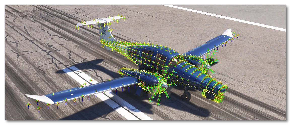
The parameters available in this section are as follows:
| Parameter | Description | Type | Required |
|---|---|---|---|
version | This is the version of this kind of object to use. Available values are:0 - This is the initial version of the fuselage object definition. | Float | Yes |
position | This parameter is used to define the position of the fuselage object relative to the Datum Reference Point of the aircraft. The values are given as (x, y, z) in ft, for example:position = 40, 0, 0The values set here will override those given for the fuselage_center_pos parameter, and if you do not set the position, that parameter will be used be default. | List of Floats | No |
size | This parameter is used to define the size of the fuselage object. The values are given as (width, height, length) in ft, for example:size = 6, 3, 3The default values used for this, depending of the aircraft category are as follows:Airplane: - width (x-axis) - fuselage_diameter - height (y-axis) - fuselage_diameter - length (z-axis) - fuselage_lengthHelicopter: - width (x-axis) - square root of reference_frontal_area, - height (y-axis) - square root of reference_frontal_area, - length (z-axis) - reference_lengthHot Air Balloon: - width (x-axis) - 4.0 - height (y-axis) - 4.0 - length (z-axis) - 4.0 | List of Floats | No |
group | This parameter is used to assign the physics object to one or more groups using a tag-like system. You can create your own groups, or use one of the recommended built-in groups. Group assignment has no impact on performance, but can be used for debugging and also (potentially) in custom tools. Please see here for more information:Note On Physics GroupsThe built in group tags that can be used for this kind of object are: - aircraft - extairframe - airframe - fuselage - pN (where N is the object index) - tip | List of Strings | No |
element_number | With this parameter you define the number of surface element vectors that will be used to define the basic cylinder shape of the fuselage object. The values here are given as (width, height, length), for example:element_number= 6, 6, 10Care should be taken with the values used here, as the greater the number, the more calculations the simulation has to perform, so when too many surface vertices are defined for an object there could be repercussions on performance. In general you should keep these to the minimum necessary to create the approximate shape of the part of the fuselage being defined.NOTE: You cannot have less than 3 elements defined for each axis. | List of Floats | Yes |
dim_scale_top | These parameters are used to modify the shape of the base cylinder, such that it conforms as close as possible to the base shape of the aircraft model. Scaling is done across the top, middle and bottom of the cylinder shape, and is accomplished by supplying pairs of values in a list where the first value is the position (expressed as a Percent Over 100) along the cylinder length, and the second value is the scalar to be applied. For example, the following would be used to create a cone shape:dim_scale_top = 0:0, 0.5:0.5, 1:1dim_scale_lat = 0:0, 0.5:0.5, 1:1dim_scale_bottom = 0:0, 0.5:0.5, 1:1When defining these parameters, you can give any number of paired arguments, but - as with the definition of element_number - care should be taken to not have more than the absolute minimum required to define the approximate shape and maintain optimal performance.Default value is 1:1 for all three parameters, and you can have up to a maximum of 10 entries in the list. | List of paired floats | No |
dim_scale_lat | These parameters are used to modify the shape of the base cylinder, such that it conforms as close as possible to the base shape of the aircraft model. Scaling is done across the top, middle and bottom of the cylinder shape, and is accomplished by supplying pairs of values in a list where the first value is the position (expressed as a Percent Over 100) along the cylinder length, and the second value is the scalar to be applied. For example, the following would be used to create a cone shape:dim_scale_top = 0:0, 0.5:0.5, 1:1dim_scale_lat = 0:0, 0.5:0.5, 1:1dim_scale_bottom = 0:0, 0.5:0.5, 1:1When defining these parameters, you can give any number of paired arguments, but - as with the definition of element_number - care should be taken to not have more than the absolute minimum required to define the approximate shape and maintain optimal performance.Default value is 1:1 for all three parameters, and you can have up to a maximum of 10 entries in the list. | List of paired floats | No |
dim_scale_bottom | These parameters are used to modify the shape of the base cylinder, such that it conforms as close as possible to the base shape of the aircraft model. Scaling is done across the top, middle and bottom of the cylinder shape, and is accomplished by supplying pairs of values in a list where the first value is the position (expressed as a Percent Over 100) along the cylinder length, and the second value is the scalar to be applied. For example, the following would be used to create a cone shape:dim_scale_top = 0:0, 0.5:0.5, 1:1dim_scale_lat = 0:0, 0.5:0.5, 1:1dim_scale_bottom = 0:0, 0.5:0.5, 1:1When defining these parameters, you can give any number of paired arguments, but - as with the definition of element_number - care should be taken to not have more than the absolute minimum required to define the approximate shape and maintain optimal performance.Default value is 1:1 for all three parameters, and you can have up to a maximum of 10 entries in the list. | List of paired floats | No |
dim_offset_middle | This parameter is used to modify the position of the center-line of the base cylinder form along the Z-axis, permitting the creation of curves up or down to suit specific aircraft shapes. For example:dim_offset_middle = 0:0, 0.5:2, 1:-1The setup above would deform the cylinder in the following way:Default value is 1:0, and you can have up to a maximum of 10 entries in the list.. | List of paired floats | No |
surface_cx | This defines the drag coefficient for the surface of the fuselage object when moving through airflow hitting the surface at close to a tangent. This is a list of 3 unitless values given as (x, y, z) and will be used as part of the surface matrix computations. For example:surface_cx = 1.15, 0.5, 0.16The default values used for this, depending of the aircraft category are as follows:Airplane: - x-axis: fuselage_lateral_cx - y-axis: fuselage_vertical_cx - z-axis: fuselage_longitudinal_cxHelicopter: - x-axis: side_drag_force_cf - y-axis: side_drag_force_cf - z-axis: drag_force_cfHot Air Balloon: - x-axis: 0.4 - y-axis: 0.4 - z-axis: 0.4For more information, please see here: Note On Surface Cx | List of Floats | Yes |
surface_cx_tangent | This defines the surface friction coefficient when the airflow comes at a perfect tangent to the surface of the fuselage object being defined. This is a list of 3 unitless values given as (x, y, z) and will be used as part of the surface matrix computations. For example:surface_cx_tangent = 0.09, 0.01, 0.01For more information, please see here: Note On Surface Cx.Default value for X, Y, and Z is 0.04. | List of Floats | Yes |
surface_cx_normal | This defines the the drag coefficient for surface calculations when you have an AoA of 90°. This is a list of 3 unitless values given as (x, y, z) and will be used as part of the surface matrix computations. For example:surface_cx_normal = 1.15, 0.5, 0.16For more information, please see here: Note On Surface Cx. The default values used for this, depending of the aircraft category are as follows:Airplane: - x-axis: fuselage_lateral_cx - y-axis: fuselage_detached_cx - z-axis: fuselage_longitudinal_cxHelicopter: - x-axis: 0.4 - y-axis: 0.4 - z-axis: drag_force_cfHot Air Balloon: - x-axis: 0.4 - y-axis: 0.4 - z-axis: 0.4 | List of Floats | Yes |
surface_cx_efficiency | This defines the the induced drag for surface calculations. This is a list of 3 unitless values given as (x, y, z) and will be used as part of the surface matrix computations. For example:surface_cx_efficiency = 0.2, 0.2, 0.2For more information, please see here: Note On Surface Cx. The default values used for this, depending of the aircraft category are as follows:Airplane: - Default X value is the value given by fuselage_orthogonal_drag_efficiency_cx. - Default Y value is the value given by fuselage_orthogonal_drag_efficiency_cx. - Default Z value is the value given by fuselage_longitudinal_drag_efficiency_cx.Helicopter: - Default value for X, Y, and Z is 0.2.Hot Air Balloon: - Default value for X, Y, and Z is 1.0. | List of Floats | Yes |
surface_cx_nscaler | This defines the unitless scalars (multipliers) that will be applied to the (x, y, z) values in the surface matrix. For example:surface_cx_nscaler = 4, 4, 4For more information, please see here: Note On Surface CxDefault values are 1, 1, 1. | List of Floats | Yes |
surface_cx_npower | This defines the unitless powers that will be applied to the (x, y, z) values in the surface matrix. For example:surface_cx_npower = 1, 1, 1For more information, please see here: Note On Surface CxDefault values are 1, 1, 1. | List of Floats | Yes |
[OBJ_EA1_SURFACE.N]
This section is used to define a surface object that takes advantage of all the changes in the flight model physics made for Microsoft Flight Simulator 2024. Surface objects are essentially planar boxes that can be positioned, moved and even animated to simulate things like spoilers, ailerons, struts, fins, etc… You can add multiple [OBJ_EA1_SURFACE.N] sections, where N starts at 0 and is incremented by 1 for each new section you add, up to a maximum of 99 (100 objects, total). When working with this section, it is a good idea to enable the Sim Forces debug option, so that you can see the the actual surface description represented in the simulation, shown by the various points used to define the surface vertices (see [OBJ_EA1_FUSELAGE.N] for an example).
The parameters available in this section are as follows:
| Parameter | Description | Type | Required |
|---|---|---|---|
version | This is the version of this kind of object to use. Available values are: - 0: This is the initial version of the surface object, which has an issue with incorrect surface_cx_tangent.z values. - > 0: Any value greater than 0 fixes the issue with surface_cx_tangent.z, and also allows use of the parameter modifier_local_angle_scalar. | Float | Yes |
position | This parameter is used to define the position of the surface object relative to the Datum Reference Point of the aircraft. The values are given as (x, y, z) in ft, for example:position = 40, 0, 0If you do not set the position, that parameter will default to 0, 0, 0. | List of Floats | No |
size | This parameter is used to define the size of the surface object. The values are given as (width, height, length) in ft. For example:size = 6, 3, 3Default values for width, height, and length are: 1, 1, 1 | List of Floats | No |
group | This parameter is used to assign the physics object to one or more groups using a tag-like system. You can create your own groups, or use one of the recommended built-in groups. Group assignment has no impact on performance, but can be used for debugging and also (potentially) in custom tools. Please see here for more information:Note On Physics GroupsThe built in group tags that can be used for this kind of object are:pN (where N is the object index)surface | List of Strings | No |
element_number | With this parameter you define the number of surface element vectors that will be used to define the basic planar shape of the surface object. The values here are given as (width, height, length), for example:element_number= 6, 6, 10Care should be taken with the values used here, as the greater the number, the more calculations the simulation has to perform, so when too many surface vertices are defined for an object there could be repercussions on performance. In general you should keep these to the minimum necessary to create the approximate shape of the surface being defined.The default values used for this parameter are: 1, 1, 1 | List of Floats | No |
surface_angle | This defines the initial angle of the surface along each of the three axis, X, Y, Z, expressed in degrees, before any modifiers have been applied. For example:surface_angle = 0, 90, 0Note that you may offset the point of rotation from the center of the surface using the surface_relative_position parameter.Default value for X, Y and Z is 0. | List of Floats | No |
surface_relative_position | This allows you to define the center of rotation for the surface_angle settings or the applied modifier, and is only used when either of those parameters are included in the surface definition (if they are not included then this will do nothing). It should be used on those occasions where you want to position the surface at a specific location, but rotate it around an axis other than the location point. For example:surface_relative_position = 0, 5, 3.2Default value for X, Y and Z is 0. | List of Floats | No |
surface_cx | This defines the drag coefficient for the surface when moving through airflow hitting the surface at close to a tangent. This is a list of 3 unitless values given as (x, y, z) and will be used as part of the surface matrix computations. For example:surface_cx = 1.15, 0.5, 0.16For more information, please see here: Note On Surface CxDefault value for X, Y and Z is 1. | List of Floats | No |
surface_cx_tangent | This defines the surface friction coefficient when the airflow comes at a perfect tangent to the surface being defined. This is a list of 3 unitless values given as (x, y, z) and will be used as part of the surface matrix computations. For example:surface_cx_tangent = 0.09, 0.01, 0.01For more information, please see here: Note On Surface CxDefault value for X, Y, and Z is 0.04. | List of Floats | No |
surface_cx_normal | This defines the the drag coefficient for surface calculations when you have an AoA of 90°. This is a list of 3 unitless values given as (x, y, z) and will be used as part of the surface matrix computations. For example:surface_cx_normal = 1.15, 0.5, 0.16For more information, please see here: Note On Surface CxDefault value for X, Y, and Z is 0.4. | List of Floats | No |
surface_cx_efficiency | This defines the the induced drag for surface calculations. This is a list of 3 unitless values given as (x, y, z) and will be used as part of the surface matrix computations. For example:surface_cx_efficiency = 0.2, 0.2, 0.2For more information, please see here: Note On Surface CxDefault value for X, Y, and Z is 0.2. | List of Floats | No |
surface_cx_nscaler | This defines the unitless scalars (multipliers) that will be applied to the (x, y, z) values in the surface matrix. For example:surface_cx_nscaler = 4, 4, 4For more information, please see here: Note On Surface CxDefault values are 1, 1, 1. | List of Floats | No |
surface_cx_npower | This defines the unitless powers that will be applied to the (x, y, z) values in the surface matrix. For example:surface_cx_npower = 1, 1, 1For more information, please see here: Note On Surface CxDefault values are 1, 1, 1. | List of Floats | No |
modifier.n | This parameter is used to define one or more modifiers for the surface being created to use as a base control for any animation and movement. Each modifier has an index, starting from n=0, up to a maximum of n=9, and they can work on one or more of the following areas: - the position of the surface (position) - the angle of the surface (surface_angle) - the position of the rotation pivot point (surface_relative_position)The reason this is an indexed parameter is because you can have multiple modifiers on the same surface such that - for example - the surface will move with the elevator and the rudder:modifier.0 = elevator_anglemodifier.1 = rudder_angleBy default this value is “”, meaning no modifier is active and no animation will occur. | String:left_aileron_angleright_aileron_angleelevator_anglerudder_anglespoiler_angleleft_flap_angleright_flap_anglegear_position | No |
modifier_angle_scalar.n | This defines the scalar that will be applied to the angle of the surface - as defined by the surface_angle parameter - when it has a modifier applied to it and is animated in the simulation. This parameter is indexed, where the index used must match a modifier index.Using this parameter permits you to change the angle of rotation around the three axis so it “fits” the animated element of the aircraft being simulated.Note that values are relative to the aircraft axis, but if you need local axis you can use the modifier_local_angle_scalar.n parameter (which requires that the surface version is >0).Default values are 1, 1, 1 (X-axis, Y-axis, Z-axis) | List of Floats | No |
modifier_local_angle_scalar.n | This defines the scalar that will be applied to the angle of the surface - as defined by the surface_angle parameter - when it has a modifier applied to it and is animated in the simulation. This parameter is indexed, where the index used must match a modifier index.Using this parameter permits you to change the angle of rotation around the three axis so it “fits” the animated element of the aircraft being simulated.Note that values are relative to the local surface axis, but if you need aircraft axis you can use the modifier_angle_scalar.n parameter.Default values are 1, 1, 1 (X-axis, Y-axis, Z-axis)IMPORTANT! This parameter is only available when the surface version is > 0. | List of Floats | No |
modifier_position_scalar.n | This defines the scalar that will be applied to the position of the surface when it has a modifier applied to it and is animated in the simulation. This parameter is indexed, where the index used must match a modifier index.Using this parameter permits you to modify the movement over the three axis so it “fits” the animated element of the aircraft being simulated.Default values are 1, 1, 1(X-axis, Y-axis, Z-axis) | List of Floats | No |
modifier_surface_relative_position_scalar.n | This defines the scalar that will be applied to the position of the rotation pivot point, as defined by the surface_relative_position parameter, when it has a modifier applied to it and is animated in the simulation. This parameter is indexed, where the index used must match a modifier index.Using this parameter permits you to modify the movement over the three axis so it “fits” the animated element of the aircraft being simulated.Default values are 1, 1, 1 (X-axis, Y-axis, Z-axis) | List of Floats | No |
[OBJ_EA1_BALLOON.N]
COMING SOON!
[OBJ_EA1_ANCHORROPE.N]
This is used to define a physics object that is used as an anchor rope for either balloons or airships. You can have multiple of these sections where the appended number N corresponds to its unique ID (starting at 0, and incrementing by 1 for each anchor rope that you wish to add).
The parameters available in this section are as follows:
| Parameter | Description | Type | Required |
|---|---|---|---|
version | This is the version of this kind of object to use. Available values are:0 - This is the initial version of the anchor rope object definition. | Float | Yes |
position | This is the position of the anchor rope object relative to the Datum Reference Point, expressed as X, Y, Z values, in ft. This is the point where the rope will be attached to the protective cover object. | List of Floats | Yes |
size | This is used to define the maximum length of the anchor rope. The length is expressed in meters, and only requires that the first of the three values is defined, the other two should be set to 0, for example:size = 2.0, 0, 0 | List of Floats | Yes |
[OBJ_EA1_PITOTFLAG.N]
This is used to define a physics object that is used to display the “Remove Before Flight” warning hanging from many of the preflight check items. You can have multiple of these sections where the appended number N corresponds to its unique ID (starting at 0, and incrementing by 1 for each flag that you wish to add). Full instructions on setting up this item are given on the following page:
The parameters available in this section are as follows:
| Parameter | Description | Type | Required |
|---|---|---|---|
version | This is the version of this kind of object to use. Available values are:0 - This is the initial version of the pitot flag object definition. | Float | Yes |
position | This is the position of the object relative to the Datum Reference Point, expressed as X, Y, Z values, in ft. This is the point where the flag will be attached to the protective cover object. | List of Floats | Yes |
size | This is used to define the size of the flag that will display the warning text. The size is expressed in meters as width, length, thickness. Note that thickness should be 0 and is not used by this object, for example:size = 0.75, 0.2, 0 | List of Floats | Yes |
linked_behavior_index | This defines the interaction that is to be used for the flag. Since the flag can be attached to various different protective covers, you need to specify the behavior to use when the cover is removed so that it matches the cover type. | Enum:1: Engine Cover2: Pitot Cover3: Static Cover5: Gear Pin6: Propeller Cover or Rotor Cover | Yes |
surface_relative_position.N | The warning flag object is created with physical properties which means that it will move around based on the wind and airflow around the aircraft. To prevent the object “clipping” into anything it shouldn’t this parameter is used to set the relative position of one or more collision surfaces, where the surface index N starts at 0 and can go up to 9 (so up to 10 collision surfaces in total).This surface plane position is relative to the position of the flag, expressed as X, Y, Z offsets, in ft. For example, you may have this flag on a static cover on the aircraft fuselage, and since it should not pass through the airframe model, you would set the position of a collision surface to be where the fuselage is:surface_relative_position.0 = -1, 0, 5Note that for every surface_relative_position.N that is defined, you should have a corresponding surface_angle.N definition. | List of Floats | Yes |
surface_angle.N | This sets the angle of up to 10 collision surfaces at the position defined by the surface_relative_position.N. There should be one angle index N (starting at 0) for every surface_relative_position.N definition. The angle is expressed as three values (in degrees): pitch, bank, and heading. For example:surface_angle.0 = 0, 90, 0 | List of Floats | Yes |
material_guid | Here you give the unique GUID of the material to use for the warning flag. For consistency, we recommend that you use the default Microsoft Flight Simulator 2024 material which has the following GUID:E48F59B9-94E0-4CA2-B261-8E5FFFF3CB03 | String | Yes |
[OBJ_EA1_YAWSTRING.N]
This is used to define a physics object that is used to display the yaw string present on many aircraft. You can have multiple of these sections where the appended number N corresponds to its unique ID (starting at 0, and incrementing by 1 for each yaw string that you wish to add).
The parameters available in this section are as follows:
| Parameter | Description | Type | Required |
|---|---|---|---|
version | This is the version of this kind of object to use. Available values are:0 - This is the initial version of the yawstring object definition. | Float | Yes |
position | This is the position of the object relative to the Datum Reference Point, expressed as X, Y, Z values, in ft. This is the point where the flag will be attached to the protective cover object. | List of Floats | Yes |
element_number | With this parameter you define the number of surface element vectors that will be used to define the basic planar shape of the yaw string object. The parameter requires 3 values but only the first value is used and is what defines the number of physics elements along the length of the string, for example:element_number= 12, 0, 0 | List of Floats | Yes |
element_weight | This defines the weight (in kg) for each element of the yaw string object.Default value is 0.00005. | Float | No |
element_spacing | This defines the spacing between each element of the yaw string object, in meters.Default value is 0.01. | Float | No |
element_width | This defines the width of each element of the yaw string object, in meters.Default value is 0.01. | Float | No |
surface_relative_position.N | The yaw string object is created with physical properties which means that it will move around based on the wind and airflow around the aircraft. To prevent the object “clipping” into anything it shouldn’t this parameter is used to set the relative position of one or more collision surfaces, where the surface index N starts at 0 and can go up to 9 (so up to 10 collision surfaces in total).This collision surface position is relative to the position of the yaw string, expressed as X, Y, Z offsets, in ft. For example, you may have this on the aircraft windshield, and since it should not pass through the windshield model, you would set the position of a collision surface to be where the windshield is:surface_relative_position.0 = -1, 0, 5Note that for every surface_relative_position.N that is defined, you should have a corresponding surface_angle.N definition. | List of Floats | Yes |
surface_angle.N | This sets the angle of up to 10 collision surfaces at the position defined by the surface_relative_position.N. There should be one angle index N (starting at 0) for every surface_relative_position.N definition. The angle is expressed as three values (in degrees): pitch, bank, and heading. For example:surface_angle.0 = 0, 90, 0 | List of Floats | Yes |
[OBJ_EA1_BANNER.N]
COMING SOON!
[OBJ_AIRGEO_FUSELAGE.N]
This section is used to define a fuselage object that uses the legacy Microsoft Flight Simulator 2020 flight model fuselage definition, which is essentially a box shaped object with an elongated tale section. This model was used by default in previous versions of the simulation to model the aircraft geometry, and its properties are governed by the parameters setup in the [AIRPLANE_GEOMETRY] and [AERODYNAMICS] sections. By default one of these objects is created for the aircraft fuselage but if you set the enable_aircraft_geometry_fuselage parameter to 0, the “base” object will be disabled.
You can add multiple [OBJ_EA1_FUSELAGE.N] sections, where N starts at 0 and is incremented by 1 for each new section you add, up to a maximum of 19 (20 objects, total).
[OBJ_EA1_FUSELAGE.N] objects, which are part of the updated Microsoft Flight Simulator 2024 flight model.When working with this section, it is a good idea to enable the Sim Forces debug option, so that you can see the the actual surface description represented in the simulation, shown by the various points used to define the surface vertices (see [OBJ_EA1_FUSELAGE.N] for an example).
The parameters available in this section are as follows:
| Parameter | Description | Type | Required |
|---|---|---|---|
position | This parameter is used to define the position of the fuselage object relative to the Datum Reference Point of the aircraft. The values are given as (x, y, z) in ft, for example:position = 40, 0, 0The values set here will override those given for the fuselage_center_pos parameter, and if you do not set the position, that parameter will be used be default. | List of Floats | No |
size | This parameter is used to define the size of the fuselage object. The values are given as (width, height, length) in ft, for example:size = 6, 3, 3The default values used for this are as follows:width (x-axis) - fuselage_diameterheight (y-axis) - fuselage_diameterlength (z-axis) - fuselage_length | List of Floats | No |
group | This parameter is used to assign the physics object to one or more groups using a tag-like system. You can create your own groups, or use one of the recommended built-in groups. Group assignment has no impact on performance, but can be used for debugging and also (potentially) in custom tools. Please see here for more information:Note On Physics GroupsThe built in group tags that can be used for this kind of object are: - aircraft - extairframe - airframe - fuselage - pN (where N is the object index) - tip | List of Floats | No |
[OBJ_AIRGEO_VTAIL.N]
This section is used to define a V-Tail (vertical tail) object for an aircraft. In previous versions of the simulation you could only model the aircraft geometry of a single vertical tail with the parameters available in the [AIRPLANE_GEOMETRY] and [AERODYNAMICS] sections. However, the [OBJ_AIRGEO_VTAIL.N] object available in the current version of the simulation removes the limitation of a single tail and permits the definition of multiple vertical tail objects, which can all have different properties if required.
With the [OBJ_AIRGEO_VTAIL.N] section, you can add one or more additional vertical tale objects where N starts at 0 and is incremented by 1 for each new section you add, up to a maximum of 9 (10 objects, total). If you do not want to add vertical tails to the default tail created by the simulation, then you should set the enable_aircraft_geometry_vtail parameter to 0, which will disable the default object and either let you have no vertical tail, or add in one or more custom v-tail objects.
The parameters available in this section are as follows:
| Parameter | Description | Type | Required |
|---|---|---|---|
position | This parameter is used to define the position of the v-tail object relative to the Datum Reference Point of the aircraft. The values are given as (x, y, z) in ft, for example:position = 0, 0.64, -12.5If the parameter is omitted they will default to:x-axis -0y-axis - vtail_pos_vertz-axis - vtail_pos_lon | List of Floats | No |
area | The vertical base-to-tip area of the static part of the vertical tail, in sqft. This area will impact the yaw moment caused by the vertical stabilizer.Default value is vtail_area. | Float | No |
span | This is the vertical distance from the vertical tail-fuselage intersection to the tip of the vertical tail, in ft. A large vtail span will impact the roll moment of the propeller wash but also resist the aircraft roll movement. It will also counter adverse yaw and counter induced roll during rudder inputs.Default value is vtail_span. | Float | No |
sweep | This is the angle the vertical tail leading edge makes with a vertical line perpendicular to the fuselage, as seen when looking at the side of the vertical tail (in degrees).Default value is vtail_sweep. | Float | No |
dihedral | This is the angle between the tail section and the Y-axis in the Y-Z plane. The tail dihedral angle contributes to the aircraft lateral stability and control, aircraft performance, and the tail aerodynamic efficiency, and is often the same as the sweep angle.Default value is 0. | Float | No |
incidence | This is the angle between the fuselage center line (Y-axis) and the v-tail chord line at the root.Default value is 0. | Float | No |
group | This parameter is used to assign the physics object to one or more groups using a tag-like system. You can create your own groups, or use one of the recommended built-in groups. Group assignment has no impact on performance, but can be used for debugging and also (potentially) in custom tools. Please see here for more information:Note On Physics GroupsThe built in group tags that can be used for this kind of object are: - aircraft - extairframe - airframe - hstab - elevator - htail - pN (where N is the object index) | List of Strings | No |
[OBJ_AIRGEO_HTAIL.N]
This section is used to define an H-Tail (horizontal tail) object for an aircraft. In previous versions of the simulation you could only model the aircraft geometry of a single horizontal tail with the parameters available in the [AIRPLANE_GEOMETRY] and [AERODYNAMICS] sections. However, the [OBJ_AIRGEO_HTAIL.N] object available in the current version of the simulation removes the limitation of a single tail and permits the definition of multiple vertical tail objects, which can all have different properties if required.
With the [OBJ_AIRGEO_HTAIL.N] section, you can add one or more additional horizontal tale objects where N starts at 0 and is incremented by 1 for each new section you add, up to a maximum of 9 (10 objects, total). If you do not want to add horizontal tails to the default tail created by the simulation, then you should set the enable_aircraft_geometry_htail parameter to 0, which will disable the default object and either let you have no horizontal tail, or add in one or more custom h-tail objects.
The parameters available in this section are as follows:
| Parameter | Description | Type | Required |
|---|---|---|---|
position | This parameter is used to define the position of the h-tail object relative to the Datum Reference Point of the aircraft. The values are given as (x, y, z) in ft, for example:position = 0, 0.64, -12.5If the parameter is omitted they will default to:x-axis - 0y-axis - htail_pos_vertz-axis - htail_pos_lon | List of Floats | No |
area | Area of the static part of the horizontal tail, in sqft. This area will impact the pitch moment caused by the horizontal tail.Default value is htail_area. | Float | No |
span | This is the horizontal distance between the tips of the horizontal tail object, in ft.Default value is htail_span. | Float | No |
sweep | This is the angle the horizontal tail leading edge makes with a horizontal line perpendicular to the fuselage, as seen when looking down at the top of the horizontal tail (in degrees).Default value is htail_sweep. | Float | No |
dihedral | This is the angle between the tail section and the Y-axis in the Y-Z plane. The tail dihedral angle contributes to the aircraft lateral stability and control, aircraft performance, and the tail aerodynamic efficiency, and is often the same as the sweep angle.Default value is 0. | Float | No |
incidence | This defines the angle of rotation around the X-axis (lateral axis) of the h-tail object.Default value is htail_incidence. | Float | No |
group | This parameter is used to assign the physics object to one or more groups using a tag-like system. You can create your own groups, or use one of the recommended built-in groups. Group assignment has no impact on performance, but can be used for debugging and also (potentially) in custom tools. Please see here for more information:Note On Physics GroupsThe built in group tags that can be used for this kind of object are: - aircraft - extairframe - airframe - vstab - rudder - vtail - pN (where N is the object index) | List of Strings | No |
[OBJ_AIRGEO_WING.N]
This section is used to define a wing object for an aircraft. In previous versions of the simulation you could only model the aircraft geometry of a single pair of wings with the parameters available in the [AIRPLANE_GEOMETRY] and [AERODYNAMICS] sections. However, the [OBJ_AIRGEO_WING.N] object available in the current version of the simulation removes the limitation of a single pair of wings and permits the definition of multiple wing objects, which can all have different properties if required.
With the [OBJ_AIRGEO_WING.N] section, you can add one or more additional wing objects where N starts at 0 and is incremented by 1 for each new section you add, up to a maximum of 9 (10 objects, total). If you do not want to add wings to the default wings created by the simulation, then you should set the enable_aircraft_geometry_wing parameter to 0, which will disable the default object and either let you have no wing objects, or add in one or more custom wing objects.
The parameters available in this section are as follows:
| Parameter | Description | Type | Required |
|---|---|---|---|
position | This parameter is used to define the position of the wing object relative to the Datum Reference Point of the aircraft. The values are given as (x, y, z) in ft, for example:position = 0, 0.64, -12.5If the parameter is omitted they will default to:x-axis -0y-axis - wing_pos_apex_vertz-axis - aero_center_lift | List of Floats | No |
area | Total area of the top surface of the wing from tip-to-tip, in sqft. The wing area impacts the target lift and drag forces. For example it directly impacts lift proportionally to the area: \(L = 0.5 \times p \times v \times v \times WingArea \times C_L\)Default value is wing_area. | Float | No |
span | The horizontal distance between the wing tips, in ft. The wing span impacts the distribution of the forces over the aircraft, and the larger the wing span the greater the increase in the roll and yaw moment of ailerons and also the resistance to the roll movement of the aircraft.Default value is wing_span. | Float | No |
sweep | This is the angle the leading edge of the wing makes with the fuselage, as seen when looking down on top of an aircraft (expressed in degrees).Default value is wing_sweep. | Float | No |
incidence | This is the angle (in degrees) that the mean wing Chord makes with a horizontal line parallel to the ground, as seen when looking at the side of an aircraft from the wing tip. Note that if you have the Sim Forces debug on, changes in the incidence angle will only affect the orientation of surface elements without changing their positioning or the overall wing shape (essentially “rotating” the surface elements around themselves, while the wing plane remains unchanged).Default value is wing_incidence. | Float | No |
dihedral | This is the angle between the wing leading edge and a horizontal line parallel to the ground, as seen when looking at the front of an aircraft. Technically defined as the dihedral angle Lambda, in degrees. The wing dihedral impacts secondary effects such as induced roll and adverse yaw.Default value is wing_dihedral. | Float | No |
twist | This is the difference in wing incidence from the root Chord and the tip Chord of the wing (in degrees). Technically defined as the wing twist epsilon. Note that if you have the Sim Forces debug on, changes in the twist angle will only affect the orientation of surface elements without changing their positioning or the overall wing shape (essentially “rotating” the surface elements around themselves, while the wing plane remains unchanged).Default value is wing_twist. | Float | No |
stallalpha | This defines the theoretical average alpha (AoA) at which the wing will stall, in degrees.Default value is stallalpha. | Float | No |
stallalpha_ff | This defines the theoretical average alpha (AoA) at which the wing will stall in full-flap configuration, in degrees.Default value is stallalpha_ff. | Float | No |
group | This parameter is used to assign the physics object to one or more groups using a tag-like system. You can create your own groups, or use one of the recommended built-in groups. Group assignment has no impact on performance, but can be used for debugging and also (potentially) in custom tools. Please see here for more information:Note On Physics GroupsThe built in group tags that can be used for this kind of object are: - aircraft - extairframe - airframe - wing - left - right - inner - outer - root - tip - middle - up - pN (where N is the object index) | List of Strings | No |
[AIRSHIP_SYSTEM]
This section is only for airships and is used to setup the different components related to the gas compartments and envelope.
The available parameters are:
| Parameter | Description | Type | Required |
|---|---|---|---|
envelope_volume | This gives the total volume of the airship envelope, in cubic meters. This volume is constant, and the airship system’s primary function is to maintain the shape and integrity of the envelope. This value will be used to calculate the buoyancy force for the airship. | Float | Yes |
envelope_center | Here you give the offset from the Datum Reference Point that defines the center of buoyancy for the airship. This offset is expressed as three values - in meters - of the format “x, y, z”, for example:envelope_center = 0, 0, -2.5 | List of Floats | Yes |
default_overpressure | This is the nominal pressure of the inside of the envelope relative to ambient pressure at take-off, given in inches of water (inWG). | Float | Yes |
gas_compartment.N | This parameter defines the different gas compartments that your airship has, where the appended number N corresponds to the unique ID for each compartment (starting at 1, and incrementing by 1 for each compartment that you wish to add).The envelope of an airship is usually divided into several areas containing different gases. For example, most semi-rigid airships have a large main helium compartment and two air ballonets that can be used as “air ballast”. The helium content should remain constant during flight, while the ballonets will inflate or deflate in order to maintain a safe pressure inside the envelope.This parameter requires a hash map with the following format:gas_compartment.1 = name:<name> #gas_type:<enum> #gas_molar_mass:<value> #max_volume:<cubic_m> #default_volume:<cubic_m> #center:<xyz_list> #damper_max_flow:<cubic_m>Please see the table given in the Gas Compartment Map section for the full contents of this hash map. | Hash Map | Yes |
valve.N | This parameter defines the properties of an outflow valve, where the appended number N corresponds to the unique ID for each valve (starting at 1, and incrementing by 1 for each valve that you wish to add).In general there will be at least one valve for each gas compartment, and these are used in order to prevent excessive pressure inside the envelope.This parameter requires a hash map with the following format:gas_compartment.1 = name:<name> #gas_compartment:<index> #pressure_setting:<inWG>Please see the table given in the Valve Map section for the full contents of this hash map. | Hash Map | Yes |
Gas Compartment Map
The table below gives the keys and expected values that should be used when defining the gas_compartment.N hash map.
| Key | Value | Description | Required |
|---|---|---|---|
Name | String | This is a name string that is used as an alias to identify the gas compartment. It will also be used as the reference index for SimVars, and note that the name is the only guaranteed reference to the component due to the fact that the Modular Aircraft Merging process may change the index. The name cannot contain special characters or spaces. | Yes |
gas_type | Enum | This defines the gas type that the compartment will be filled with. Possible values are as follows: - air - helium / He - hydrogen / H2 - otherNote that if the value is “other” then you must also include the gas_molar_mass value. | Yes |
gas_molar_mass | Float | This defines the molar mass of the gas. This key is only required when the gas_type is set to “other”, and the value should be the mass expressed as kg/mol. | No |
max_volume | Float | This is the maximum volume of gas that the compartment can take, expressed in cubic meters. If not included then it will default to the total volume of the envelope, as defined by the envelope_volume parameter. | No |
default_volume | Float | This is the gas volume that the compartment should have when the flight starts, expressed in cubic meters. | Yes |
center | List | This defines the center of mass for the compartment. This is expressed as a three value list - x, y, z - which gives an offset in meters from the Datum Reference Point.If not included then this will default to the same set of values given for the the envelope_center parameter. | No |
damper_max_flow | Float | This defines the maximum air intake into the compartment, expressed in cubic meters. This key is only required when the gas_type key is set to “Air”. The key will be ignored for compartments that store any other gas type. | No |
Valve Map
The table below gives the keys and expected values that should be used when defining the valve.N hash map.
| Key | Value | Description | Required |
|---|---|---|---|
Name | String | This is a name string that is used as an alias to identify the valve. It will also be used as the reference index for SimVars, and note that the name is the only guaranteed reference to the component due to the fact that the Modular Aircraft Merging process may change the index. The name cannot contain special characters or spaces. | Yes |
gas_compartment | Integer | This is the index of the gas compartment that the valve should be attached to. | Yes |
pressure_setting | Float | This defines the pressure - relative to ambient pressure - at which the valve will open when in “unlocked” (auto) mode. Note that for helium compartments, the valve will be set to open at a much higher pressure so that the airship doesn’t lose helium unless it is flying above its safe altitude (pressure height). This value is expressed in inches of water (inWG). | Yes |
[INTERACTIVE POINTS]
Interactive Points in Microsoft Flight Simulator 2024 are used to define the position of various doors of the aircraft - regular, emergency, and cargo doors - as well as some other points to interact with Apron Services, such as the end of a fuel hose to interact with a FuelTruck, or the end of an electrical cable to interact with a GroundPowerUnit vehicle. Interactive points should be added through the SimObject Editor, and only tweaked if required through the flight_model.cfg file.
major is set to 1 or higher. If set to less than 1, this section is ignored and the The [INTERACTIVE POINTS] section should contain one or more interactive_point.i = <DATA> definitions, where i is a value between 0 and N - 1. , and <DATA> is a list of values that set up the interactive point. Below you can see an example of interactive points being defined:
[INTERACTIVE POINTS]
interactive_point.0 = Name:pDoorFrontL #Properties: 0.4, 27.93, -6.05, 3.02, 0, 0, 0, -86, 72, 16, 85, 3, -2, 33, -1
interactive_point.1 = Name:pDoorFrontR #Properties: 0.4, 27.93, 6.05, 3.02, 0, 0, 0, 86, 85, 3, 72, 16, -2, 33, -1
interactive_point.2 = Name:pDoorCentreL #Properties: 0.4, -53, -5.2, 3, 0, 0, 0, -103, 0, 0, 0, 0, 0, 0, -1
interactive_point.3 = Name:pDoorCentreR #Properties: 0.4, -53, 5.2, 3, 0, 0, 0, 103, 0, 0, 0, 0, 0, 0, -1
interactive_point.4 = Name:pDoorBackL #Properties: 0.4, -29.5, 2, -1.8, 1, 0, 0, 90, 0, 0, 0, 0, 0, 0, -1
interactive_point.5 = Name:pDoorBackR #Properties: 0.4, 18, 1.93, -1.9, 1, 0, 0, 90, 0, 0, 0, 0, 0, 0, -1
interactive_point.6 = Name:pEmergencyL #Properties: 0.4, -4, -6, 6.2, 2, 0, 0, -90, 0, 0, 0, 0, 0, 0, -1
interactive_point.7 = Name:pEmergencyR #Properties: 0.4, -4, 6, 6.2, 2, 0, 0, 90, 0, 0, 0, 0, 0, 0, -1
interactive_point.8 = Name:pCargo1 #Properties: 0, 36.3, 10.78, -5.18, 4, 0, 0, 45, 0, 0, 0, 0, 0, 0, -1
interactive_point.9 = Name:pCargo2 #Properties: 0, 0, -54.59, -7.57, 3, 0, 0, -90, 0, 0, 0, 0, 0, 0, -1
The available parameters for the [INTERACTIVE POINTS] section are:
| Parameter | Description | Type | Required |
|---|---|---|---|
interactive_point.N | A hash map that defines the name and properties of an interactive point. | Hash Map | No |
Each interactive point definition requires a hash map with the following keys:
| Key | Value | Description | Required |
|---|---|---|---|
Name | String | This is a name string that is used as an alias to identify the interactive point. It will also be used as the reference index for SimVars, and note that the name is the only guaranteed reference to the component due to the fact that the Modular Aircraft Merging process may change the index. The name cannot contain special characters or spaces. | Yes |
Properties | List | List that contains all the information about the interactive point. | Yes |
For the properties, you need to supply a list of 15 different values, and these can be edited directly in the simulation when Live Edition is enabled. The table below explains what each one of the values represents, as well as the Interactive Points SimVar associated with it (if it has one):
| Position | Position Name | Description | Type | SimVar |
|---|---|---|---|---|
| 0 | Open Close Rate | Percent Over 100 per second of animation of the interactive point (used mostly for doors). | Float | - |
| 1 | Pos - Z | Coordinate in ft of the point relative to aircraft Datum Reference Point, on the back-to-front (Z) axis. | Float | INTERACTIVE POINT POSZ |
| 2 | Pos - X | Coordinate in ft of the point relative to aircraft Datum Reference Point, on the left-to-right (X) axis. | Float | INTERACTIVE POINT POSX |
| 3 | Pos - Y | Coordinate in ft of the point relative to aircraft Datum Reference Point, on the bottom-to-top (Y) axis. | Float | INTERACTIVE POINT POSZ |
| 4 | Type | Integer corresponding to an enum, determining the type of the point (see the Type, Position, and Orientation section for more details). | Integer:0 = Main exit1 = Cargo exit/door2 = Emergency exit3 = Fuel hose4 = Ground Power cable5 = Air Start Unit6 = Tailhook7 = Drop Exit (for skydiving)8 = Window99 = Unknown (used for errors) | INTERACTIVE POINT TYPE |
| 5 | Orientation - Pitch | Pitch, in degrees, of the point orientation, where 0° means horizontal. | Float | INTERACTIVE POINT PITCH |
| 6 | Orientation - Bank | Bank, in degrees, of the point orientation (currently unused, please set 0 here). | Float | INTERACTIVE POINT BANK |
| 7 | Orientation - Heading | Heading, in degrees, of the point orientation (0° means same heading as the aircraft). | Float | INTERACTIVE POINT HEADING |
| 8 | Jetway Left Bend | A percentage value for the jetway left bend. See the Jetway Values section for more information. | Float | INTERACTIVE POINT JETWAY LEFT BEND |
| 9 | Jetway Left Deployment | A value, in degrees, for the jetway left deployment. See the Jetway Values section for more information. | Float | INTERACTIVE POINT JETWAY LEFT DEPLOYMENT |
| 10 | Jetway Right Bend | A percentage value for the jetway right bend. See the Jetway Values section for more information. | Float | INTERACTIVE POINT JETWAY RIGHT BEND |
| 11 | Jetway Right Deployment | A value, in degrees, for the jetway right deployment. See the Jetway Values section for more information. | Float | INTERACTIVE POINT JETWAY RIGHT DEPLOYMENT |
| 12 | Jetway Top Horizontal | A value, between -100 and 100, for the jetway horizontal line. See the Jetway Values section for more information. | Float | INTERACTIVE POINT JETWAY TOP HORIZONTAL |
| 13 | Jetway Top Vertical | A value, between -100 and 100, for the jetway vertical line. See the Jetway Values section for more information. | Float | INTERACTIVE POINT JETWAY TOP VERTICAL |
| 14 | Exit Open Failure Speed | A value which corresponds to the speed at which the aircraft will have a failure if an exit is open, in ft per second. This is only valid if the interactive point is of the type 0 (Exit). If set to -1, failures of this type will be disabled, and if not included then the default speed is 50 ft per second | Float | - |
[yaw_string]
This section is for setting up a yaw string on the aircraft. The available parameter is:
| Parameter | Description | Type | Required |
|---|---|---|---|
yaw_string_available | Sets whether the simulation should generate the appropriate values for a yaw-string or not. Enabling this does nothing visually, but enables the SimVars YAW STRING ANGLE and YAW STRING PCT EXTENDED which can then be used to animate a yaw-string model.For yaw-strings in Microsoft Flight Simulator 2024 please see: [OBJ_EA1_YAWSTRING.N] | Boolean | No |
[HELICOPTER]
This section is for setting up the various helicopter-specific components of the flight model. If you are modelling a helicopter then this section is essential, and is used - along with the [FUSELAGE_AERODYNAMICS], [MAINROTOR] and [SECONDARYROTOR] sections - to define the flight model, and including these sections usually means there is no need to include data for the [FLIGHT_TUNING], [AERODYNAMICS] and [AIRPLANE_GEOMETRY] sections. It is worth noting, however, that you will need to set up the [TURBOPROP_ENGINE] and [TURBINEENGINEDATA] sections (those parameters that are not flagged as “jet only”) of the engines.cfg file as well.
The available parameters are:
| Parameter | Description | Type | Required |
|---|---|---|---|
enable_custom_throttles_control | When this parameter is set to 1 (TRUE) you may control the engine throttles directly using the appropriate SimVars, therefor bypassing (essentially disabling) the default internal simulation functionality.Default value is 0 (FALSE). | Bool | No |
reference_length | The overall length of the helicopter fuselage (excluding rotors), in ft. | Float | Yes |
reference_frontal_area | The front facing area of the helicopter fuselage (excluding rotors), in sqft. | Float | Yes |
reference_side_area | The lateral facing area of the helicopter fuselage (excluding rotors), in sqft. | Float | Yes |
lift_aero_center | The longitudinal position, in feet, from the Datum Reference Point of the helicopter that represents the vertical aerodynamic center.Default value is the Z component of the Datum Reference Point. | Float | No |
side_aero_center | The longitudinal position, in feet, from the Datum Reference Point of the helicopter that represents the lateral aerodynamic center.Default value is the Z component of the Datum Reference Point. | Float | No |
right_trim_scalar | This value scales the lateral cyclic trim position.Default value is 1. | Float | No |
front_trim_scalar | This value scales the longitudinal cyclic trim position.Default value is 1. | Float | No |
right_trim_step | The right trim increment value.Default value is 0.005. | Float | No |
front_trim_step | The front trim increment value.Default value is 0.005. | Float | No |
governed_pct_rpm_ref | This is the ratio of the rated RPM that the rotor RPM governor will try to achieve, expressed as a Percent Over 100.Default value is 1. | Float | No |
governed_pct_rpm_min | This is the ratio of the rated RPM above which the governor will be enabled, expressed as a Percent Over 100. Note that this value must be positive and negative values will be clamped at 0.Default value is 0. | Float | No |
governor_speed_limit | This sets the limit on the maximum speed of throttle movement by the governor. The value given here is a a ratio between 0 and 1, where the limit is calculated as ratio / sec. If set to 0, then there is no limit imposed.Default value is 1. | Float | No |
rotor_brake_scalar | With this parameter you can scale the rotor braking torque.IMPORTANT! If your helicopter does not have a rotor brake, this must be set to 0, otherwise users may have issues if the helicopter is used in career missions.Default value is 1. | Float | No |
rotor_brake_torque | This value adjusts the rotor braking torque. The value is in ftlbs per ft.IMPORTANT! If your helicopter does not have a rotor brake, this must be set to 0, otherwise users may have issues if the helicopter is used in career missions.Default value is 600. | Float | No |
rotor_brake_bleed_rate | This defines the decay per second (as a Percent Over 100) of the brake type. Value must be be greater or equal to 0Default value is 0.5. | Float | No |
rotor_friction_torque | This value adjusts the speed at which the rotors will slow down after shutting off the engine. The value is in ftlbs per ft.Default value is 0. | Float | No |
rotor_node.n | This parameter is used to give the nodes for the center of each rotor, where n increments by 1 for each engine with a node. This will be used to generate the blurring effect when the rotor is spinning. For example:rotor_node.0 = Nodes:rotor_Lrotor_node.1 = Nodes:rotor_RIt is also possible to configure more than one node per engine (this allows to have 2 versions of a rotor with low or high detail), for example:rotor_node.0 = Nodes:rotor_L, rotor_L_blurrotor_node.1 = Nodes:rotor_R, rotor_R_blurIf the node is not part of the base model in a modular SimObject, then you can also supply an alias which is used in the merge process to ensure the correct node is selected, for example:rotor_node.0 = SimAttachmentAlias:Exterior # Nodes:rotor_Lrotor_node.1 = SimAttachmentAlias:Exterior # Nodes:rotor_R | Hash Map | No |
torque_scalar | With this parameter you can scale the rotor torque effect.NOTE: This parameter will only be used when the use_modern_surfaces parameter is set to 0.Default value is 1. | Float | No |
tail_rotor_translating_scalar | This parameter scales the tail rotor thrust.NOTE: This parameter will only be used when the use_modern_surfaces parameter is set to 0.Default value is 1. | Float | No |
disk_roll_animation_scalar | This parameter scales the rotor disk roll animation angle.Default value is 1. | Float | No |
disk_pitch_animation_scalar | This parameter scales the rotor disk pitch animation angle.Default value is 1. | Float | No |
cyclic_roll_control_scalar | This parameter scales the roll cyclic controls. Note that this will be applied to both the positive and negative input, unless cyclic_roll_control_scalar_negative is defined.Default value is 1. | Float | No |
cyclic_roll_control_scalar_negative | This parameter scales the roll cyclic controls.Default value is 1. | Float | No |
cyclic_pitch_control_scalar | This parameter scales the pitch cyclic controls. Note that this will be applied to both the positive and negative input, unless cyclic_pitch_control_scalar_negative is defined.Default value is 1. | Float | No |
cyclic_pitch_control_scalar_negative | This parameter scales the pitch cyclic controls.Default value is 1. | Float | No |
pedal_control_scalar | This parameter scales the pedal controls. This is a legacy parameter, and should only be used when use_modern_surfaces is set to 0 (FALSE).Default value is 1. | Float | No |
pedal_yaw_control_scalar | This parameter scales the pedal controls. This should only be used when use_modern_surfaces is set to 1 (TRUE).NOTE: This parameter can be used on legacy aircraft as well, but it will be cummulative with pedal_control_scalar, and so you should only use one or the other.Default value is 1. | Float | No |
collective_increment | The size of the increments for the collective when using the COLLECTIVE_INCR and COLLECTIVE_DECR events. Value should be between 0 and 1.Defaults value is 0.05. | Float | No |
collective_on_rotor_torque_scalar | This parameter scales the collective impact on rotor torque.NOTE: This parameter will only be used when the use_modern_surfaces parameter is set to 0.Default value is 1. | Float | No |
collective_to_throttle_correlator | Defines the ratio - from 0 to 1 - with which the collective lever control position is added to the twist grip throttle control position. This will then be applied to the engine(s). The actual equation looks like this:throttle = throttle_control + collective_control * collective_to_throttle_correlatorNote that if the parameter is set to 0 or is omitted (and all other collective-to-throttle parameters are also omitted) then the engine throttle will work as a simple throttle twist grip control.IMPORTANT: If you use this parameter, then you cannot use collective_to_throttle_correlator_1d or collective_to_throttle_correlator_2d. | Float | No |
collective_to_throttle_correlator_1d | This defines the relationship between the collective control position and the twist grip throttle. In this case the throttle applied to the engine(s) is calculated as the sum of the twist grip throttle control position and the result of linear interpolation from this table, depending on the collective control position:throttle = throttle_control + f (collective_control)There can be between 2 to 7 pairs of values in this table, and if the dimensions of the table are outside of these bounds, this parameter will be ignored. Values should be between 0 and 1.Note that if the parameter has all values set to 0 or it is omitted (and all other collective-to-throttle parameters are also omitted) then the engine throttle will work as a simple throttle twist grip control.IMPORTANT: If you use this parameter, then you cannot use collective_to_throttle_correlator or collective_to_throttle_correlator_2d. | List of Floats | No |
collective_to_throttle_correlator_2d | This is a 2D table whereThe top row corresponds to the twist grip throttle control position, from 0 to 1The left column corresponds to the collective control position, from 0 to 1All other values correspond to the ratio between these two controls, also from 0 to 1.Together they define the throttle control for *all helicopter engines using a 2D linear interpolation of the given values. This can be used to help maintain nominal rotor RPM when the pilot moves the collective lever. For example:throttle_correlator_table = 0.0 :0.0 :0.5 :1, 0.0 :0.0 :0.18 :0.36, 0.25 :0.0 :0.26 :0.52, 0.5 :0.0 :0.34 :0.68, 0.75 :0.0 :0.42 :0.84,1 :0.0 :0.5 :1 ;This parameter has no default values, but if it is omitted from the CFG file (and all other collective-to-throttle parameters are also omitted), or the size of the table exceeds the maximum permitted size (see the note below) then the engine throttle will work as a simple throttle twist grip control.NOTE: - You can have from 3 to N rows (including the top row with the twist grip throttle values) - You can have from 2 to N columns (including the left column with the collective values). - The combined number of entries (rows * columns) cannot exceed 49. So you could have, for example, 3 rows and 16 columns (48 entries) but not 5 rows and 10 columns (50 entries). | 2D Table of Floats | No |
collective_move_rate_limit | This sets the limit on the maximum speed of movement by the collective. The value given here is a ratio that must be 0 or greater, where the limit is calculated as ratio / sec. If set to 0, then there is no limit imposed, however this will bypass the relationship between the hydraulics system actuators and the collective control.Default value is 1. | Float | No |
collective_move_rate_limit_vr | This sets the limit on the maximum speed of movement by the collective, when the user is in VR mode. The value given here is a ratio that must be 0 or greater, where the limit is calculated as ratio / sec. If set to 0, then there is no limit imposed, however this will bypass the relationship between the hydraulics system actuators and the collective control.Default value is 1. | Float | No |
maxTorquePctLowCollective | This sets the governor of the helicopter to limit the engine throttle in order to keep torque below the value given. The value is expressed as a Percent Over 100.NOTE: This parameter is only used when the helicopter has a turbine engine.Default value is 0. | Float | No |
cyclic_move_rate_limit | Sets the maximum speed of cyclic movement. The value given here is a ratio that must be 0 or greater, where the limit is calculated as ratio / sec. If set to 0, then there is no limit imposed, however this will bypass the relationship between the hydraulics system actuators and the cyclic control.Default value is 1. | Float | No |
rudder_pedals_move_rate_limit | Sets the maximum speed of movement for the rudder pedals. The value given here is a ratio that must be 0 or greater, where the limit is calculated as ratio / sec. If set to 0, then there is no limit imposed, however this will bypass the relationship between the hydraulics system actuators and the rudder control.Default value is 1. | Float | No |
stabilizer_cyclic_scale | If a stabilizer is present and enabled, this is the ratio of assistance it will provide the cyclic.Default value is 0. | Float | No |
stabilizer_rudder_scale | If a stabilizer is present and enabled, this is the ratio of assistance it will provide the rudder.Default value is 0. | Float | No |
engine_internal_moi | This is the internal moment of inertia of the moving parts of one engine for the clutch simulation and the unclutched simulation, in lbs per ft2.Default value is 0.25. | Float | No |
clutch_maximum_torque_up | This is the clutch simulation maximum clutch torque when the engine RPM is pulled up, in lbf * ft.Default value is 1000. | Float | No |
clutch_maximum_torque_down | This is the clutch simulation maximum clutch torque when the engine RPM is pulled down, in lbf * ft.Default value is 1000. | Float | No |
clutch_unclutch_time | The time - in seconds - it takes for the clutch to go from 0% to 100% or from 100% to 0%.Default value is 20. | Float | No |
engine_trim_min | Sets the minimum ratio of the engine rated RPM that can be set by the trimmer. Value is between 0 and 1. Note that this value will be used by the DECREASE_HELO_GOV_BEEP and INCREASE_HELO_GOV_BEEP key events.As an example: if your rated rotor RPM is 1000RPM, setting the min to 0.9 and the max to 1.1 will allow you to set the trimmer to a value between 900RPM and 1100RPM.Default value is 1. | Float | No |
engine_trim_max | Sets the maximum ratio of the engine rated RPM that can be set by the trimmer. Value must be 1 or greater (up to “inifnity”). Note that this value will be used by the DECREASE_HELO_GOV_BEEP and INCREASE_HELO_GOV_BEEP key events.As an example: if your rated rotor RPM is 1000RPM, setting the min to 0.9 and the max to 1.1 will allow you to set the trimmer to a value between 900RPM and 1100RPM.Default value is 1. | Float | No |
engine_trim_rate | Sets the speed of change of the ratio of the engine rated RPM, calculated as RPM Ratio / sec. Note that this value will be used by the DECREASE_HELO_GOV_BEEP and INCREASE_HELO_GOV_BEEP key events.Default value is 0. | Float | No |
assistance_cyclic_pitch_stability_centre | This is used to center the assistance neutral input for the pitch cyclic, in degrees.NOTE: See the Note On Flight Assistance for additional information.Default value is -1.15. | Float | No |
assistance_cyclic_bank_stability_centre | This is used to center the assistance neutral input for the bank cyclic, in degrees.NOTE: See the Note On Flight Assistance for additional information.Default value is -5.7. | Float | No |
assistance_pedal_yaw_stability_centre | This ratio is used to center the assistance neutral input for the pedal.NOTE: See the Note On Flight Assistance for additional information.Default value is 0.15. | Float | No |
assistance_pedal_yaw_rotation | This is the ratio of the yaw rotation velocity countering the proportional force.NOTE: See the Note On Flight Assistance for additional information.Default value is 10. | Float | No |
assistance_pedal_yaw_maxinput | This is the maximum input ratio for all assistance rudder input.NOTE: See the Note On Flight Assistance for additional information.Default value is 0.5. | Float | No |
assistance_pedal_yaw_integralmax | This is the maximum input ratio for the integral part of the assistance rudder input.NOTE: See the Note On Flight Assistance for additional information.Default value is 0.2. | Float | No |
assistance_pedal_yaw_integralspeed | This is the ratio of the yaw rotational velocity countering the integral force.NOTE: See the Note On Flight Assistance for additional information.Default value is 1. | Float | No |
assistance_cyclic_drotation | This is the ratio of the pitch and bank rotational velocity countering the proportional force.NOTE: See the Note On Flight Assistance for additional information.Default value is 0. | Float | No |
assistance_cyclic_pitch_rotation | This is the ratio of the pitch and pitch angle countering the proportional force.NOTE: See the Note On Flight Assistance for additional information.Default value is 2. | Float | No |
assistance_cyclic_bank_rotation | This is the ratio of the pitch and bank angle countering the proportional force.NOTE: See the Note On Flight Assistance for additional information.Default value is 2. | Float | No |
assistance_cyclic_forwardspeed | This is the ratio of the forward speed countering the proportional force.NOTE: See the Note On Flight Assistance for additional information.Default value is 0.01. | Float | No |
assistance_cyclic_sidespeed | This is the ratio of the side speed countering the proportional force.NOTE: See the Note On Flight Assistance for additional information.Default value is 0.01. | Float | No |
assistance_cyclic_integralmax | This parameter defines the maximum stabilization bank or pitch angle integral - in degrees - for horizontal motion, countering the bank angle integral.NOTE: See the Note On Flight Assistance for additional information.Default value is 5. | Float | No |
assistance_cyclic_integralspeed | This is the ratio of the horizontal speed for horizontal motion countering the bank angle integral.NOTE: See the Note On Flight Assistance for additional information.Default value is 0.2. | Float | No |
assistance_cyclic_maxinput | This is the maximum input ratio for all assistance cyclic input.NOTE: See the Note On Flight Assistance for additional information.Default value is 0.15. | Float | No |
assistance_cyclic_maxspeed | This is the maximum speed - in ft per second - for the cyclic assistance. At a speed of 0 ft per second, the assistance works at 100%. At the specified maxspeed, or above, the assistance is disabled, and in between it gradually decreases.NOTE: See the Note On Flight Assistance for additional information.Default value is 100. | Float | No |
assistance_pedal_maxspeed | This is the maximum speed - in ft per second - for the pedal assistance. At a speed of 0 ft per second, the assistance works at 100%. At the specified maxspeed, or above, the assistance is disabled, and in between it gradually decreases.NOTE: See the Note On Flight Assistance for additional information.Default value is 133. | Float | No |
governor_pid | The PID to control the auto throttle governor. The list requires the following 5 inputs: - Proportional factor - Integral factor - Derivative factor - I boundary - D boundaryDefault values are: 0, 0, 0, 0, 0For more information on these PID controller parameters, please see the section on PID Parameters. | List of 5 Floats | No |
vortex_ring_protection_assistance_nominal_planar_airspeed | Nominal value - in Knots - of the true airspeed projection (including ambient wind) onto the helicopter body planar plane (i.e: typically a horizontal speed), below which the vortex ring protection assistance becomes fully active. Must be greater than 0 and less than the vortex_ring_protection_assistance_engage_planar_airspeed value. For more information, please see the Note On Helicopter Vortex Ring Protection Assistance.Default value is 40. | Float | No |
vortex_ring_protection_assistance_engage_planar_airspeed | Threshold value - in Knots - for the true airspeed projection (including ambient wind) onto the helicopter body planar plane (i.e: typically a horizontal speed), below which the vortex ring protection assistance starts to engage. Must be greater than the vortex_ring_protection_assistance_nominal_planar_airspeed value. For more information, please see the Note On Helicopter Vortex Ring Protection Assistance.Default value is 50. | Float | No |
vortex_ring_protection_assistance_vertical_speed_limit | When the vortex ring protection assistance is active, this parameter defines the minimum allowed value - in ft per minute - of the true airspeed projection (including ambient wind) onto the helicopter vertical body axis (i.e: typically a descent rate). Value must be less than 0. For more information, please see the Note On Helicopter Vortex Ring Protection Assistance.Default value is -500. | Float | No |
vortex_ring_protection_assistance_pid | Comma-separated array of PID coefficients for the helicopter vortex ring protection assistance. The list requires the following 3 inputs:Proportional coefficient (Percent Over 100 / ft per second):\(P_{out} = P * (VS_{predicted} - VS_{limit})\)Integral coefficient (Percent Over 100 / ft):\(I_{out} = I_{out\_ previous} + I \times (VS_{predicted} - VS_{limit}) \times dt\)Derivative coefficient (seconds):\(VS_{predicted} = VS + D \times \frac{dVS}{dt}\)To be enabled, at least one of the P or I coefficients must be greater than zero. For more information, please see the Note On Helicopter Vortex Ring Protection Assistance.Default value is 0, 0.06, 1. | List of 3 Floats | No |
Note On Flight Assistance
The different assistance_ parameters are provided to pre-initialise the PID that is used for assistance, and will only be used when flight assistance is enabled. The way the PID works is that it will converge towards a value which makes it possible to stabilize the helicopter in hover, and it’s the assistance_xxxx_xxxx_stability_centre that you can use to pre-initialise the PID. This will make it start directly at the value that stabilizes the helicopter, so it doesn’t “search” as much before stabilizing and is more quickly stable. Note too that there are limits to stabilisation, and if you are too off-center it sometimes does not stabilise at all.
[FUSELAGE_AERODYNAMICS]
This section is for setting up the aerodynamics of a helicopter fuselage.
The available parameters are:
| Parameter | Description | Type | Required |
|---|---|---|---|
use_modern_surfaces | When this is set to 0, it will tell the simulation to use the “legacy” helicopter flight model. However setting this to 1 will select the modern flight model, based on surfaces and CFD calculations.Default value is 0. | Float | No |
drag_force_cf | This is the drag coefficient of the front facing fuselage.Default value is 0. | Float | No |
side_drag_force_cf | This is the drag coefficient of the side facing fuselage.Default value is 0. | Float | No |
pitch_damp_cf | The pitch damping coefficient.NOTE: This parameter will only be used when the use_modern_surfaces parameter is set to 0.Default value is 1. | Float | No |
pitch_stability_cf | The pitch stability coefficient.NOTE: This parameter will only be used when the use_modern_surfaces parameter is set to 0.Default value is 1. | Float | No |
roll_damp_cf | The roll damping coefficient.NOTE: This parameter will only be used when the use_modern_surfaces parameter is set to 0.Default value is 1. | Float | No |
yaw_damp_cf | The yaw damping coefficient.NOTE: This parameter will only be used when the use_modern_surfaces parameter is set to 0.Default value is 1. | Float | No |
yaw_stability_cf | The yaw stability coefficient.NOTE: This parameter will only be used when the use_modern_surfaces parameter is set to 0.Default value is 1. | Float | No |
hstab_pos_lon | This sets the relative longitudinal position of the horizontal stabiliser, in ft, relative to the Datum Reference Point.Default value is -20. | Float | No |
hstab_pos_vert | This sets the relative vertical position of the horizontal stabilizer, in ft, relative to the Datum Reference Point.Default value is 0. | Float | No |
hstab_span | This sets the span of the horizontal stabiliser, in ft.Default value is 5. | Float | No |
hstab_area | The area of the horizontal stabiliser, in sqft.Default value is 0. | Float | No |
hstab_incidence | The angle of incidence of the horizontal stabiliser, in degrees.Default value is 0. | Float | No |
hstab_lift_coef | This is the coefficient of the slope of lift over the AoA for the horizontal stabiliser.Default value is 3. | Float | No |
vstab_pos_lon | This sets the longitudinal position of the vertical stabiliser, in ft, relative to the Datum Reference Point.Default value is -20. | Float | No |
vstab_pos_vert | This sets the relative vertical position of the vertical stabiliser, in ft, relative to the Datum Reference Point.Default value is 0. | Float | No |
vstab_span | This sets the span of the vertical stabaliser, in ft.Default value is 5. | Float | No |
vstab_area | The area of the vertical stabiliser, in sqft.Default value is 0. | Float | No |
vstab_incidence | The angle of incidence of the vertical stabiliser, in degrees.Default value is 0. | Float | No |
vstab_lift_coef | This is the coefficient of the slope of lift over the AoA for the vertical stabiliser.Default value is 3. | Float | No |
fuselage_rear_diam_scale | This is the scale of the rear end of the fuselage in relation to the main section.Default value is 0.25. | Float | No |
fuselage_rear_pos_vert | The vertical position of the rear end of the fuselage in relation to the main section.Default value is 3. | Float | No |
fuselage_position | The position of the fuselage centre - in ft - relative to the Datum Reference Point. The table requires the following 3 inputs:z, x, yDefault values are: 0, 0, 0. | List of 3 Floats | No |
[MAINROTOR]
This section is for setting up the main rotor of a helicopter.
The available parameters are:
| Parameter | Description | Type | Required |
|---|---|---|---|
TailRotor | Sets whether the rotor is a main rotor or a tail rotor. When set to 0, it’s a horizontal lifting rotor, and when set to 1 this defines a secondary vertical stabilization rotor.Default value is 0. | Float | No |
Position | The position of the rotor center - in ft - relative to the Datum Reference Point. The table requires the following 3 inputs:z, x, yDefault values are: 0, 0, 0. | List of 3 Floats | No |
max_disc_angle | This parameter will work in two different ways depending on the use_modern_surfaces setting:0 (legacy): this is the maximum angle of the disk when cyclic inputs are at 100%1 (modern): This is the blade beta when cyclic inputs are at 100%Default value is 5. | Float | No |
Radius | The radius of the rotor, in ft.Default value is 0. | Float | No |
RatedRpm | The rated rotation speed of the rotor, in RPM.Default value is 0. | Float | No |
number_of_blades | The number of blades of the rotor.Default value is 2. | Float | No |
weight_per_blade | This is the weight of a single blade of the rotor, in lbs.Default value is 10. | Float | No |
weight_to_moi_factor | This defines the weight to MOI ratio for a single blade depending on the mass distribution of the blade.Default value is 0.577. | Float | No |
inflow_vel_reference | This defines the reference speed of airflow through the rotor, in ft per second.NOTE: This parameter will only be used when the use_modern_surfaces parameter is set to 0.Default value is 20. | Float | No |
BrakeCircuit | The name - or index - of the electrical Circuit (of the type CIRCUIT_ROTOR_BRAKE) associated with the rotor brake. Use "" if not electrical, or if this is a tail rotor (since rotor brakes are ignored on tail rotors).Default is “”. | String(or Integer) | No |
blade_ang_offset | This parameter permits you to align the simulated rotor to the model’s visual mesh rotor.Default value is 0. | Float | No |
blade_aspect_ratio | This is the aspect ratio of the rotor blade length over width. This is used to determine the width of the rotor within the simulation.Default value is 20. | Float | No |
blade_AOA0_lift_slope | This is the slope of the lift coefficient over the AoA for each blade.Default value is 6. | Float | No |
blade_AOAStall_lift_slope | This is the slope of the lift coefficient over the AoA for each blade when the blade is stalled.Default value is 1. | Float | No |
blade_tip_to_root_lineartwist | This parameter sets the blade twist between tip and root, in degrees.Default value is 7. | Float | No |
blade_AOAStall_scaler | This value inversely scales the AoA angle at which the blade will stall, in degrees.Default value is 1.69. | Float | No |
blade_AOAStall_power | This value inversely exponentiates the AoA angle at which the blade will stall.Default value is 2. | Float | No |
blade_AOA0_inddrag_efficiency | This value defines the lift induced drag coefficient.Default value is 0.1. | Float | No |
blade_AOA0_parasiticdrag | This value defines the blade parasitic drag coefficient.Default value is 0.005. | Float | No |
blade_thickness_ratio | This defines the rotor blade width over thickness aspect ratio, and permits the simulation to determine the blade thickness.Default value is 0.05. | Float | No |
blade_beta_input_max | This value sets the rotor beta at maximum collective input.Default value is 10. | Float | No |
blade_beta_input_min | This value sets the rotor beta at minimum collective input.Default value is 0. | Float | No |
blade_flap_rigidity | This value defines the blade rigidity coefficient for flapping dynamics, and will be used to generate phase lag.Default value is 50. | Float | No |
blade_flap_inertia | This value defines the blade inertia coefficient for flapping dynamics, and will be used to generate phase lag.Default value is 0.1. | Float | No |
blade_lowAOADragAddAng | This value defines the angle of AoA below which there will be an increase of drag.Default value is -100. | Float | No |
blade_lowAOADragAddForce | This value defines the intensity of the increase of drag at low AoA angles.Default value is 0. | Float | No |
blade_hiAOADragAddAng | This value defines the angle of AoA above which there will be an increase of drag.Default value is 100. | Float | No |
blade_hiAOADragAddForce | This value defines the intensity of the increase of drag at high AoA angles.Default value is 0. | Float | No |
blade_tip_liftscale | This value defines the ratio of the remaining lift at blade tips because of lift lost for induced drag.Default value is 1. | Float | No |
coning_ratio_load_factor_one | This value sets the rotor coning ratio when the load factor is one (a load factor of one represents conditions in straight and level flight, where the lift is equal to the weight).Default value is 0.1. | Float | No |
coning_ratio_load_factor_two | This value sets the rotor coning ratio when the load factor is two (a load factor of two approximates the load factor during a maneuver like a turn with a 60º bank angle).Default value is 0.25. | Float | No |
coning_angle_at_ratio_one | This value defines the rotor coning angle when the coning factor is 1 (in degrees).Default value is 6. | Float | No |
input_to_disk_angle_scale | scale of the input on the disc angle to allow for dead zones and trim counteringDefault value is 1. | Float | No |
gyro_precession_scalar | This value permits you to scale the gyroscopic precession of the rotor.Default value is 1. | Float | No |
Reverse_rotation | A value of 0 (FALSE) here will maintain the default rotational direction of the helicopter blades, which is clockwise (when viewed from above). Setting this to 1 (TRUE) will reverse that rotation, so anti-clockwise.Default value is 0. | Bool | No |
static_pitch_angle | This parameter defines the neutral static pitch angle, in degrees.Default value is 0. | Float | No |
static_bank_angle | This parameter defines the neutral static bank angle, in degrees.Default value is 0. | Float | No |
cyclic_pitch_centre | This parameter describes the rotor axis default deflection, according to the helicopter design. This affects not only the tendency of the helicopter to pitch or roll when hands are free, but also the angular position of its body under the rotor in the flight. Values should be between -max_disc_angle and +max_disc_angle.Default value is 0. | Float | No |
cyclic_bank_centre | This parameter describes the neutral point the of cyclic control (like a default “trimmer”), which basically only affects the tendency of a helicopter to pitch or roll when hands are free. Values should be between -max_disc_angle and +max_disc_angle.Default value is 0. | Float | No |
cycl_y_on_cycl_y | This parameter allows you to reduce how much the cyclic input adjusts the pitch of the rotor blades.By reducing cycl_y_on_cycl_y and increasing cycl_y_on_collective, one can get a duel rotor helicopter (like the Chinook) to pitch forward and backward using a difference in lift between the front and rear rotor.NOTE: This parameter is only used when your helicopter has the TailRotor parameter set to 0 (FALSE).Default value is 1. | Float | No |
cycl_y_on_collective | This parameter allows the redirection of the cyclic y input to the collective output of the rotor.By reducing cycl_y_on_cycl_y and increasing cycl_y_on_collective, one can get a duel rotor helicopter (like the Chinook) to pitch forward and backward using a difference in lift between the front and rear rotor.NOTE: This parameter is only used when your helicopter has the TailRotor parameter set to 0 (FALSE).Default value is 0. | Float | No |
pedal_on_bank | When set to a value greater than 0, this parameter allows the redirection of the pedal input to the bank output of the rotor. For example in a Chinook, if one wants to yaw (pedal input) one needs to bank the forward rotor and the backward rotor into opposing directions.NOTE: This parameter is only used when your helicopter has the TailRotor parameter set to 0 (FALSE).Default value is 0. | Float | No |
pedal_on_cycl_x | When set to a value greater than 0, this parameter will allow the pilot to control the pitch of the rotor, with the pedals in order to make the helicopter yaw (for helicopters that have 2 main rotors that are one over the other), creating more drag on one rotor while reducing drag on the rotor spinning in the opposite direction, will yaw the helicopter).NOTE: This parameter is only used when your helicopter has the TailRotor parameter set to 0 (FALSE).Default value is 0. | Float | No |
pedal_on_collective | When set to a value greater than 0, this parameter will allow the redirection of the pedal input to the collective output of the rotor. For example for a coaxial helicopter, if one wants to yaw (pedal input) one needs to move the collective of the top rotor and the bottom rotor into opposing directions.NOTE: This parameter is only used when your helicopter has the TailRotor parameter set to 0 (FALSE).Default value is 0. | Float | No |
[SECONDARYROTOR]
This section is for setting up the secondary rotor of a helicopter. The parameters in this section are the exact same as those listed for the [MAINROTOR] section, above.
[BALLOON]
This section is used to setup some parameters that are only relevant when the aircraft you are creating is a hot air balloon of some kind.
The available parameters are:
| Parameter | Description | Type | Required |
|---|---|---|---|
balloon_volume | This value defines the volume of the balloon’s envelope, in ft³. | Float | Yes(if aircraft Category is “HotAirBalloon”) |
balloon_area | This value defines the volume of the balloon’s envelope, in ft². | Float | Yes(if aircraft Category is “HotAirBalloon”) |