
gameplay.cfg
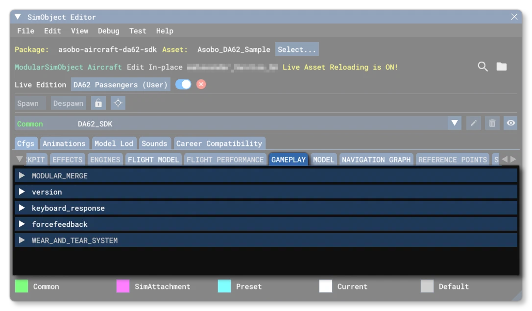
The gameplay.cfg is an optional file for aircraft SimObjects, and is not used by non-aircraft SimObjects. The file is used to define certain gameplay and control elements related to how an aircraft handles within the Microsoft Flight Simulator 2024 world. Below you can find information on the different sections used in the gameplay.cfg file as well as what parameters and values are expected within them.
[Version]
The [Version] section provides version information for the configuration file. In Microsoft Flight Simulator 2024, major versions should always be at least equal to 1.
Note that this section information is mandatory and should always be included.
| Parameter | Description | Type | Required |
|---|---|---|---|
major | Major CFG file version number, values must be greater than 0. | Integer | Yes |
minor | Minor CFG file version number, values must be greater than 0. | Integer | Yes |
[KEYBOARD_RESPONSE]
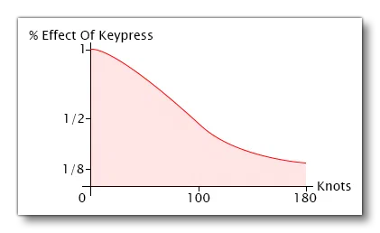
Flight controls naturally become more sensitive as airspeed increases, and so it can become quite difficult to control the aircraft via the keyboard at high speeds. To address this problem, the amount a single key-press increments a flight control is decreased by a factor of 1/2 at the first airspeed (in Knots) listed on the line for the control, and to 1/8 at the second airspeed, and to a scale interpolated from these values for all airspeeds in between. The example below shows that an elevator will increment by one degree when the airspeed is zero, by ¾ of one degree at 50 knots, ½ of one degree at 100 knots, 5/16 of one degree at 140 knots, and 1/8 of one degree at 180 knots or greater speed.
Available parameters are:
| Parameter | Description | Type | Required |
|---|---|---|---|
elevator | The elevator response parameters. This takes two values:
Both values are in Knots. | Listof 2 Floats | Yes |
aileron | The aileron response parameters. This takes two values:
Both values are in Knots. | ||
rudder | The rudder response parameters. This takes two values:
Both values are in Knots. |
[FORCEFEEDBACK]
This section controls the force feedback effects for various aircraft features. The available parameters are:
Parameter
Description
Type
Required
stick_shaker_magnitude
This parameter defines the simulated stick shaker magnitude for the stick or yoke when flying an aircraft equipped with a stick shaker, from 0 to 10000.
Integer
No
stick_shaker_direction
This parameter defines the simulated stick shaker direction for the stick or yoke when flying an aircraft equipped with a stick shaker, from 0 to 35999
Integer
stick_shaker_period
This parameter defines the simulated stick shaker period for the stick or yoke when flying an aircraft equipped with a stick shaker, in microseconds.
Integer
gear_bump_nose_magnitude
Magnitude of gear bump for the nose gear, from 0 to 10000.
These parameters define the simulated forces transferred from the airframe and gear drag to the stick or yoke when the aircraft’s nose and main landing gear is raised or lowered (cycled). In fixed-gear aircraft this effect won’t be felt because, by definition, the landing gear doesn’t move. Different aircraft have different gear geometries that result in each of the gear mechanisms starting and ending its cycle at a different time. The timing deltas are brief, typically less than a second between the time that each gear starts and ends its cycle.
Integer
gear_bump_nose_direction
Direction of gear bump for the nose gear, from 0 to 35999
Integer
gear_bump_nose_duration
Duration of gear bump for the nose gear, in microseconds.
Integer
gear_bump_left_magnitude
Magnitude of gear bump for the left gear, from 0 to 10000.
Integer
gear_bump_left_direction
Direction of gear bump for the left gear, from 0 to 35999
Integer
gear_bump_left_duration
Duration of gear bump for the left gear, in microseconds.
Integer
gear_bump_right_magnitude
Magnitude of of gear bump for the right gear, from 0 to 10000.
Integer
gear_bump_right_direction
Direction of of gear bump for the right gear, from 0 to 35999
Integer
gear_bump_right_duration
Duration of gear bump for the right gear, in microseconds.
Integer
ground_bumps_angle1
First direction value for bumps on the ground, from 0 to 35999.
These parameters collectively define a composite force that simulates the forces felt through an aircraft’s ground steering controls as the aircraft travels over an uneven surface. The parameters are divided into two subgroups (numbered 1 and 2), and define the behavior of two distinct forces. The combination of the two forces define a composite force that is transferred to the stick or yoke. The two forces are both sinusoidal periodic forces, with frequencies determined by the following linear equation:
frequency = (ground_bumps_slope * aircraft_ground_speed) + ground_bumps_intercept
The ground_bumps_magnitude parameters set the magnitude of the force. The ground_bumps_angle parameters set the direction from which the force is felt.
Integer
ground_bumps_magnitude1
First magnitude value for bumps on the ground, from 0 to 10000.
Integer
ground_bumps_intercept1
Floating point number, from 0 to 1,000,000 cycles per second.
Float
ground_bumps_slope1
Floating point number, from 0 to 1,000,000 cycles per second.
Float
ground_bumps_magnitude2
Second magnitude value for bumps on the ground, from 0 to 10000.
Integer
ground_bumps_angle2
Second direction value for bumps on the ground, from 0 to 35999
Integer
ground_bumps_intercept2
Floating point number, from 0 to 1,000,000 cycles per second.
Float
ground_bumps_slope2
Floating point number, from 0 to 1,000,000 cycles per second.
Float
crash_magnitude1
First crash magnitude value, between 0 and 10000.
These parameters define the simulated forces felt in the stick or yoke when the aircraft crashes. The parameters are divided into two subgroups (numbered 1 and 2), and define the behavior of two distinct crash-induced forces. The first force is a constant force that lasts for 0.5 seconds. After 0.5 seconds, it stops and the second force starts. The second force is a periodic square wave force; its amplitude declines linearly to 0.
Integer
crash_direction1
First crash magnitude direction, between 0 and 35999.
Integer
crash_magnitude2
Second crash magnitude value, between 0 and 10000.
Integer
crash_direction2
Second crash magnitude direction, between 0 and 35999.
Integer
crash_period2
Second crash period, in microseconds.
Integer
crash_duration2
Second crash duration, in microseconds
Integer
[WEAR_AND_TEAR_SYSTEM]
This section is for defining some of the properties of the wear and tear system.
Wear and tear is calculated using a number of internal variables to generate a value for each of the applicable parts and systems. These wear and tear values are automatically added into the simulation when a system and its components are added, however it is possible to inhibit many of the wear and tear systems if they do not make sense in the context or your aircraft. This is done through the following parameters:
| Parameter | Description | Type | Required |
|---|---|---|---|
Version | The version of the failure system that you want to use. Available values are:
| Integer / String | No |
inhibitAll | If set to 1 (True) then this will inhibit all the failures on this aircraft, essentially disabling the failure system and meaning you do not need to use the inhibitCategory parameters. | Boolean | No |
inhibitCategory | This parameter permits you to inhibit (disable) entire categories of wear and tear damage, preventing all components within the given category from taking damage and failing. To do this, you need to give a comma separated list of each of the categories that you wish to inhibit, for example: inhibitCategory = Engine, Controls, LandingGear The available categories are as follows:
The parameter has no default value, and if you do not wish to inhibit any categories, simply omit the parameter from the file. Note too that this requires that the | List of strings | No |
inhibitElement | This parameter permits you to inhibit (disable) specific elements within the wear and tear categories such that they no longer take wear and tear damage or can fail. To do this, you need to give a comma separated list of each of the failure categories that you wish to inhibit, for example: inhibitElement = FUEL_TANK.tank_left, FUEL_TANK.tank_right, HYDRAULIC_RESERVOIR, LANDING_GEAR The available elements are as follows:
The listed elements that also have The parameter has no default value, and if you do not wish to inhibit any elements, simply omit the parameter from the file. Note too that this requires that the | List of strings | No |