
navigation_graph.cfg

The [navigation_graph].cfg is an optional file for SimObjects. It is used to define nodes and edges (connections or paths) within a SimObject or an Airport, which permit interactions of some kind to occur. Navigation graph files are normally named using the following naming convention:
navigation_graph_[SimObjName]_<Identifier>.cfg
navigation_graph_[AirportICAO]_<identifier>.cfgnavigation_graph.cfg. This will cause issues, both with the editor and potentially with the simulation itself.The [SimObjName] / [AirportICAO] part is optional, but all files should have a unique identifier string to differentiate them from other files of the same type. Below are a few examples:
navigation_graph_da62_passengers.cfg
navigation_graph_skydivers.cfg
navigation_graph_EGLL_small_gate.cfg
navigation_graph_bus_seat.cfg
The files you create must be placed into a folder labelled navigation_graph. The exact location of this folder will depend on whether they are for a SimObject or for an Airport. For a modular aircraft SimObject it would be one of the following:
[Aircraft Project]\PackageSources\SimObjects\Airplanes\[Aircraft Name]\common\navigation_graph\
[Aircraft Project]\PackageSources\SimObjects\Airplanes\[Aircraft Name]\presets\[Company Name]\[Aircraft Name]\navigation_graph\
[Aircraft Project]\PackageSources\SimObjects\Airplanes\[Aircraft Name]\attachments\[Company Name]\[Attachment Name]\navigation_graph\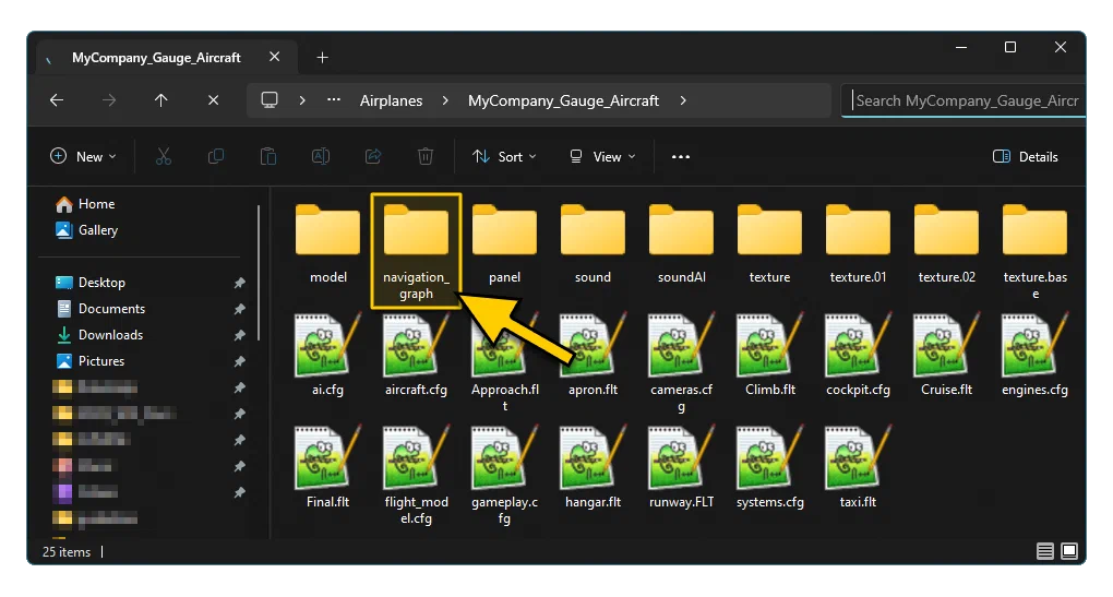
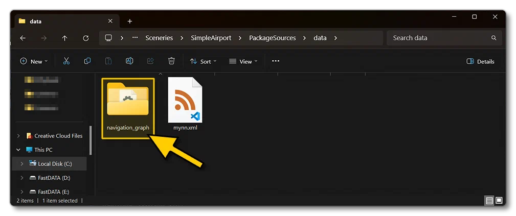
And for an airport it would be:
\[Airport Project\]\(PackageSources\)data\(navigation_graph\)
It should be noted that we do not recommend that you edit these files by hand, and instead you should be using the Node Graph Editor, as explained on the following page:
Also note that for airport projects, the Node Graph Editor should be using the World Coordinate System in the MainGraph section.
Finally, for setting up a navigation graph for use with airport Apron Services and also the various missions available to aircraft, please see here:
[Version]
The [Version] section provides version information for the configuration file. In Microsoft Flight Simulator 2024, major versions should always be at least equal to 1.
Note that this section information is mandatory and should always be included.
| Parameter | Description | Type | Required |
|---|---|---|---|
major | Major CFG file version number, values must be greater than 0. | Integer | Yes |
minor | Minor CFG file version number, values must be greater than 0. | Integer | Yes |
[MainGraph.N]
This section is for defining the contents of the Main Graph for the SimObject. Main graphs should be numbered from N = 0, where each subsequent MainGraph increments N by 1. Note that if indices are not consecutive, later indices will be ignored, for example, if you have MainGraph.0 and MainGraph.2, only MainGraph.0 will be considered by the simulation.
This is the “top level” main graph that will contain a list of all the nodes and (optionally) a list of all the edges assigned to the graph. For example:
[MainGraph.N]
nodes = SKYDIVE_PATH_NODE_0, SKYDIVE_JUMP_NODE
edges = SKYDIVE_PATH_EDGE_0, SKYDIVE_PATH_EDGE_1, SKYDIVE_PATH_EDGE_2
exclusionAreas = 4,5,6
| Parameter | Description | Type | Required |
|---|---|---|---|
nodes | This is a comma separated list of the names of the Node to be included in the Main Graph. | List of strings | Yes |
edges | This is a comma separated list of the names of the Edge to be included in the Main Graph. | List of integers | No |
exclusionAreas | This is a comma separated list of the names of the ExclusionArea to be included in the Main Graph. | List of integers | No |
massSections | This is a comma separated list of the names of the MassSection to be included in the Main Graph. | List of integers | No |
decks | This is a comma separated list of the names of the Deck to be included in the Main Graph. | List of strings | No |
coordinate_system | The coordinate system to use for the nodes in the graph. Can be either of the following:
Default value is: | String | Yes |
[SubGraph.N]
This section is for defining the contents of one or more SubGraph. SubGraphs should be numbered from N = 0, where each subsequent Sub Graph increments N by 1. Note that if indices are not consecutive, later indices will be ignored, for example, if you have SubGraph.0 and SubGraph.2, only SubGraph.0 will be considered by the simulation. Each sub graph has a list of nodes and (optionally) a list of edges which are assigned to the sub graph. For example:
[SubGraph.0]
name = SUB_GRAPH_SEATING
nodes = NODE_PASSAGE_1, NODE_PASSAGE_2
[SubGraph.1]
name = SUB_GRAPH_STEWARDS
nodes = NODE_PASSAGE_1, NODE_POST_1
edges = EDGE_PASSAGE_POST
| Parameter | Description | Type | Required |
|---|---|---|---|
nodes | This is a comma separated list of the names of the Node to be included in the Sub Graph. | List of strings | Yes |
edges | This is a comma separated list of the names of the Edge to be included in the Sub Graph. | List of integers | No |
exclusionAreas | This is a comma separated list of the names of the ExclusionArea to be included in the Sub Graph. | List of integers | No |
massSections | This is a comma separated list of the names of the MassSection to be included in the Sub Graph. | List of integers | No |
decks | This is a comma separated list of the names of the Deck to be included in the Sub Graph. | List of strings | No |
coordinate_system | The coordinate system to use for the nodes in the Sub Graph. Can be either of the following:
Default value is: | String | Yes |
[Node.N]
The [Node.N] section is for defining the individual nodes that will be used by both the [MainGraph.N] and any [SubGraph.N] elements that you create. When defining each node, you should start at N = 0 and increment N by 1 for each node thereafter. Each node has the following parameters:
Parameter
Description
Type
Required
name
The common name assigned to the node and will be used in other parameters to reference the node, and as part of the merge process for the modular SimObject. It is not used in the XML files that reference the navigation graph (for that see Tags, below). This parameter should only contain alpha-numeric characters and the “_” and “-” symbols.
Default value is a dynamic parameter, with the form depending on whether the node is on the main graph or a sub-graph. If the node is not on the main graph, the dynamic param will simply be it’s index, eg:
[Node.N]
name = Index
If the node is on a sub-graph, then it will have the name of the node it’s attached to on the main graph and its index, eg:
[Node.N]
MainGraphNodeName_Index
For example:
[Node.5]
name = SKYDIVE_NODE_START_5
This node is the 5th node on the sub-graph, and is attached to the node named SKYDIVE_NODE_START on the main graph. Note that if the node on the main graph has no name defined, then the parameter will simply be formed as:
[Node.N]
name = MainGraphNodeIndex_Index
String
No
coordinate_system
The coordinate system to use for the node pos. Can be either of the following:
- inherited
world
relative
If this parameter is not included - or is set to “inherited” - the node will inherit the coordinate system defined in the [MainGraph.N] section.
Default value is:
coordinate_system = inheritedString
No
pos
Sets the position of the node being defined based on the coordinate_system of the main or sub graph, where:
- If the parameter is set to “relative” then you give an X/Y/Z offset in ft relative to the Datum Reference Point for the Main Graph, or the parent node if the node is part of a Sub Graph.
- If the parameter is set to “world” then the values are given as lat/lon/alt.
Default value is:
pos = 0,0,0List of floats
No
pbh
Sets the pitch/bank/heading of the node, relative to either:
- The SimObject orientation if the node is part of the Main Graph.
- The “parent” node orientation if the node is part of a Sub Graph.
Default value is:
pbh = 0,0,0List of floats
No
modelNode
This is where you can give a model node name from the aircraft glTF to place the navigation graph node on. If supplied, the pos and pbh set for the navigation graph node will be ignored, and it will be positioned and oriented based on the model node position and orientation. If the parameter is set to the default value, omitted, or set to “NONE”, then the pos and pbh values will be used to manually position the node. Note that the model node name should be enclosed in quotes “”.
Default value is:
modelNode = ""String
No
tag
This is a string that is used to name the node, and can be shared by multiple nodes within multiple files (unlike the name parameter, which should be unique to the node being defined). This name can then be used to identify the node - or group of nodes - in any mission or service XML that requires it. For example, all seat objects for passengers would be on nodes tagged as “SEATS”.
Default value is:
tag = NONEString
No
sharedSeat
This is only required if you want to have the copilot node of the navigation_graph_pilot.cfg (explained here) accept a passenger when the node does not have a copilot assigned. To use this, the node must be tagged with both the COPILOT tag and also the SIT tag, and then include this paramater, set to true.
Default value is:
sharedSeat = falseBool
No
subgraph
The Sub Graph that the node should be added to. Note that you can only assign a node to a single sub graph, not multiple. If this parameter is included, you may also include the edgeToMainNode parameter.
Default value is:
subgraph = ""Integer
No
loadVolume
This defines the three dimensional volume associated with the node, using values for the width/height/depth. The defined volume is the approximate space that any payload on the node would occupy (whether it is a passenger, a suitcase, a bag of rice, etc…).
Default values are:
loadVolume = 0,0,0List of floats
No
spawnLoad
This defines whether a load should be spawned automatically on the node. When set to true (1) then a load will be spawned based on the settings within the mission. If set to false (0) then nothing will be spawned by default. Note that this parameter is only relevant to navigation_graphg_cargo.cfg files (see Aircraft Loads for more information).
Default value is:
spawnLoad = falseBool
No
massSection
The name of one or more [MassSection.N] to be associated with this node. The name will also be applied to the nodes of any sub-graph attached to the node, as well as the nodes of the interaction object spawned on the node (if any). Note that you may have multiple mass sections assigned to a single node, in which case they are given as a comma separated list, eg:
massSection = Rear_left_cargo, Rear_right_cargoDefault value is:
massSection = ""String
No
node_occlusion_factor
This sets the factor with which to modify the base ambient occlusion factor for the SimObject, as set in the SimObject Editor tab using the interior_occlusion_factor parameter. If the node is on a Sub Graph, this value will instead be used to modify the Main Node factor.
Default value is:
node_occlusion_factor = 1Float
No
distanceToNotAnimate
This defines the distance (in meters) from the camera at which any object on this node will stop being animated. If the value is set to -1, then the object will always be animated.
Default value is:
distanceToNotAnimate = -1Float
No
projectOnGround
When this is set to true (1), the height of the node is ignored and instead the height will be that of the ground (essentially the node is projected onto the ground).
Default value is:
projectOnGround = falseBool
No
isEnter
When this is set to true (1) the node will be considered an “entry node”. An entry node is one where an object actor “enters” the current navigation graph from another one.
Default value is:
isEnter = falseBool
No
isExit
When this is set to true (1) the node will be considered an “exit node”. An exit node is one where an object actor can move to and then connect to a different navigation graph.
Default value is:
isExit = falseBool
No
mouserectLinked
Defines a MouseRect to which the node is linked to.
Default value is:
mouserectLinked = ""String
No
edgeToMainNode
This option is only applicable if the node being defined is part of a subgraph. In that case, when this is set to 1 (TRUE), an edge will be created between the sub graph node and the “parent” node on the Main Graph.
Default value is 0 (FALSE):
edgeToMainNode = 0Bool
No
interactiveObject
The name of an interactive object that is to be associated with the node.
Default value is:
interactiveObject = ""String
No
interactiveVolume
This defines the three dimensional volume associated with the node, using values for the width/height/depth. The volume given will be used to determine where interactions will be triggered.
Default values are:
interactiveVolume = 0,0,0List of floats
No
interactiveVolumeOffset
This defines the offset of the interactive volume from the node along the X/Y/Z axis.
Default values are:
interactiveVolumeOffset = 0,0,0List of floats
No
interactiveVolumeConstraint
This sets a constraint on which object actors can trigger the volume interaction. Available options are as follows:
- PlayerAvatarOnly - Only the player avatar
- PlayerAircraftOnly - Only the player aircraft
- PlayerOnly - Only the player avatar and/or the player aircraft.
- RegisterOnly - Only the objects previously registered with “RegisterForInteractionVolume” in the navigation service XML will trigger the interaction volume.
- None - Any simobject
Default value is:
interactiveVolumeConstraint = "PlayerAvatarOnly"String
No
interactionVolume
Here you can add a GUID reference to a <ServiceInteraction.InteractionVolume> element of a Service Interaction XML file used by the aircraft.
interactionFile.n parameter.String
No
interactionState
Here you can add a GUID reference to a <ServiceInteraction.InteractionState> element of a Service Interaction XML file used by the aircraft.
interactionFile.n parameter.String
No
interactionGUID.n
Here you can add one or more GUID references to the <ServiceInteraction.Interaction> elements of a Service Interaction XML file used by the aircraft. Each GUID should be assigned to a unique interactionGUID, which should be numbered from 0 and then in sequence. For example:
interactionGUID.0 = {47A41889-4F09-47D5-AE2F-D101BA03D150}
interactionGUID.1 = {6ECC5EFB-6EB4-4E0F-A30B-1A695BFA4D32}interactionFile.n parameter.List of strings
No
interactionFile.n
A path of an interaction XML file to load. If the XML has a <ServiceInteraction.InteractionState> element or a <ServiceInteraction.InteractionVolume> element and the node does not already have one, then it will be assigned. Each interaction file listed will have its own spawner.
Note that it is possible to include additional parameters to be used as string substitutions within the XML. This requires that the parameter be formatted as a hashmap where:
- #FilePath - This key defines the path to the interaction XML
- #Param - this key defines one or more XML strings to be substituted.
For example:
interactionFile.0 = FilePath: InteractionsPreset\Asobo\Seat\Seatbelt # Param: SEATBELT_FASTEN:SEATBELT_C172_Pilot_FastenIn the above example, all mentions of the string “SEATBELT_FASTEN” will instead be read as “SEATBELT_C172_Pilot_Fasten”. You can pass in several parameters in this way simply by separating them with a comma, for example:
interactionFile.1 = FilePath: InteractionsPreset\Asobo\Seat\Seatbelt # Param: SEATBELT_FASTEN:SEATBELT_C208B_PAX_1_Fasten, SEATBELT_UNFASTEN:SEATBELT_C208B_PAX_1_UnfastenString
No
[Edge.N]
The [Edge.N] section is for defining the individual edges (paths) that connect any two nodes together. When defining each edge, you should start at N = 0 and increment N by 1 for each edge thereafter.
| Parameter | Description | Type | Required |
|---|---|---|---|
name | The common name assigned to the edge and will be used to reference the edge in other parameters. Should only contain alpha-numeric characters and the "_" and "-" symbols. Default value is a dynamic parameter formed as: For example: Note that if the nodes have no names defined, then the parameter will simply be formed as: | String | No |
nodeStart | The name of the [Node.N] that should be considered as the first node of the edge connection. | String | Yes |
nodeEnd | The name of the [Node.N] that should be considered as the last node of the edge connection. | String | Yes |
[ExclusionArea.N]
The [ExclusionArea.N] section is for defining an area that will invalidate any edge that crosses it, such that no behaviour can move on it. This is useful when using interactive objects linked by multiple edges to the main graph. These areas should be defined as a set of at least 3 nodes that form a closed polygon. For example:
[ExclusionArea.0]
nodes = NODE_EXCLUDE_1, NODE_EXCLUDE_2, NODE_EXCLUDE_3, NODE_EXCLUDE_4
When defining each exclusion area, you should start at N = 0 and increment N by 1 for each area thereafter. Each exclusion area has the following parameters:
| Parameter | Description | Type | Required |
|---|---|---|---|
name | The common name assigned to the exclusion area. Should only contain alpha-numeric characters and the "_" and "-" symbols. Default value is: | String | No |
nodes | This is a comma separated list of the names of the nodes to be used to define the exclusion area. There must be at least three nodes in the list for a valid exclusion area to be formed. | List of strings | Yes |
[MassSection.N]
The [MassSection.N] section is used to apply the mass of the behaviours of a navigation service to the SimObject holding the navigation service.
When a behaviour is attached to a SimObject, it applies (or removes) its mass at the end of each of its movements along the navigation graph, or when it gets attached or detached. The position at which its mass is applied will depend on the position defined for the station_load.N that the mass section references. For example:
[MassSection.0]
name = ecoSeats
stationLoadName = seat_rows_left
maxMass = 500
When defining each mass section, you should start at N = 0 and increment N by 1 for each section thereafter. Each mass section has the following parameters:
| Parameter | Description | Type | Required |
|---|---|---|---|
name | The common name assigned to the mass section. Should only contain alpha-numeric characters and the "_" and "-" symbols. Default value is: | String | No |
stationLoadName | Sets the name of the station load (as defined by the | List of floats | Yes |
maxMass | The maximum mass (in lbs) that can be applied in this mass section. If more than the amount specified is applied, then it will be clamped to this amount. Default value is: Note that a value of -1 means that the value is uncapped. | Float | No |
fillProportion | The value here is used to determine the default placement configuration of mass as it is added to the nodes. For example, if you have mass section [0] with a fill proportion of 4, and mass section [B] with a fill proportion of 2, then the percentage of SimObjects that will be sent to [A] is 66% and to [B], 33%. Default value is: Note that a value of 0 means that there is no fill proportion and each mass area will be filled until the | Integer | No |
fillPriority | The value here is used to determine the order in which sections will be filled, where those with the lowest value will be the first to fill. Note that this works in conjunction with Note that there is no default value, and if you do not assign a fill priority, then the section will be considered as having a maximum value (ie: last to fill). | Integer | No |
deck | This the name of the | Integer | No |
[Deck.N]
The [Deck.N] section is used to define different decks of an airliner or other multi-deck aircraft. Having defined a deck, this is then assigned to one or more [MassSection.N]. For example:
[Deck.0]
name = firstFloor
deckName = TT:DECKNAME
deckOrder = 1
[MassSection.0]
name = Pilot
stationLoadName = PILOT
maxMass = 1000
fillProportion = 1
deck = firstFloor
Currently this section is only relevant to the EFB to correctly display the nodes of multi-deck planes, with a name for each deck.
When defining each deck, you should start at N = 0 and increment N by 1 for each section thereafter. Each mass section has the following parameters:
| Parameter | Description | Type | Required |
|---|---|---|---|
name | The common name assigned to the deck. Should only contain alpha-numeric characters and the "_" and "-" symbols. Default value is: | String | No |
deckName | The public name of the deck, which will be used for display in the EFB. This text can be localised. | String | Yes |
deckOrder | An integer value used to set the order of the decks, with the lowest deck being at 0, and subsequent decks adding to this. | Integer | Yes |