
Electric System Setup Information
On this page you can find additional information and parameters that are used when setting up the Electrical Systems for an aircraft.
Numeric Inputs
Previous iterations of electrical systems in FSX and Microsoft Flight Simulator 2020 used either a curve or a value as part of the input, and if you used a curve then it would be automatically interpolated based on the component properties (APU, engine generator, battery voltage, etc…). However this led to a certain inflexibility in the setup of the electrics, and as such the current system has removed these hard-coded dependencies as much as possible, meaning that any numeric input is now either a parameter constant or a curve.
The two types of parameter constants that can be used as numeric input are as follows:
SimVars: For example you can use the following to get the first engine RPM.
[data.simvar(GENERAL ENG RPM:1, rpm)]Global Variables: For example the following gets the global (user created) variable
GLOBAL_VARas a boolean.[data.globalvar(GLOBAL_VAR, bool)]
Here is a full example setting up a Generator where a constant parameter is being used, the SimVar GENERAL ENG PCT MAX RPM, along with a curve:
generator.1 = Name:LH_ACGenerator # Vrms:115 # PowerRating:90 # GovernedRPM:[data.simvar(GENERAL ENG RPM:1, rpm)] #ReferenceRPM:2000 #ReferenceFrequency:400These different types of parameter constant can be used directly as an input for any hash-map parameter in any component in the electrical system.
It is worth noting that for curves you can supply an additional value to re-map the curve that has been given to be within a different range. The supplied value should be enclosed in () after the curve path, for example:
/* A curve */
curve.1 = Name:MyCurve #Points: 100:0, 500:27, 800:28
/* Using that curve to remap the aircraft ram air RPM to a voltage */
supplier.1 = (...) GovernedRPM:[curve.MyCurve([data.simvar(GENERAL ENG RPM:1, rpm)])]
If you are unsure what value to use then simply supply a 1 so no re-mapping is applied.
Finally, some commonly used real life values are exposed for your use as parameters, such as the chemical voltage of a cell given its current capacity for different compositions, eg: Lithium-Ion, NiCad, etc… You can find these built-in values from the links below:
Consumers/Suppliers And Inline Setup
It is important to be aware of the fact that all Supplier and Consumer data should be in one place, ie: it can be in either a supplier, or a consumer, but not in both. If a supplier/consumer is given to a component as part of the component definition, then all other supplier/consumer parameters given directly in the item definition will be ignored. Essentially, supplier/consumer configurations have priority over “inline” configurations.
Consider the following consumer and circuit definitions:
consumer.6 = Name:ConsumerStarter #Voltage:24 #Wattage:3500
consumer.7 = Name:ConsumerFuelPump #Voltage:24 #Amperage:2
circuit.4 = Type:CIRCUIT_STARTER #ConsumerCfg:ConsumerStarter #Name:StarterB
circuit.5 = Type:CIRCUIT_PITOT_HEAT #Voltage:12 #Wattage:40 #Name:PitotHeat
circuit.6 = Type:CIRCUIT_FUEL_PUMP #ConsumerCfg:ConsumerFuelPump #Wattage:48 #Name:FuelPumpA #WearAndTearCollision:GlobalDamage
In the example above, circuits 4 and 5 are valid, but in circuit 6, the wattage will be ignored because a consumer configuration has already been given, and so the information from the consumer will be used.
Cell Types
The following built-in battery cell types are available for use in the Supplier component. These are simply easy to remember parameters that are used instead of hard-coding the underlying Curve values. In the tables below, the values given here for the curves are for a single cell of the given battery type.
The C-rate represents the amount of time in which the battery goes from fully charged to empty, 1C means the battery empties in 1 hour. In the simulation, we use curves measured at 0.1 C-rate for the low loads (ie: 10 hours of battery life), and 15 C-rate for the high loads (4 minutes of battery life).
LithiumIonUsing this parameter you’ll get the values appropriate for a battery of the type lithium ion. This battery has the following curves:
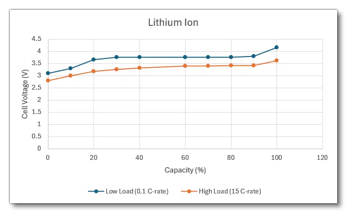
State of Charge % (”SOC”) Low Load Cell Voltage (V)(0.1 C-rate) High Load Cell Voltage (V)(15 C-rate) 0 3.1 2.8 10 3.3 3.0 20 3.65 3.18 30 3.75 3.25 40 3.75 3.32 60 3.75 3.39 70 3.75 3.395 80 3.75 3.405 90 3.8 3.41 100 4.15 3.62 NiZnUsing this parameter you’ll get the values appropriate for a battery of the type nickel-zinc. This battery has the following curves:
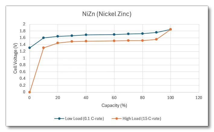
State of Charge % (”SOC”) Low Load Cell Voltage (V)(0.1 C-rate) High Load Cell Voltage (V)(15 C-rate) 0 1.3 0 10 1.6 1.3 20 1.64 1.45 30 1.66 1.49 40 1.69 1.5 60 1.70 1.51 70 1.71 1.52 80 1.72 1.52 90 1.76 1.55 100 1.85 1.85 LeadAcidUsing this parameter you’ll get the values appropriate for a battery of the type lead-acid. This battery has the following curves:
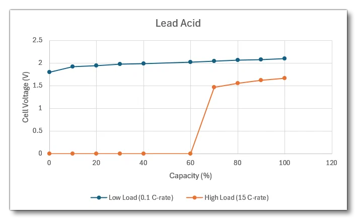
State of Charge % (”SOC”) Low Load Cell Voltage (V)(0.1 C-rate) High Load Cell Voltage (V)(15 C-rate) 0 1.8 0 10 1.92 0 20 1.94 0 30 1.97 0 40 1.99 0 60 2.02 0 70 2.04 1.46 80 2.06 1.55 90 2.08 1.62 100 2.1 1.66 NiCdUsing this parameter you’ll get the values appropriate for a battery of the type nickel-cadmium. This battery has the following curves:
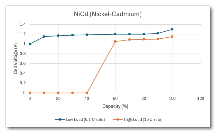
State of Charge % (”SOC”) Low Load Cell Voltage (V)(0.1 C-rate) High Load Cell Voltage (V)(15 C-rate) 0 1 0 10 1.15 0 20 1.17 0 30 1.18 0 40 1.19 0 60 1.2 1.05 70 1.2 1.09 80 1.2 1.095 90 1.22 1.1 100 1.3 1.15
You can see how these battery parameters are used in the example below:
supplier.1 = Name:SupplierBatteryA #SType:Battery #BatteryType:NiCd
battery.1 = Name:MAIN_BATTERY #ConsumerCfg:ConsumerBatteryA #SupplierCfg:SupplierBatteryA
To compute the output voltage of a battery, the simulation estimates the voltage for one cell from low and high voltage curves, depending on battery type. It first determines the C-rate from the load currently drawn from the battery, and then an interpolation is performed to get a voltage value between the low and high load voltage curves. Once the simulation has calculated the voltage of one cell, it is multiplied by the number of cells in the battery that was determined from the battery nominal voltage at the time of the aircraft spawning.
With this method, output voltage depends on the state of the battery charge and load, as well as the Wear and Tear amount, ie: more load, more wear, and less remaining capacity, will all result in less voltage output.
Trip Curves
A trip curve is used to define how much of an overload a Connection component can sustain before tripping the Breaker. The overload is based on IEC(opens in a new tab) and IEEE(opens in a new tab) formulas that give a duration before overload for a given load and design load. Within the simulation these have been transferred into built in parameters that you can use, following the format as outlined in the section on Numeric Inputs. For example:
breaker.1 = Name:A_Breaker # RatedCurrent:5 # TripCurveType:IEC_VinvThe main trip-curves relating to both standards are built into the simulation as easy to remember parameters which can be used where necessary:
| Parameter | Description | Curve Values | Formula |
|---|---|---|---|
IEC_Sinv | Standard inverse trip curve. | 0.14, 00.2 | $$\frac{k}{(\frac{I}{I_S})^a - 1}$$Curve values are (k, a) |
IEC_Vinv | Very inverse trip curve. | 13.5, 1 | $$\frac{k}{(\frac{I}{I_S})^a - 1}$$Curve values are (k, a) |
IEC_Einv | Extremely inverse trip curve. | 80, 2 | $$\frac{k}{(\frac{I}{I_S})^a - 1}$$Curve values are (k, a) |
IEC_LTSinv | Long time standard inverse trip curve. | 120, 1 | $$\frac{k}{(\frac{I}{I_S})^a - 1}$$Curve values are (k, a) |
IEEE_Vinv | Very inverse trip curve. | 19.61, 0.491, 2 | $$\frac{A}{(\frac{I}{I_S})^p - 1} + B$$Curve values are (A, B, p) |
IEEE_Minv | Moderately inverse trip curve. | 28.2, 0.1217, 2 | $$\frac{A}{(\frac{I}{I_S})^p - 1} + B$$Curve values are (A, B, p) |
IEEE_Einv | Extremely inverse trip curve. | 0.0515, 0.114, 0.02 | $$\frac{A}{(\frac{I}{I_S})^p - 1} + B$$Curve values are (A, B, p) |
Circuit Types
When defining any circuit.N for the electrical system, the first parameter of the hash-map is a variable that defines the type of circuit. The table below shows all the variables that correspond to each of the available types as well as a brief description of what that circuit controls.
| Type | Index | Description |
|---|---|---|
CIRCUIT_INVALID | 0 | Invalid circuit which has no direct impact on sim state. |
CIRCUIT_XML | 1 | Generic circuit which has no direct impact on sim state, and is designed for use when creating your own custom behaviours logic. |
CIRCUIT_GENERAL_PANEL | 2 | Circuit checked for general power availability. |
CIRCUIT_FLAP_MOTOR | 3 | Circuit turned on when flaps are moving (if electrical). |
CIRCUIT_GEAR_MOTOR | 4 | Circuit turned on when landing gears are moving (if electrical). |
CIRCUIT_AUTOPILOT | 5 | Circuit checked for autopilot availability. |
CIRCUIT_AVIONICS | 6 | Circuit checked for avionics availability. |
CIRCUIT_PITOT_HEAT | 7 | Circuit controlling pitot heat state. |
CIRCUIT_PROP_SYNC | 8 | Circuit controlling prop sync. |
CIRCUIT_AUTO_FEATHER | 9 | Circuit controlling auto feathering.NOTE: Please see the Note On Autofeathering for more information. |
CIRCUIT_AUTO_BRAKES | 10 | Circuit controlling auto brakes. |
CIRCUIT_STANDBY_VACUUM | 11 | Circuit controlling standby vacuum. |
CIRCUIT_MARKER_BEACON | 12 | Circuit checked for beacon marker system availability. |
CIRCUIT_GEAR_WARNING | 13 | Circuit checked for gear warning system availability. |
CIRCUIT_HYDRAULIC_PUMP | 14 | Circuit controlling a [HYDRAULIC_SYSTEM_EX1] pump (one circuit per-pump only, you cannot control multiple pumps off a single circuit). See the section on Pump.N for more information. |
CIRCUIT_HYDRAULIC_VALVE | 15 | Circuit controlling a [HYDRAULIC_SYSTEM_EX1] valve (one circuit per-valve only, you cannot control multiple valve off a single circuit). See the section on Valve.N for more information. |
CIRCUIT_FUEL_PUMP | 16 | Circuit controlling a [FUEL_SYSTEM] electrical pump (one circuit per-pump only, you cannot control multiple pumps off a single circuit). See the section on Pump.N for more information. |
CIRCUIT_FUEL_TRANSFER_PUMP | 17 | Circuit controlling electrical fuel transfer pumps. |
CIRCUIT_PROP_DEICE | 18 | Circuit controlling prop deicing. |
CIRCUIT_STARTER | 19 | Circuit controlling electrical starter state. |
CIRCUIT_LIGHT_NAV | 20 | Circuit controlling navigation light state. |
CIRCUIT_LIGHT_BEACON | 21 | Circuit controlling beacon light state. |
CIRCUIT_LIGHT_LANDING | 22 | Circuit controlling landing light state. |
CIRCUIT_LIGHT_TAXI | 23 | Circuit controlling taxi light state. |
CIRCUIT_LIGHT_STROBE | 24 | Circuit controlling strobe light state. |
CIRCUIT_LIGHT_PANEL | 25 | Circuit controlling panel light state. |
CIRCUIT_LIGHT_RECOGNITION | 26 | Circuit controlling recognition light state. |
CIRCUIT_LIGHT_WING | 27 | Circuit controlling wing light state. |
CIRCUIT_LIGHT_LOGO | 28 | Circuit controlling logo light state. |
CIRCUIT_LIGHT_CABIN | 29 | Circuit controlling cabin light state. |
CIRCUIT_LIGHT_PEDESTAL | 30 | Circuit controlling pedestal light state. |
CIRCUIT_LIGHT_GLARESHIELD | 31 | Circuit controlling glareshield light state. |
CIRCUIT_DIRECTIONAL_GYRO | 32 | Circuit checked for directional gyro system availability. |
CIRCUIT_DIRECTIONAL_GYRO_SLAVING | 33 | Circuit checked for directional gyro slaving system availability. |
CIRCUIT_NAV | 34 | Circuit checked for NAV system availability. |
CIRCUIT_COM | 35 | Circuit checked for COM system availability. |
CIRCUIT_PFD | 36 | Circuit checked for PFD system availability.Currently not used in the simulation, but can be used in custom behaviour logic. |
CIRCUIT_MFD | 37 | Circuit checked for MFD system availability.Currently not used in the simulation, but can be used in custom behaviour logic. |
CIRCUIT_ADC_AHRS | 38 | Circuit checked for ADC and AHRS system availability.Currently not used in the simulation, but can be used in custom behaviour logic. |
CIRCUIT_FIS | 39 | Circuit checked for FIS system availability.Currently not used in the simulation, but can be used in custom behaviour logic. |
CIRCUIT_ADF_DME | 40 | Circuit checked for ADF and DME system availability.Currently not used in the simulation, but can be used in custom behaviour logic. |
CIRCUIT_XPNDR | 41 | Circuit checked for transponder system availability. |
CIRCUIT_TURN_COORDINATOR | 42 | Circuit checked for turn coordinator system availability. |
CIRCUIT_AUDIO | 43 | Circuit checked for audio system availability. |
CIRCUIT_AVNFAN | 44 | Circuit checked for avionics fan system availability.Currently not used in the simulation, but can be used in custom behaviour logic. |
CIRCUIT_GPS | 45 | Circuit checked for avionics GPS system availability. |
CIRCUIT_INST | 46 | Currently not used in the simulation, but can be used in custom behaviour logic. |
CIRCUIT_INST_LIGHTS | 47 | Currently not used in the simulation, but can be used in custom behaviour logic. |
CIRCUIT_ALTFLD | 48 | Currently not used in the simulation, but can be used in custom behaviour logic. |
CIRCUIT_WARN | 49 | Currently not used in the simulation, but can be used in custom behaviour logic. |
CIRCUIT_LTS_PWR | 50 | Currently not used in the simulation, but can be used in custom behaviour logic. |
CIRCUIT_ATTITUDE_INDICATOR | 51 | Circuit checked for attitude indicator availability (if electrical). |
CIRCUIT_STALL_WARNING | 52 | Circuit checked for stall warning availability (if electrical). |
CIRCUIT_APU_STARTER | 53 | Circuit controlling APU starter state.NOTE: While it appears that you can define multiple APU circuits in an aircraft, currently the simulation will only permit one APU definition to work. This may change in future updates. |
CIRCUIT_FUEL_VALVE | 54 | Circuit controlling a [FUEL_SYSTEM] valve (one circuit per-valve only, you cannot control multiple valves off a single circuit). See the section on Valve.N for more information. |
CIRCUIT_WING_FOLD | 55 | Circuit controlling the wing folding system (if available). |
CIRCUIT_ELECTRIC_ENGINE | 56 | Circuit controlling the electric engine (if available). |
CIRCUIT_PNEUMATICS_VALVE | 57 | Circuit controlling a [PNEUMATIC_SYSTEM_EX1] valve (one circuit per-valve only, you cannot control multiple valves off a single circuit). See the section on Valve.N for more information. |
CIRCUIT_PNEUMATICS_PACK | 58 | Circuit controlling a [PNEUMATIC_SYSTEM_EX1] pack (one circuit per-pack only, you cannot control multiple packs off a single circuit). See the section on Pack.N for more information. |
CIRCUIT_CABIN_SIGNAL_GO | 59 | Circuit controlling the “go” light of the inside cabin (for skydiving and other activities). |
CIRCUIT_CABIN_SIGNAL_STANDBY | 60 | Circuit controlling the “standby” light of the inside cabin (for skydiving and other activities). |
CIRCUIT_CABIN_SIGNAL_STOP | 61 | Circuit controlling the “stop” light of the inside cabin (for skydiving and other activities). |
CIRCUIT_LIQUID_DROPPING_DOOR | 62 | Circuit controlling a [Liquid Dropping System] door. See the section on Door.N for more information. |
CIRCUIT_LIQUID_DROPPING_SCOOP | 63 | Circuit controlling a [Liquid Dropping System] scoop. See the section on Scoop.N for more information.Currently not used in the simulation, but can be used in custom behaviour logic. |
CIRCUIT_ROTOR_BRAKE | 64 | Circuit controlling the rotor brake (helicopters only). |
CIRCUIT_HOIST | 65 | Circuit controlling the hoist, if available. |
CIRCUIT_SLING | 66 | Circuit controlling the sling, if available. |
CIRCUIT_PNEUMATICS_FAN | 67 | Circuit controlling a [PNEUMATIC_SYSTEM_EX1] fan. See the section on Fan.N for more information. |
CIRCUIT_ROTOR_CLUTCH | 68 | Currently not used in the simulation, but can be used in custom behaviour logic. |
CIRCUIT_INTERACTIVE_POINT | 69 | Currently not used in the simulation, but can be used in custom behaviour logic. |
CIRCUIT_DEICE | 70 | Circuit controlling the DEICE_SYSTEM when this is set to structural deice type 4 (electrical). Note that only the first circuit defined of this type will actually control the structural deicing system, and so it will only run when this circuit is on. |
Key Events
The table below shows the different key event IDs that can be used to modify things within the electrical system of an aircraft. These are often used along with the Aircraft Electrics Variables to control the electrical systems with the aircraft. For more details on how to use these events, please see here: Event ID’s As Key Events.