
systems.cfg
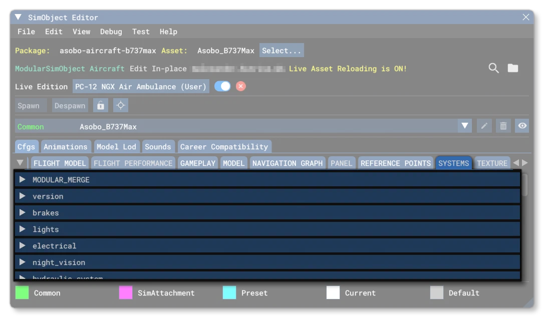
The systems.cfg is an optional file for SimObjects, unless you are creating an aircraft in which case it is mandatory. This file is used for defining various different aircraft systems. Below you can find information on the different sections used in the systems.cfg file as well as what parameters and values are expected within them.
[Version]
The [Version] section provides version information for the configuration file. In Microsoft Flight Simulator 2024, major versions should always be at least equal to 1.
Note that this section information is mandatory and should always be included.
| Parameter | Description | Type | Required |
|---|---|---|---|
major | Major CFG file version number, values must be greater than 0. | Integer | Yes |
minor | Minor CFG file version number, values must be greater than 0. | Integer | Yes |
[BRAKES]
This section controls the aircraft’s brake systems. Available parameters are:
| Parameter | Description | Type | Required |
|---|---|---|---|
brakes_aircraft_weight_ratio | This defines the ratio of the total aircraft empty weight that each braking system weighs.Default value is 0.0005. | Float | No |
brakes_cooling_factor | This scalar is used to set the rate at which brakes will cool down when stopped.Default value is 0.001. | Float | No |
brakes_cooling_factor_100kts | This scalar is used to set the speed at which brakes will cool down when moving at 100KnotsDefault value is 0.02. | Float | No |
brakes_wear_factor | This scalar is used to set the speed at which brakes will wear down.Default value is 0.00001. | Float | No |
brakes_min_brake_effect_kelvin | This defines the temperature at which the brakes are 100% effective (in Kelvin).Default value is 423.15. | Float | No |
brakes_max_brake_effect_kelvin | This deifnes the temperature at which the brakes are minimally effective (in Kelvin).Default value is 623.15. | Float | No |
brakes_temperature_effect | This defines the ratio of effectiveness of the brakes when at the temperature defined by the brakes_min_brake_effect_kelvin parameter.Default value is 0.75. | Float | No |
parking_brake | The type of parking brake available.Default value is 1. | Integer:0 = none1 = parking brake2 = ground restraint brake | No |
differential_braking_scale | Differential braking is a function of using both brakes and the rudder pedal input. The amount of difference between the left and right brake is scaled by this value. Setting this to 0.0 means no differential braking is desired, while a setting of 1.0 is the normal setting for when differential braking is desired - which is particularly useful for tailwheel airplanes.Default value is 0. | Float | No |
toe_brakes_scale | Sets the scaling of the toe braking effectiveness, expressed as a Percent Over 100. Note that a setting of 0.0 scales the brakes to no effectiveness.Default value is 1. | Float | No |
no_toe_brake_input_smoothing | Whether to disable (TRUE, 1) or not (FALSE, 0) input smoothing for toe brakes.Default value is 0 (FALSE). | Bool | No |
toe_brakes_pressure_increment | This value defines the maximum pressure that will be applied by the toe-brakes when used, expressed as a Percent Over 100.Default value is 0.033. | Float | No |
toe_brakes_pressure_release_delay | This value sets the time (in seconds) after which the toe-brake pressure will start to decay.Default value is 0.25. | Float | No |
toe_brakes_pressure_decrease_tc | This value is the time constant (factor) that will be used to determine the speed at which toe-brake pressure will decay.Default value is 3.0 | Float | No |
parking_brake_linked_to_toe_brakes | This parameter governs whether the parking brake will release upon application of the toe brakes.Default value is 1 (TRUE), but a setting of 0 (FALSE) will prevent this behavior. | Bool | No |
hydraulic_system_scalar | On brakes dependent on the hydraulic system, this is the ratio of hydraulic system to maximum brake hydraulic pressure.Default value is 0. | Float | No |
show_brake_message | Whether to show the braking message (TRUE, 1) or not (FALSE, 0) in the UI.Default value is 1 (TRUE). | Bool | No |
auto_brakes | The number of autobrakes available (0 means no autobrakes).Default value is 0. | Integer | No |
autobrakes_disabled_on_takeoff | Whether the autobrake is disabled (TRUE, 1) or not (FALSE, 0) for takeoff.Default value is 0 (FALSE). | Bool | No |
autobrakes_requires_antiskid | Whether the autobrake systems require anti-skid (TRUE, 1) or not (FALSE, 0).Default value is 0 (FALSE). | Bool | No |
autobrakes_disabled_on_braking | Whether the autobrake is disabled (TRUE, 1) or not (FALSE, 0) when manually braking.Default value is 0 (FALSE). | Bool | No |
autobrakes_disabled_on_thrust | Whether the autobrake is disabled (TRUE, 1) or not (FALSE, 0) on reverse thrust.Default value is 0 (FALSE). | Bool | No |
autobrakes_disabled_on_stop | Whether the autobrake is disabled (TRUE, 1) or not (FALSE, 0) when the plane stops after a landing.Default value is 0 (FALSE). | Bool | No |
rto_disabled_on_stop | Whether the autobrake is automatically disabled (TRUE, 1) or not (FALSE, 0) when the aircraft stops after an RTO.Default value is 0 (FALSE). | Bool | No |
rto_disabled_on_takeoff | Whether the autobrake is disabled (TRUE, 1) or not (FALSE, 0) for an RTO.Default value is 0 (FALSE). | Bool | No |
rto_min_speed_for_trigger | This sets the minimum speed (in Knots) at which an RTO will be activated when moving all throttles to idle.Default value is 85. | Float | No |
[GEAR_WARNING_SYSTEM]
This section defines the functionality of the gear warning system for the aircraft. This is generally related to the throttle lever position and the flap deflection. Available parameters are:
| Parameter | Description | Type | Required |
|---|---|---|---|
gear_warning_available | Sets the type of gear warning system available on the aircraft. | Integer:0 = None1 = Normal2 = Amphibian(audible alert for water vs. land setting) | Yes |
pct_throttle_limit | The throttle limit, below which the gear warning will activate if the gear is not down and locked while the flaps are deflected to at least the setting for flap_limit_idle below. This flap limit can be 0 so that the warning effectively is a function of the throttle. A value between: 0 (idle) and 1.0 (Max throttle).Default value is 0. | Float | No |
flap_limit_idle | This limit is the flap deflection above which the warning will activate if the gear is not down and locked while the throttle is below the limit specified by pct_throttle_limit. Setting this limit to a value greater than 0, the pilot can reduce the throttle to idle without activating the warning (this is often utilized in jets to decelerate/descend the aircraft).Default value is 0. | Float | No |
flap_limit_power | The flap limit, above which the warning will activate (regardless of throttle position).Default value is 0. | Float | No |
[LIGHTS]
This section controls the lights on the aircraft. The given index value can then be passed to the corresponding light SimVar to apply a different behavior to different lights. Note that there is an additional option in The SimObject Editor to enable/disable the light in the simulation for testing, but this option is not included in the associated CFG file: Turn Light On / Off. This option will only work if is enabled:
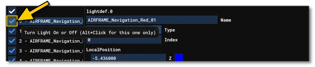
Available parameters are:
| Parameter | Description | Type | Required |
|---|---|---|---|
lightdef.N | Each light has it’s own definition as a hash map (explained below) where each item in the table has it’s own definition. Lights are numbered from 0. | Hash Map | No |
The hash map that each light takes is comprised of the following key:value pairs, separated by the # symbol:
| Key | Value | Description | Required |
|---|---|---|---|
Name | String | This is a name string that is used as an alias to identify the light. It will also be used as the reference index for SimVars, and note that the name is the only guaranteed reference to the component due to the fact that the Modular Aircraft Merging process may change the index. The name cannot contain special characters or spaces. Note that this can be edited directly in the simulation when Live Edition is enabled. | Yes |
Type | Integer:1 = Beacon2 = Strobe3 = Navigation or Position4 = Panel (Interior only)5 = Landing6 = Taxi7 = Recognition8 = Wing9 = Logo10 = Cabin (Interior only)11 = Pedestal (Interior only)12 = Glareshield (Interior only)13 = Ambient | Tells the sim what type of light is being defined for the aircraft.Note that the ambient light type is not connected to a circuit type and you have to write to their LIGHT_POTENTIOMETER SimVar to control them. These lights are also only for use in the cockpit and may not work elsewhere. | Yes |
Index | Integer | This is the index of the electrical circuit.N that controls the light. Note that the value is the type index for the circuit, not the circuit index itself. Also note that if you set an index of 0 - or omit this key from the map - then the light will be part of the “general” circuit, meaning that a change to any light circuit will affect *all *lights with index 0 (or no defined index). | No |
LocalPosition | List of 3 values: z, x, y | The local position offset relative to the Datum Reference Point. Values are in ft. This parameter can be edited directly in the simulation when Live Edition is enabled. | Yes |
LocalRotation | List of 3 values: x, y, z | The local angle of rotation for the light. Values are in degrees from -360° to 360°. This parameter can be edited directly in the simulation when Live Edition is enabled. | Yes |
EffectFile | FX file ID | The FX file that describes the light. These files have *.fx extensions and should be placed in the root effects folder of the preset/common/attachment. This parameter can be edited directly in the simulation when Live Edition is enabled.For more information, please see here: Implementing LightsIt should be noted that you do not have to create your own *.fx files and can use “common” light effects instead. For that you simply give the name of one of the *.fx files found in the common effects folder. For more information on these common effects, please see here: Common *.FX Files | Yes |
Node | Node name | The aircraft node to which you attach the light. This parameter can be edited directly in the simulation when Live Edition is enabled. | No |
PotentiometerIndex | Integer | This drives the intensity of the light indexed when using the SimVar LIGHT_POTENTIOMETER. This parameter can be edited directly in the simulation when Live Edition is enabled. | Yes |
EmMesh | File ID | The name of the emissive mesh to use. Note that the material used for the mesh must be named LIGHTS and use the Standard material type. This parameter can be edited directly in the simulation when Live Edition is enabled. | No |
EmMeshMaterialName | String | The name of the material that the emissive mesh uses. | No |
Below you can see an example of a light definition:
lightdef.18 = Name:light_strobe Type:4 #Index:0 #LocalPosition:-1.2,0.65,14.0 #LocalRotation:0,0,0 #EffectFile:fx_cockpit_small_yellow, #PotentiometerIndex:2It is worth noting that we have a page giving an overview of how lights should be setup from the following link:
Legacy Lights
When working with legacy aircraft from before MSFS 2020 (for example) you will find that lights were defined slightly differently. Here we explain the format used for those lights, but for new aircraft you should be using the lightdef.N parameter.
Legacy lights are defined using the following parameter:
| Parameter | Description | Type | Required |
|---|---|---|---|
light.N | This is a light definition comprised of a list of values. Lights are numbered from 0. | List of Values | No |
The table for these lights takes 8 entries, listed below:
| Position | Description | Type | Required |
|---|---|---|---|
| 0 | This defines which circuit, or switch, the light is connected to. Multiple lights may be connected to a single switch. | Integer:1 = Beacon2 = Strobe3 = Navigation or Position4 = Panel5 = Landing6 = Taxi7 = Recognition8 = Wing9 = Logo10 = Cabin11 = Pedestal12 = Glareshield13 = Ambient | Yes |
| 1 | The z position relative to the Datum Reference Point, in ft. | Float | Yes(unless a node is specified) |
| 2 | The x position relative to the Datum Reference Point, in ft. | Float | Yes(unless a node is specified) |
| 3 | The y position relative to the Datum Reference Point, in ft. | Float | Yes(unless a node is specified) |
| 4 | The X axis rotation, in degrees. | Float | No |
| 5 | The Y axis rotation, in degrees. | Float | No |
| 6 | The Z axis rotation, in degrees. | Float | No |
| 7 | The FX file name that is used by this light (for example, fx_navred). These files have *.fx extensions and should be placed in the root effects folder. | String | Yes |
When writing out a light definition, you may specify a node on the aircraft model instead of the (z/x/y) position, and omit or include the rotation parameters depending on requirements. Below are examples of various combinations of data you can use to define a light:
; light.n = CircuitType, NODE_HELPER_NAME, fxfile
light.0 = 3, light_navigation_node, fx_navred

; light.n = CircuitType, ZOffset, XOffset, YOffset, XRotationInDegrees, YRotationInDegrees, ZRotationInDegrees, fxfile
light.0 = 3, -2.6, -17.4, 3.6, 90.0, 0.0, 0.0, fx_navred

; light.n = CircuitType, NODE_HELPER_NAME, XRotationInDegrees, YRotationInDegrees, ZRotationInDegrees, fxfile
light.0 = 3, light_navigation_node, 90.0, 0.0, 0.0, fx_navred
[NIGHT_VISION]
This section defines whether the aircraft pilot has access to night vision goggles or not when flying the aircraft. The available parameters are as follows:
| Parameter | Description | Type | Required |
|---|---|---|---|
Available | When set to 1 (True), the pilot will have night vision available to them If set to 0 (false) they will not.Default value is 0. | Bool | No |
Intensity | This is used to set the intensity of the night vision effect, which will primarily affect how bright any lights will be in the view. Value should be between 0 and 300, with a recommended setting somewhere between 200 and 300.Default value is 300. | Float | No |
[ELECTRICAL]
This section controls everything related to the aircraft electrical systems. The electrical system is modular in nature and is based on a combination of component, configuration, and connection parameters. This section also has the following parameters that can be used to select a specific version of the system to be used, and requires both the major and minor values to be set, eg:
[ELECTRICAL]
Major=2
Minor=1| Parameter | Description | Type | Required |
|---|---|---|---|
Major | What version of the electrical system you are using. Can be one of the following:0.0: This is for aircraft using the legacy FSX electrical system. When using this version, only the parameters listed below are used, and none of the components.1.0: This should be used for those aircraft imported from Microsoft Flight Simulator 2020. When using this version, only the parameters and components listed here can be used to define the electrical system.2.0: This is the first iteration of the full Microsoft Flight Simulator 2024 modular electrical system.2.1: This version has changes to the way that breakers are handled to fix an issue where they were on a line leading to a bus (typically bus-to-bus or supplier-to-bus) but didn’t get any load, and weren’t tripping.2.2: This version fixes the electrical SimVars ignoring the unit requested by the user and always using the default one. | Integer | Yes |
Minor | What minor version of the electrical system you are using. See the Major description for details. | Integer | Yes |
An electrical system is defined by its main components, of which there are multiple types:
| Parameter | Description | Type | Required |
|---|---|---|---|
circuit.N | Defines one or more electrical circuits. A circuit consumes power, requiring current to function (see Circuits for governing SimVars).Details on the circuit map contents are given here: circuit.N | Hash Map | No |
battery.N | This defines one or more batteries to be used in the electrical system. A battery is a power source with a set capacity in ampere hours (see Batteries for governing SimVars).Details on the battery map contents are given here: battery.N | Hash Map | No |
externalpower.N | Defines one or more external power sources that form a part of the electrical system. This external power source will delivers power for as long as it is available (see External Power for governing SimVars).Details on the external power map contents are given here: externalpower.N | Hash Map | No |
generator.N | Defines one or more generators that form a part of the electrical system. A generator is a power source inside the aircraft which will deliver power for as long as it is available (see Generators.Details on the tank map contents are given here: generator.N | Hash Map | No |
bus.N | Defines one or buses that form a part of the electrical system. A bus is a component that connects lines and other components within the electrical system (see General / Buses for governing SimVars).Note that only buses may have multiple lines connected to them (all other components can only have one line connection).Details on the bus map contents are given here: bus.N | Hash Map | No |
relay.N | Defines one or relays that form a part of the electrical system. A relay is a component that can be used to connect/disconnet another line depending on whether the relay is powered or not.Details on the bus map contents are given here: relay.N | Hash Map | No |
To help with the configuration of the components you have configuration items:
| Parameter | Description | Type | Required |
|---|---|---|---|
supplier.N | Defines the attributes of a source supplier of power, either AC, DC, or a Battery.Details on the supplier map contents are given here: supplier.N | Hash Map | No |
consumer.N | Defines the attributes of power consumer (Battery or Custom).Details on the consumer map contents are given here: consumer.N | Hash Map | No |
curve.N | A curve is defined as a list of paired values that can be used by other components.Details on the curve map contents are given here: curve.N | Hash Map | No |
Finally you have the connection components:
| Parameter | Description | Type | Required |
|---|---|---|---|
line.N | A line is used to connect two components based on the assigned connection attributes. Each component can only have one line connection, unless it is a Bus, which can have more.Details on the line map contents are given here: line.N | Hash Map | No |
connection.N | A connection defines the behaviour of electricity when passed through a line.Details on the connection map contents are given here: connection.N | Hash Map | No |
breaker.N | A breaker is used to protect components from current overflow, and is used as part of the definition of a Connection.Details on the breaker map contents are given here: breaker.N | Hash Map | No |
transformer.N | A transformer modifies the output voltage, and is used as part of the definition of a Connection.Details on the transformer map contents are given here: transformer.N | Hash Map | No |
diode.N | A diode is used to direct the flow of electricity in a single direction along the line, and is used as part of the definition of a Connection.Details on the diode map contents are given here: diode.N | Hash Map | No |
[HYDRAULIC_SYSTEM]
This section controls the hydraulic pressure systems.
[HYDRAULICS_SYSTEM_EX1] parameters. Note that you cannot use both this system and the modern system in the same aircraft.Available parameters are:
| Parameter | Description | Type | Required |
|---|---|---|---|
normal_pressure | The normal hydraulic pressure, in psi.Default value is 0. | Float | No |
electric_pumps | The number of electric pumps for the hydraulics.Default value is 0. | Integer | No |
engine_map | This is a table of whether an engine has a hydraulic unit or not.For example:1, 0, 0, 1, 0, 0, 0 ,0 ,0, 0, 0, 0, 0, 0, 0, 0, 0This means there are pumps on engines 1 and 4, but not on any other.Default value is 0,0,0,0,0,0,0,0,0,0,0,0,0,0,0,0. | List of bools | No |
ailerons_require_hydraulics | Sets whether the ailerons require hydraulics (TRUE, 1) or not (FALSE, 0).Default is 0 (FALSE). | Bool | No |
rudder_require_hydraulics | Sets whether the rudder requires hydraulics (TRUE, 1) or not (FALSE, 0).Default is 0 (FALSE). | Bool | No |
spoilers_require_hydraulics | Sets whether the spoilers require hydraulics (TRUE, 1) or not (FALSE, 0).Default is 0 (FALSE). | Bool | No |
elevator_require_hydraulics | Sets whether the elevator requires hydraulics (TRUE, 1) or not (FALSE, 0).Default is 0 (FALSE). | Bool | No |
[HYDRAULICS_SYSTEM_EX1]
This section controls everything related to the aircraft hydraulics system. The hydraulics system is modular in nature and is based on a combination of components, that are connected by lines, and each line can have special line features.
[HYDRAULIC_SYSTEM] section. Also note that you cannot use both systems in the same aircraft.Apart from components and line features, you also have the following parameter that is used to tell the simulation which version of the hydraulics system is being used:
| Parameter | Description | Type | Required |
|---|---|---|---|
Version | What version of the hydraulic system you are using. Can be one of the following:0: Should not be used, and has no meaning.1: The initial implementation of the hydraulics system.2: Exposes the actuator DropPressure parameter and changes its default value to 10% of MinimalPressure (previously the internal default was 0%).Latest: The most up to date version of the system, which may contain breaking changes. | Integer / String | Yes |
A hydraulic system is defined by its main components, of which there are multiple types:
| Parameter | Description | Type | Required |
|---|---|---|---|
Reservoir.N | The reservoir is a tank that stores hydraulic fluid as part of the hydraulic system.Details on the reservoir map contents are given here: Reservoir.N | Hash Map | No |
Pump.N | A pump is used as part of the hydraulics to pressurise the system.Details on the pump map contents are given here: Pump.N | Hash Map | No |
PTU.N | The PTU (Power Transfer Unit) is a hydraulic pump that uses the fluid under pressure from one circuit to run and pressurize another circuit without exchanging fluid.Details on the PTU map contents are given here: PTU.N | Hash Map | No |
Actuator.N | This component acts as the link between the hydraulic system and the other aircraft parts.Details on the actuator map contents are given here: Actuator.N | Hash Map | No |
Junction.N | A junction forms a crossroad for various lines to go through.Details on the junction map contents are given here: Junction.N | Hash Map | No |
Line.N | These define how all the components are linked to one another.Details on the line map contents are given here: Line.N | Hash Map | No |
Trigger.N | These define trigger events which can control several parts of the system based on specific situations.Details on the line map contents are given here: Trigger.N | Hash Map | No |
Additionally, you can add the following line features to the system lines:
| Parameter | Description | Type | Required |
|---|---|---|---|
Accumulator.N | This line feature stores hydraulic fluid under pressure to be able to deliver at least a certain amount of fluid in the case of a system failure.Details on the accumulator map contents are given here: Accumulator.N | Hash Map | No |
Valve.N | This line feature is used to control the flow of hydraulic fluid through the system.Details on the valve map contents are given here: Valve.N | Hash Map | No |
Each of the components listed above can be defined multiple times as parameters within the [HYDRAULICS_SYSTEM_EX1] configuration header. You can find more information on setting up the hydraulics system form the following page:
And you can find examples of use here:
[PNEUMATIC_SYSTEM]
This section controls the pneumatic system of the aircraft.
[PNEUMATIC_SYSTEM_EX1] parameters. Note that you cannot use both this system and the modern system in the same aircraft.Available parameters are:| Parameter | Description | Type | Required |
|---|---|---|---|
max_pressure | The maximum permitted pressure for the pneumatic system, in psi.Default value is 0. | Float | No |
apu_max_pressure | The maximum pressure from the bleed permitted for the APU, in psi.Default value is 18. | Float | No |
bleed_air_scalar | Pneumatic pressure is a function of bleed air from the turbine engine. This scalar is used to multiply this bleed air pressure.Default value is 1. | Float | No |
[PNEUMATIC_SYSTEM_EX1]
This section controls everything related to the aircraft pneumatic systems.
[PNEUMATIC_SYSTEM] section. Also note that you cannot use both systems in the same aircraft.Apart from components and line features, you also have the following parameters:
| Parameter | Description | Type | Required |
|---|---|---|---|
Version | What version of the hydraulic system you are using. Can be one of the following:1: The current stable iteration of the system.Latest: The most up to date version of the system, which may contain breaking changes. | Integer / String | Yes |
AreasMinTemperature | The lowest temperature (in °C) adjustable on the area knobs in the aircraft cockpit. | Float | Yes |
AreasMaxTemperature | The highest temperature (in °C) adjustable on the area knobs in the aircraft cockpit. | Float | Yes |
MaxDifferencialPressure | The maximum difference of pressure allowed between the aircraft cabin and the ambient air outside, in psi.Default value is 8.6. | Float | No |
AreasMaxTemperatureInput | The maximum temperature (°C) allowed to be pushed in the areas to avoid discomfort to the people inside of them.Default value is 70. | Float | No |
A pneumatic system is defined by its main components, of which there are multiple types:
| Parameter | Description | Type | Required |
|---|---|---|---|
APU.N | An auxiliary source of power providing airflow to turn on the engines or airflow to the main system in case of emergency.Details on the APU map contents are given here: APU | Hash Map | No |
Engine.N | Primary engine providing air flow to the system.Details on the engine map contents are given here: Engine | Hash Map | No |
RamAir.N | A source of air flow that is based on the aircraft speed.Details on the ram-air map contents are given here: RamAir | Hash Map | No |
ExternalUnit.N | A source of air flow that is based on the aircraft speed.Details on the ram-air map contents are given here: ExternalUnit | Hash Map | No |
Pack.N | This component takes the bleed air coming from the engines and cools it.Details on the pack map contents are given here: Pack | Hash Map | No |
MixerUnit.N | This component receives all the air flow coming from the packs, ram air, and the loop coming back from the areas, and then mixes them all together before sending the result into the areas.Details on the mixer unit map contents are given here: MixerUnit | Hash Map | No |
Area.N | A zone of the aircraft into which air will be routed (cockpit, cabin, etc…).Details on the area map contents are given here: Area | Hash Map | No |
Outlet.N | This component allows other systems to be fed air from the pneumatic system. These are systems that might be using air flow as a primary power source or as an emergency one, like wing deicing or brakes.Details on the outlet map contents are given here: Outlet | Hash Map | No |
Junction.N | A junction forms a crossroad for various lines to go through.Details on the junction map contents are given here: Junction | Hash Map | No |
Line.N | These define how all the components are linked to one another.Details on the line map contents are given here: Line | Hash Map | No |
Curve.N | Used to define the engine temperature output(s).Details on the curve map contents are given here: Curve | Hash Map | No |
Additionally, you can add the following line features to the system lines:
| Parameter | Description | Type | Required |
|---|---|---|---|
Fan.N | This line feature is used to create pressure difference (and thus, flow) in a line.Details on the fan map contents are given here: Fan | Hash Map | No |
Valve.N | This line feature will limit the air flow going through it.Details on the valve map contents are given here: Valve | Hash Map | No |
[VACUUM_SYSTEM]
This section controls the aircraft vacuum system. Vacuum system suction is controlled by the [PNEUMATIC_SYSTEM_EX1] section, specifically the Outlet.N hash map.
Available parameters are:
| Parameter | Description | Type | Required |
|---|---|---|---|
max_pressure | The maximum suction pressure, in inHg.Default value is 0. | Float | No |
vacuum_type | The type of vacuum system installed on the aircraft.Default value is 1. | Integer:1 = engine pump2 = pneumatic3 = venturi | No |
electric_backup_pressure | The electrical backup pressure value, in inHg.Default value is 0. | Float | No |
engine_map | This is a table of whether an engine has a vacuum pump unit or not.For example:1, 0, 0, 1, 0, 0, 0 ,0 ,0, 0, 0, 0, 0, 0, 0, 0, 0This means there are pumps on engines 1 and 4, but not on any other.Default value is 0,0,0,0,0,0,0,0,0,0,0,0,0,0,0,0. | List of bools | No |
suction_gain | Speed at which suction grows.Default value is 0.85. | Float | No |
suction_min | Minimum suction value possible when system is operating.Default value is 4.05. | Float | No |
[PITOT_STATIC]
A pitot-static system is a system of pressure-sensitive instruments that is most often used in aviation to determine an aircraft’s airspeed, Mach number, altitude, and altitude trend. This section permits you to set certain attributes for using this system. Available parameters are:
| Parameter | Description | Type | Required |
|---|---|---|---|
vertical_speed_time_constant | This is a speed-time constant, used for the vertical speed generation in gauges. Values in 1/seconds. Increasing will cause a more instantaneous reaction in the visual speed indicator | Float | Yes |
pitot_heat | Pitot heat scalar value used to weight temperature increase for pitot system. | Float | Yes |
[STALL_WARNING]
This section controls the stall warning system. Available parameters are:
| Parameter | Description | Type | Required |
|---|---|---|---|
type | The warning system type.Default value is 0. | Integer:0 = normal1 = electric | No |
stick_shaker | Whether force feedback stick shaking is enabled (TRUE, 1) or not (FALSE, 0). | Bool | No |
[DEICE_SYSTEM]
This section controls the de-ice system. Available parameters are:
| Parameter | Description | Type | Required |
|---|---|---|---|
structural_deice_type | The deice type on the aircraft.Note that if the structural deice type is set to “Electrical” (4), then it is always linked to the first defined circuit of the type CIRCUIT_DEICE, and will only run if this circuit is switched on.Default value is 0. | Integer:0 = none1 = bleed air heated leading edge2 = bleed air boots3 = engine vacuum pump boots4 = Electrical | No |
windshield_deice_rate | Sets the rate at which the windshield will get deiced when the deice system is enabled. Value is in percent/second.Default value is 0.00223 %/sec. | Float | No |
structural_deice_rate | Sets the rate at which the aircraft structure will get deiced when the deice system is enabled. Value is in percent/second.NOTE: If the deice system is electrical you should be using the structural_electrical_deice_rate parameter instead of this one.Default value is 0.00128 %/sec. | Float | No |
structural_electrical_deice_rate | Sets the rate at which the aircraft structure will get deiced when the deice system is enabled. Value is in percent/second.NOTE: This parameter is only used if the deice system is electrical. If it’s not then you should be using the structural_deice_rate parameter instead of this one.Default value is 0.0005 %/sec. | Float | No |
[RADIOS]
This section controls the aircraft radios. Note all systems listed here start at N = 1, and the available parameters are:
| Parameter | Description | Type | Required |
|---|---|---|---|
TransponderDefault | Default Frequency of the aircraft (will be overridden by FLT and ATC values).Default value is 1234. | Float | No |
Flarm | The distance below which the FLARM system will detect threat objects, in meters. If set to -1 the system is disabled.Default value is -1. | Float | No |
Tcas | Sets the status of the TCAS system, where:If set to >1 the TCAS mode will be set to AutoIf set to 1 the TCAS mode will be set to XPNDRIf set to 0 the TCAS mode will be set to StandbyDefault value is 1. | Float | No |
Audio.N | Set whether audio system N is available (TRUE, 1) or not (FALSE, 0). Note that only 1 audio panel can be defined, and further definitions will be ignored by the simulation currently. | Bool | Yes |
Com.N | Set whether the com receiver N is available (TRUE, 1) or not (FALSE, 0) and whether it has a standby (TRUE, 1) or not (FALSE, 0). At least 1 com receiver needs to be defined, and you can have a maximum of 3. | List of Bools | Yes |
Nav.N | Set whether the navigation receiver N is available (TRUE, 1) or not (FALSE, 0), whether it has a standby (TRUE, 1) or not (FALSE, 0), and whether it has glide-slope (TRUE, 1) or not (FALSE, 0). At least 1 navigation receiver needs to be defined, and you can have a maximum of 4. | List of Bools | Yes |
Adf.N | Set whether the ADF system N is available (TRUE, 1) or not (FALSE, 0) and whether it has a standby (TRUE, 1) or not (FALSE, 0). At least 1 ADF system needs to be defined, and you can have a maximum of 2. | List of Bools | Yes |
Transponder.N | Set whether the transponder N is available (TRUE, 1) or not (FALSE, 0). Only 1 transponder can be defined, and further definitions will be ignored by the simulation currently. Note that if the electrical system does not have a CIRCUIT_XPNDR circuit then the transponder will always work and be powered. | Bool | Yes |
Marker.N | Set whether the marker system N is available (TRUE, 1) or not (FALSE, 0). Note that only 1 marker can be defined, and further definitions will be ignored by the simulation currently. | Bool | Yes |
Tacan.N | Set whether Tacan N is available, where N can be 1 or 2 (only a maximum of 2 Tacan systems can be on any aircraft).When you add this parameter it requires two values where the first sets whether the active frequency is available (1, TRUE) or not (0, FALSE) and the second sets whether the standby frequency is available (1, TRUE) or not (0, FALSE). For example:Tacan.1 = 1, 0The line above adds the first Tacan receiver with an active frequency and no standby frequency. | List of Bools | No |
[AUTOPILOT]
This section controls the aircraft autopilot systems for both planes and helicopters.
The available parameters for planes are:
| Parameter | Description | Type | Required |
|---|---|---|---|
autopilot_available | Setting this to 1 (TRUE) makes the autopilot system available to the aircraft, otherwise set it to 0 (FALSE) to disable autopilot. | Bool | Yes |
flight_director_available | Setting this to 1 (TRUE) makes the flight director available to the aircraft, otherwise setting it to 0 (FALSE) will disable the flight director. | Bool | Yes |
min_feet_for_ap | Set the height (in ft) below which the autopilot is automatically disabled.Default is -1000 (essentially disabled). | Float | No |
min_flight_time_for_ap | Set the time (in seconds) after takeoff until the autopilot can be enabled.Default is 0 (essentially disabled). | Float | No |
default_vertical_speed | The default vertical speed, in ft per second, that the autopilot will command when selecting a large altitude change. | Float | Yes |
autothrottle_available | When this is set to 1 (TRUE) it makes available an autothrottle system on the aircraft. Set to 0 (FALSE) otherwise.Default value is 0. | Bool | No |
autothrottle_arming_required | When this is set to 1 (TRUE) the autothrottle is required to be armed prior to it being engaged. Setting it to 0 (FALSE) allows the autothrottle to be engaged directly.Default value is 0. | Bool | No |
autothrottle_does_not_move_lever | When this is set to 1 (TRUE) the autothrottle will not move the throttle lever. Set it to 0 (FALSE) if this is not the behavior you require.Default value is 0. | Bool | No |
autothrottle_managed_by_plane | When this is set to 1 (TRUE) the autothrottle will be managed automatically by the aircraft. Set it to 0 (FALSE) if this is not the behavior you require.Default value is 1. | Bool | No |
autothrottle_takeoff_ga | If this is set to 1 (TRUE) then takeoff / go-around operations with the autothrottle will be enabled. 0 (FALSE) disables this behavior.Default value is the value for autothrottle_arming_required. | Float | No |
autothrottle_max_rpm | This sets the highest engine speed that the autothrottle will attempt to maintain as a percentage of the maximum engine speed.Default value is 90. | Float | No |
auto_throttle_derivative_boundary | The derivative gain boundary, a value that can be used to limit the derivative term in the PID controller that drives the behavior of the auto throttle.For more information on PIDs please see here: PID PrimerDefaults value is 100. | Float | No |
auto_throttle_derivative_control | The derivative gain, a value that can be use to tune the magnitude of the contribution of the derivative term in the PID controller that drives the behavior of the auto throttle.For more information on PIDs please see here: PID PrimerDefaults value is 0.2 | Float | No |
auto_throttle_integrator_boundary | The ntegrator gain boundary, a value that can be used to limit the integrator term in the PID controller that drives the behavior of the auto throttle.For more information on PIDs please see here: PID PrimerDefaults value is 5. | Float | No |
auto_throttle_integrator_control | The integrator gain, a value that can be use to tune the magnitude of the contribution of the instantaneous error over time in the PID controller that drives the behavior of the auto throttle.For more information on PIDs please see here: PID PrimerDefaults value is 0.0005. | Float | No |
auto_throttle_proportional_control | The proportional gain, a value that can be used to tune the magnitude of the contribution of the current error in the PID controller that drives the behavior of the auto throttle.For more information on PIDs please see here: PID PrimerDefaults value is 0.01. | Float | No |
pitch_takeoff_ga | The default pitch that the Takeoff/Go-Around mode references, in degrees.Default value is 8.0. | Float | No |
altimeter_indicator | Indicates which altimeter indicator system on the aircraft is being referenced by the autopilot, where 0 is the first.Default value is 0. | Integer | No |
attitude_indicator | Indicates which attitude indicator system on the aircraft is being referenced by the autopilot, where 0 is the first.Default value is 0. | Integer | No |
direction_indicator | Indicates which direction indicator system on the aircraft is being referenced by the autopilot, where 0 is the first.Default value is 0. | Integer | No |
use_no_default_pitch | Setting this to 1 (TRUE) tells the autopilot not to use the default pitch option. Set to 0 (FALSE) to use it.Default value is 0. | Bool | No |
default_pitch_mode | This determines the default pitch mode when the autopilot is enabled.Default value is 1. | Integer:0 = None1 = Pitch2 = Altitude3 = Vertical Speed | No |
max_pitch | The maximum pitch angle, in degrees, that the autopilot will command either up or down.Default value is 0. | Float | No |
max_pitch_acceleration | The maximum angular pitch acceleration, in degrees per second squared, that the autopilot will command up or down.Default value is 1. | Float | No |
max_pitch_velocity_lo_alt | The maximum angular pitch velocity, in degrees per second, which the autopilot will command when at an altitude below that specified by the parameter max_pitch_velocity_lo_alt_breakpoint.Default value is 2. | Float | No |
max_pitch_velocity_hi_alt | The maximum angular pitch velocity, in degrees per second, which the autopilot will command when at an altitude above the altitude specified by the parameter max_pitch_velocity_hi_alt_breakpoint. The maximum velocity is interpolated between the hi and lo altitude velocities when between the hi and lo altitude breakpoints.Default value is 1.5. | Float | No |
max_pitch_velocity_lo_alt_breakpoint | The altitude below which the autopilot maximum pitch velocity is limited by the parameter max_pitch_velocity_lo_alt.Default value is 20000. | Float | No |
max_pitch_velocity_hi_alt_breakpoint | The altitude above which the autopilot maximum pitch velocity is limited by the parameter max_pitch_velocity_hi_alt. The maximum velocity is interpolated between the hi and lo altitude velocities when between the hi and lo altitude breakpoints.Default value is 28000. | Float | No |
max_pitch_velocity_lo_ang | This defines the fly-by-wire load factor hold system’s max pitch velocity at low angle differences. This parameter - along with max_pitch_velocity_hi_ang - gives more control over the fly-by-wire pitch rate and therefore the maximum load factor achievable by the aircraft.Default value is 1. | Float | No |
max_pitch_velocity_hi_ang | This defines the fly-by-wire load factor hold system’s max pitch velocity at high angle differences. This parameter - along with max_pitch_velocity_lo_ang - gives more control over the fly-by-wire pitch rate and therefore the maximum load factor achievable by the aircraft.Default value is 5. | Float | No |
use_no_default_bank | Setting this to 1 (TRUE) tells the autopilot not to use the default bank option. Set to 0 (FALSE) to use it.Default value is 0. | Bool | No |
default_bank_mode | This determines the default bank mode when the autopilot is enabled.Default value is 0. | Enum:0 = None1 = Wing level2 = Heading3 = Roll Hold | No |
max_bank_acceleration | The maximum angular bank acceleration, in degrees per second squared, that the autopilot will command left or right.Default value is 1.8. | Float | No |
max_bank_velocity | The maximum angular bank velocity, in degrees per second, which the autopilot will command left or right. This parameter takes a series of values, separated by commas, where each value corresponds to a specific bank switch position (see AP_MAX_BANK_SET). Example:max_bank_velocity = 225, 10Note that the number of entries given for this parameter should correspond with the number of values given for max_bank.Default value is 3, and you can have a maximum of 6 values. | List of Floats | No |
max_bank | The maximum bank angle, in degrees, that the autopilot will command either left or right.This parameter takes a series of values, separated by commas, where each value corresponds to a specific bank switch position (see AP_MAX_BANK_SET). Example:max_bank = 210, 30Note that the number of entries given for this parameter should correspond with the number of values given for max_bank_velocity.Default value is 25, and you can have a maximum of 6 values. | List of Floats | No |
auto_max_bank | If 1 (TRUE) it adds an extra max bank selection for the autopilot that automatically changes depending on the airspeed. For more information, please see AP_MAX_BANK_SET.Set to 0 (FALSE) to disable the option.Default value is 0. | Bool | No |
auto_max_bank_table | Sets the correspondence between an airspeed (in Knots) and a max bank value (in degrees), when auto_max_bank is enabled. For example:auto_max_bank_table = 0.0:15.0, 249.90:15.0, 250.0:25.0Default value is: 0.0:15.0, 249.9:15.0, 250.0:25.0 | 1D Curve of Floats | No |
auto_max_bank_velocity_table | Sets the correspondence between the angular bank velocity (in Knots) and a max bank value (in degrees / second). For example:auto_max_bank_velocity_table = 0:30, 200:30, 550:10Default value is: 0.0:max_bank_velocity | 1D Curve of Floats | No |
auto_max_bank_min_alt | Sets the altitude (in ft) above ground level below which the max bank angle is limited (see auto_max_bank_min_alt_angle) in feet.Default value is 0. | Float | No |
auto_max_bank_min_alt_angle | Sets the max bank angle (in degrees) when the plane is in auto max bank angle mode below the minimum altitude set by auto_max_bank_min_alt.Default value is 0. | Float | No |
pitch_pid_reset_mode | This parameter can be used to set the way that the pitch PID calculations will be updated. It can have the following values:0 - The PID will be “dirty”, ie: it maintains the accumulated integral. The behavior of the autopilot will depend on what was happening when the autopilot was switched off previously. The autopilot will jump to the last pitch input and will start adjusting from there. This could mean there will be extremely exaggerated corrections.1 - The PID will be reset to 0. The autopilot will always go back to a 0 (neutral) input and start adjusting from there. If the current input is strong, a noticeable correction will be made. If not, the correction may not be noticeable.2 - The PID will be reset to the current plane state. The autopilot will start adjusting from the current input position. There should be no correction felt and the transition to autopilot control should be smooth in all cases. This is the recommended mode.NOTE: A PID reset is triggered if the PID controller is executed in a frame and was not executed for the previous 10 frames. Usually this happens when an autopilot mode using the PID is switched ON.Default value is 0. | Integer:0 - Dirty1 - Reset2 - Current(recommended) | No |
pitch_pid_max_I_accumulation | This sets the maximum accumulation permitted for the integral of the pitch PID.Default value is 1. | Float | No |
roll_pid_reset_mode | This parameter can be used to set the way that the roll PID calculations will be updated. It can have the following values:0 - The PID will be “dirty”, ie: it maintains the accumulated integral. The behavior of the autopilot will depend on what was happening when the autopilot was switched off previously. The autopilot will jump to the last pitch input and will start adjusting from there. This could mean there will be extremely exaggerated corrections.1 - The PID will be reset to 0. The autopilot will always go back to a 0 (neutral) input and start adjusting from there. If the current input is strong, a noticeable correction will be made. If not, the correction may not be noticeable.2 - The PID will be reset to the current plane state. The autopilot will start adjusting from the current input position. There should be no correction felt and the transition to autopilot control should be smooth in all cases. This is the recommended mode.NOTE: A PID reset is triggered if the PID controller is executed in a frame and was not executed for the previous 10 frames. Usually this happens when an autopilot mode using the PID is switched ON.Default value is 0. | Integer:0 - Dirty1 - Reset2 - Current(recommended) | No |
roll_pid_max_I_accumulation | This sets the maximum accumulation permitted for the integral of the roll PID.Default value is 1. | Float | No |
heading_pid_reset_mode | This parameter can be used to set the way that the heading PID calculations will be updated. It can have the following values:0 - The PID will be “dirty”, ie: it maintains the accumulated integral. The behavior of the autopilot will depend on what was happening when the autopilot was switched off previously. The autopilot will jump to the last pitch input and will start adjusting from there. This could mean there will be extremely exaggerated corrections.1 - The PID will be reset to 0. The autopilot will always go back to a 0 (neutral) input and start adjusting from there. If the current input is strong, a noticeable correction will be made. If not, the correction may not be noticeable.2 - The PID will be reset to the current plane state. The autopilot will start adjusting from the current input position. There should be no correction felt and the transition to autopilot control should be smooth in all cases. This is the recommended mode.NOTE: A PID reset is triggered if the PID controller is executed in a frame and was not executed for the previous 10 frames. Usually this happens when an autopilot mode using the PID is switched ON.Default value is 0. | Integer:0 - Dirty1 - Reset2 - Current(recommended) | No |
heading_pid_max_I_accumulation | This sets the maximum accumulation permitted for the integral of the heading PID.Default value is 0.05. | Float | No |
heading_mode_prefer_smallest_angle | When this is set to 0/false, the heading mode will keep the current rotation direction when attempting to make a turn, ie: if your aircraft is pointing towards 90° (East), and you set your AP to go to 0° (North) it will start turning to its left, if you then keep moving the heading selector left and go beyond the halfway point all the way to 180° (South), it will still keep turning left until it reaches that heading. If it is set to 1/true then instead the direction of the rotation will change to the right when you go beyond 270° (West) as it would then have a smaller angle going right.Note that even if the parameter is set to 0/false, this behavior only applies when the difference between the current heading and the target heading is greater than 5°.Default value is 1. | Bool | No |
head_hold_pid | The full heading hold PID definition for the aircraft, as a table. Follows the format of:P, I1, I2, D, I1-boundary, I2-Boundary, D-boundaryDefault values are 0, 0, 0, 0, 0, 0, 0. | List of Floats | No |
airspeed_hold_pid | The full airspeed hold PID definition for the aircraft, as a table. Follows the format of:P, I1, I2, D, I1-boundary, I2-Boundary, D-boundaryDefault values are 0, 0, 0, 0, 0, 0, 0. | List of Floats | No |
min_altitude_ref | Sets the minimum altitude (in ft) that can be set in the Autopilot.Defaults to -99900. | Float | No |
max_altitude_ref | Sets the maximum altitude (in ft) that can be set in the Autopilot.Defaults to 99900. | Float | No |
yaw_damper_gain | The proportional gain on the yaw dampers yaw rate error.Default value is 0. | Float | No |
min_vertical_speed_ref | Sets the minimum vertical speed (in ft per minute) that can be set in the Autopilot.Defaults to -9900. | Float | No |
max_vertical_speed_ref | Sets the maximum vertical speed (in ft per minute) that can be set in the Autopilot.Defaults to 9900. | Float | No |
min_IAS_ref | Sets the minimum IAS reference (in kias) that can be set in the Autopilot.Default is 0. | Float | No |
max_IAS_ref | Sets the maximum IAS reference (in kias) that can be set in the Autopilot.Default is 990. | Float | No |
min_Mach_ref | Sets the minimum Mach that can be set in the Autopilot.Defaults to 0. | Float | No |
max_Mach_ref | Sets the maximum Mach that can be set in the Autopilot.Defaults to 3. | Float | No |
alt_mode_slot_index | Set the default alt mode slot index (from 0 to 3). This is the index for the SimVar AUTOPILOT ALTITUDE LOCK VAR which the altitude hold mode will track when captured. You can change this using the ALTITUDE_SLOT_INDEX_SET event ID or retrieve it using the AUTOPILOT ALTITUDE SLOT INDEX SimVar.When this parameter is set to 1, 2 or 3, the altitude capture will watch the altitude set at that index, unless overridden by changing the currently observed slot using the key eventALTITUDE_SLOT_INDEX_SET. If the currently observed slot has been changed when altitude is captured, the set altitude in the currently observed slot will be copied to the alt_mode_slot_index slot and the currently observed slot will also be changed to that slot.When this config parameter is set to 0, the altitude capture will always use whatever the currently observed slot is set to and will not change slots or write to any slots on capture.Default value is 0. | Integer | No |
flc_min_pitch_low_alt | Sets the minimum AP pitch (in degrees) when the plane is in FLC mode and below flc_min_low_alt_limit.Default value is 0. | Float | No |
flc_min_low_alt_limit | Sets the maximum height (in ft) below which the pitch in FLC mode is limited. Disabled if <=0.Default value is 0. | Float | No |
min_feet_for_athr | Set the height (in ft) below which the auto-throttle is automatically disabled.Default value is -1000 (essentially disabled). | Float | No |
altitude_english_slow_increment | Sets the slow increments (in ft) of the autopilot’s altitude when in english (empirical) units.Default value is 1000. | Float | No |
altitude_english_fast_increment | Sets the fast increments (in ft) of the autopilot’s altitude when in english (empirical) units.Default value is 2000. | Float | No |
altitude_english_fastest_increment | Sets the fastest increments (in ft) of the autopilot’s altitude when in english (empirical) units.Default value is 5000. | Float | No |
altitude_metric_slow_increment | Sets the slow increments (in meters) of the autopilot’s altitude when in metric (SI) units.Default value is 50. | Float | No |
altitude_metric_fast_increment | Sets the fast increments (in meters) of the autopilot’s altitude when in metric (SI) units.Default value is 100. | Float | No |
altitude_metric_fastest_increment | Sets the fastest increments (in meters) of the autopilot’s altitude when in metric (SI) units.Default value is 1000. | Float | No |
metric_VS_increment | Sets the increments of the autopilot’s vertical speed when in metric units (meters per minute).Default value is 50. | Float | No |
english_VS_increment | Sets the increments of the autopilot’s vertical speed when in english units (ft per minute).Default value is 100. | Float | No |
IAS_slow_increment | Sets the slow increments of the autopilot’s target speed (in Knots).Default value is 1. | Float | No |
IAS_fast_increment | Sets the fast increments of the autopilot’s target speed (in Knots).Default value is 5. | Float | No |
IAS_fastest_increment | Sets the fastest increments of the autopilot’s target speed (in Knots).Default value is 10. | Float | No |
mach_increment | Sets the increments of the autopilot’s target speed (in Mach).Default value is 0.01. | Float | No |
hdg_ref_var | Set the compass variable to be used as the source of heading reference.Default value is 0. | Enum:0 = Magnetic1 = Gyro | No |
auto_throttle_hold_vs | If set to 0 (FALSE), the auto throttle will not attempt to hold the VS when attempting to hold an airspeed. If set to 1 (TRUE) it will.Default value is 1 (TRUE). | Boolean | No |
auto_rudder_use_pedals | If set to 0 (FALSE), the auto rudder will not move the cockpit pedals. If set to 1 (TRUE) it will.Default value is 1 (TRUE). | Boolean | No |
auto_disengage_with_pilot_input | When this is set to 1 (TRUE) then the autopilot will be disengaged when any pilot action on inputs is greater than 50% of the axis for more than 1 second.Default value is 1 (TRUE). | Boolean | No |
basic_modes_disengage_with_FBW | If set to 1 (TRUE) and the fly-by-wire is set to “ON” and the auto-pilot is on, then the Pitch, Bank and Yaw dampening modes are disengaged.Default value is 1 (TRUE). | Boolean | No |
no_alt_capture_in_vs_mode | When set to 1 (TRUE), this will disable the altitude capture by autopilot when the VS mode is engaged.Default value is 0 (FALSE). | Boolean | No |
pitch_use_elevator_only | If set to 1 (TRUE), the autopilot/fly-by-wire will not use trim for pitch inputs.Default value is 0 (FALSE), so it uses trimming for pitch inputs. | Boolean | No |
FBWPitchTrimSpeedScalar | This value can be used to scale the speed at which pitch trim is applied using a fly-by-wire system.Default value is 1. | Float | No |
FBWHighSpeedRollSpeedScalar | This value can be used to scale the speed at which roll is applied using a fly-by-wire system.Default value is 1. | Float | No |
The parameters available to helicopters are:
| Parameter | Description | Type | Required |
|---|---|---|---|
autopilot_available | Setting this to 1 (TRUE) makes the autopilot system available to the aircraft, otherwise set it to 0 (FALSE) to disable autopilot. | Bool | Yes |
flight_director_available | Setting this to 1 (TRUE) makes the flight director available to the aircraft, otherwise setting it to 0 (FALSE) will disable the flight director. | Bool | Yes |
pitch_attitude_hold_i | Pitch attitude hold integral controller scalar.Default value is 0.5. | Float | No |
pitch_attitude_hold_p | Pitch attitude hold proportional controller scalar.Default value is 0.05. | Float | No |
pitch_attitude_hold_d | Pitch attitude hold derivative controller scalar.Default value is 0. | Float | No |
pitch_attitude_hold_vel | Pitch attitude hold change velocity scalar.Default value is 1. | Float | No |
bank_attitude_hold_i | Bank attitude hold integral controller scalar.Default value is 0.5. | Float | No |
bank_attitude_hold_p | Bank attitude hold proportional controller scalar.Default value is 0.05. | Float | No |
bank_attitude_hold_d | Bank attitude hold derivative controller scalar.Default value is 0. | Float | No |
bank_attitude_hold_vel | Bank attitude hold change velocity scalar.Default value is 1. | Float | No |
heading_hold_rate | The heading hold rate.Default value is 0.2. | Float | No |
heading_hold_rate_max | The maximum heading hold rate.Default value is 3. | Float | No |
heading_hold_bank_ang_max | The heading hold maximum banking angle.Default value is 15. | Float | No |
heading_hold_i | Heading hold integral controller scalar.Default value is 2. | Float | No |
heading_hold_p | Heading hold proportional controller scalar.Default value is 5. | Float | No |
heading_hold_d | Heading hold derivative controller scalar.Default value is 5. | Float | No |
altitude_hold_rate | The altitude hold rate.Default value is 3. | Float | No |
altitude_hold_max | The maximum altitude hold.Default value is 500. | Float | No |
altitude_hold_pitch_ang_max | The altitude hold maximum pitch angle.Default value is 20. | Float | No |
vs_hold_pitch_i | Vertical speed hold pitch integral scalar.Default value is 0.02. | Float | No |
vs_hold_pitch_p | Vertical speed hold pitch proportional scalar.Default value is 0.05. | Float | No |
vs_hold_pitch_d | Vertical speed hold pitch derivitive scalar.Default value is 0.1. | Float | No |
pa_collective_offset | Collective offset scalar.Default value is 0.65. | Float | No |
vs_hold_collective_i | Vertical speed hold collective integral scalar.Default value is 0.0005. | Float | No |
vs_hold_collective_p | Vertical speed hold collective proportional scalar.Default value is 0.0005. | Float | No |
vs_hold_collective_d | Vertical speed hold collective derivitive scalar.Default value is 0.0025. | Float | No |
attitude_hold_off_speed | Speed scalar on the attitude off control.Default value is 10. | Float | No |
attitude_hold_on_speed | Speed scalar on the attitude on control.Default value is 30. | Float | No |
pedal_assist_off_speed | Pedal assist off speed scalar.Default value is 20. | Float | No |
pedal_assist_on_speed | Pedal assist on speed scalar.Default value is 40. | Float | No |
pedal_assist_heading_max_angle | Pedal assist heading maximum angle.Default value is 10. | Float | No |
pedal_assist_heading_angle_scalar | Pedal assist heading angle scalar.Default value is 0.025. | Float | No |
speed_hold_pitch_i | Speed hold pitch integrator scalar.Default value is 0.02. | Float | No |
speed_hold_pitch_p | Speed hold pitch proportional scalar.Default value is 0.5. | Float | No |
speed_hold_pitch_d | Speed hold pitch derivitive scalar.Default value is 0.1. | Float | No |
speed_hold_pitch_ang_max | Speed hold pitch maximum angle.Default value is 20. | Float | No |
speed_hold_bank_i | Speed hold bank integrator scalar.Default value is 0.02. | Float | No |
speed_hold_bank_p | Speed hold bank proportional scalar.Default value is 0.5. | Float | No |
speed_hold_bank_d | Speed hold bank derivitive scalar.Default value is 0.1. | Float | No |
speed_hold_bank_ang_max | Speed hold bank maximum angle.Default value is 20. | Float | No |
speed_hold_collective_i | Speed hold collective integrator scalar.Default value is 0.005. | Float | No |
speed_hold_collective_p | Speed hold collective proportional scalar.Default value is 0.05. | Float | No |
speed_hold_collective_d | Speed hold collective derivitive scalar.Default value is 0.05. | Float | No |
auto_hover_vertical_i | Vertical integrator scalar for auto-hover.Default value is 0.01. | Float | No |
auto_hover_vertical_imax | Maximum vertical integrator scalar for auto-hover.Default value is 0.1. | Float | No |
auto_hover_vertical_p | Vertical proportional scalar for auto-hover.Default value is 0.5. | Float | No |
auto_hover_vertical_pmax | Maximum vertical proportional scalar for auto-hover.Default value is 0.1. | Float | No |
[SMOKESYSTEM]
This section controls the aircraft smoke system. Available parameter is:
| Parameter | Description | Type | Required |
|---|---|---|---|
smoke.N | Each parameter N defines a smoke point position, where N starts at 0. Points are defined as a table of values using the following order:z, x, y, fx_nameThe position values are the local position offset relative to the Datum Reference Point (in ft) and the fx_name value is the name of one of the FX files that should be used. | List of Floats | No |
[folding_wings]
If the aircraft being defined has folding wings, this section should be included. Available parameters are:
| Parameter | Description | Type | Required |
|---|---|---|---|
wing_fold_system_type | The type of system used to fold the wings.Default value is 0. | Integer:0 = Hydraulic1 = Electrical2 = Pneumatic3 = Manual | No |
fold_rates | The folding rates for the left wing and right wing, as a table of two values (left, right). Rates are expressed as 1/seconds.Default values are 0.1, 0.12. | List of Floats | No |
[TailHook]
This section controls the tailhook of the aircraft (if required). Available parameters are:
| Parameter | Description | Type | Required |
|---|---|---|---|
has_tailhook | Sets whether the aircraft has a tailhook (1, TRUE) or not (0, FALSE). Note that you will need to have set up the [INTERACTIVE POINTS] correctly for the aircraft - see here for details: Carrier Landings.Default value is 0 (FALSE). | Boolean | No |
cable_force_adjust | This is a scaling factor that can be used to adjust the cable spring force when an aircraft is hooked. The value acts as a multiplier, so a value of 2 would be double the spring force, while a value of 0.5 would half the spring force. You can change this value from the default if you’re not satisfied with how the aircraft is arrested by the cables: for example, stopping a lightweight aircraft may require a lower force multiplier compared to stopping a very heavy one.Default value is 1. | Float | No |
[launch_assistance]
This section controls the launchbar (assisted takeoff) parameters for an aircraft that requires them. Available parameters are:
| Parameter | Description | Type | Required |
|---|---|---|---|
launch_bar_pivot | Position of pivot attachment point relative to the Datum Reference Point. Values are in ft.Default value is 0, 0, 0. | List of Floats | No |
launch_bar_lug | Position of lug attachment point relative to the Datum Reference Point. Values are in ft.Default value is 0, 0, 0. | List of Floats | No |
launch_bar_moveable | Sets whether the launchbar is movable or not.Default value is 0 (FALSE). | Boolean | No |
[VOICEALERTS]
This section controls any voice alerts for the aircraft. Available parameters are:
| Parameter | Description | Type | Required |
|---|---|---|---|
LowFuelPct | Sets the low fuel warning voice alert, as a table of 3 values in the following order:check_value, check_type, check_frequencyFor check_type +1, -1, or 0, representing greater than, less than or equal to. | List of Floats | No |
OverGLimit | Sets the over G limit, as a table of 3 values in the following order:check_value, check_type, check_frequencyFor check_type +1, -1, or 0, representing greater than, less than or equal to. | List of Floats | No |
[PRESSURIZATION]
This section controls the cabin pressurization systems. Available parameters are:
| Parameter | Description | Type | Required |
|---|---|---|---|
design_cabin_pressure | The cabin pressure, as designed, in psi. This value is used to set the PRESSURIZATION CABIN ALTITUDE GOAL SimVar. | Float | No |
max_pressure_differential | The maximum pressure deferential permitted, in psi. | Float | No |
[AUXILIARY POWER UNIT]
This section controls APU systems. Available parameters are:
| Parameter | Description | Type | Required |
|---|---|---|---|
Available | Indicates whether there is an APU system (TRUE, 1) or not (FALSE, 0). | Bool | No |
apu_pct_rpm_per_second | Controls the speed at which the APU’s RPM increases. Note that this is only applicable when the aircraft electrical system is Version 2 or higher.Default is 0.4. | Float | No |
[WATER BALLAST SYSTEM]
This section controls the water balance system. Available parameters are:
| Parameter | Description | Type | Required |
|---|---|---|---|
Version | The version of the water ballast system being used. This will impact how the Tank.N parameter is defined.If not supplied then the version will be considered as 1. | Integer | No |
NumberOfReleaseValves | The number of ballast release valves available. | Integer | No |
DumpRate | The dump rate for the ballast, in Gallons per second. | Float | No |
Tank.N | Version 2 And Above:Each parameter N defines a ballast tank, where N starts at 0. Tank details are defined as a hash map with the following format:Tank.N = #Name:<string> #Capacity:<val> #position: <x>,<y>,<z> #Valve:<index> #DefaultFillPct:<val> - Name: The name of the tank - Capacity: The tank capacity, in Gallons - Position: The local position offset relative to the Datum Reference Point (in ft) - Valve: the valve index (from 1 to NumberOfReleaseValves). - DefaultFillPct: The default percentage of the tank that should be filled.Versions before 2:Each parameter N defines a ballast tank, where N starts at 0. Tank details are defined as a table of values in the following order:max_weight, z, x, y, valve_indexThe weight is in Gallons, the position values are the local position offset relative to the Datum Reference Point (in ft), and the index is the valve index (from 1 to NumberOfReleaseValves). Tanks are numbered from 0 to 5 where: - 0 = Front Fuselage - 1 = Rear Fuselage - 2 = Left Outboard - 3 = Left Inboard - 4 = Right Inboard - 5 = Right OutboardNOTE: You can only define a maximum of 6 water ballast tanks using the legacy version. | Version 2+:Hash mapPrevious Versions:List of Floats | No |
[Liquid Dropping System]
This section controls everything related to the aircraft Liquid Dropping System. This is a modular system that is made up from various connected components. The available components and parameters are as follows:
| Parameter | Description | Type | Required |
|---|---|---|---|
Tank.N | The tank that holds the liquid which is to be available for dropping.Details on the tank map contents are given here: Tank.N | Hash Map | No |
Door.N | A door that can be opened and closed to control the liquid dropping.Details on the door map contents are given here: Door.N | Hash Map | No |
Scoop.N | This is the scoop which can be opened or closed to take on liquid and fill the tank(s).Details on the scoop map contents are given here: Scoop.N | Hash Map | No |
Curve.N | This defines a curve which is used to define a Door (or Scoop) drop (or intake) rate for the liquids in the tank(s) connected.Details on the curve map contents are given here: Curve.N | Hash Map | No |
[Burner_System]
This section controls the burner system used by hot balloon sim objects. Available parameters are:
| Parameter | Description | Type | Required |
|---|---|---|---|
Burner.N | This defines one or more liquid propane gas burners for a hot air balloon.Details on the scoop map contents are given here: Burner.N. | Hash Map | No |
Valve.N | This defines one or more valves required by the burners of a hot air balloon.Details on the valve map contents are given here: Valve.N. | Hash Map | No |
[LocalVars]
This section can be used to set the initial value of persistent local variables to be used in the XML Model Behaviours templates and gauges. These local vars are accessed using the “L:” var identifier in Reverse Polish Notation, and if you are using the JavaScript API then it’s done the same way as for SimVars, using the GetSimVarValue(name, unit, dataSource = "") function. These variables are shared between aircraft if multiple instances of the aircraft are spawned. In general this is not what you want and you should use the scoped L:1 variable type instead, defined in the [LocalVars_EX1] section.
When an aircraft is selected by a user and the flight is first started, these “L:” vars are defined using the LocalVar.N parameter and then initialised using a default value (done using the LocalVarDefault.N parameter). Any changes to these variables that have been made will then be saved to a file (state.cfg) when the flight is exited. This file will be saved to a local location on the users computer using the following path schema:
STEAM: C:\Users\<USERNAME>\AppData\Roaming\Microsoft Flight Simulator\SimObjects\<AIRCRAFT_NAME>\state.cfgMS STORE: C:\Users\<USERNAME>\AppData\Local\Packages\Microsoft.FlightSimulator_8wekyb3d8bbwe\LocalCache\SimObjects\<AIRCRAFT_NAME>\state.cfg
The next time the aircraft is used, the local variables will be initialised as before, only now they will be set to the values stored in the state.cfg.
FLT file, and will overwrite any with the same name that are saved to that file when an aircraft is loaded.Note that if you define a variable here but don’t initialise it with a default value, then the first time it is used it will be considered as having a value of 0.
| Parameter | Description | Type | Required |
|---|---|---|---|
LocalVar.N | This defines the name of one or more local variables that will have their value saved. Each variable should be defined as a string, and is indexed from 1. For example:LocalVar.1 = myLocalVariable | String | No |
LocalVarDefault.N | This defines a local variable default value. Each variable defined using the parameter should have a corresponding default value and index, with the indexing starting at 1. For example:LocalVarDefault.1 = 10 | int/float/string, etc… | No |
[LocalVars_EX1]
This section can be used to set the initial value of persistent local variables to be used in the XML Model Behaviours templates and gauges. These local vars are accessed using the “L:1” var identifier in Reverse Polish Notation, and if you are using the JavaScript API then it’s done the same way as for SimVars, using the GetSimVarValue(name, unit, dataSource = "") function. These variables are scoped to each instance of the aircraft that use them, so each instance will have a unique version of the local variables you define in this section (unlike the un-scoped L var type defined in the [LocalVars.N] section).
When an aircraft is selected by a user and the flight is first started, these “L:1” vars are defined using the LocalVar.N parameter and then initialised using a default value (done using the LocalVarDefault.N parameter). Any changes to these variables that have been made will then be saved to a file (state.cfg) when the flight is exited. This file will be saved to a local location on the users computer using the following path schema:
STEAM: C:\Users\<USERNAME>\AppData\Roaming\Microsoft Flight Simulator\SimObjects\<AIRCRAFT_NAME>\state.cfgMS STORE: C:\Users\<USERNAME>\AppData\Local\Packages\Microsoft.FlightSimulator_8wekyb3d8bbwe\LocalCache\SimObjects\<AIRCRAFT_NAME>\state.cfg
The next time the aircraft is used, the local variables will be initialised as before, only now they will be set to the values stored in the state.cfg.
FLT file, and will overwrite any with the same name that are saved to that file when an aircraft is loaded.Note that if you define a variable here but don’t initialise it with a default value, then the first time it is used it will be considered as having a value of 0.
| Parameter | Description | Type | Required |
|---|---|---|---|
LocalVar.N | This defines the name of one or more local variables that will have their value saved. Each variable should be defined as a string, and is indexed from 1. For example:LocalVar.1 = myLocalVariable | String | No |
LocalVarDefault.N | This defines a local variable default value. Each variable defined using the parameter should have a corresponding default value and index, with the indexing starting at 1. For example:LocalVarDefault.1 = 10 | int/float/string, etc… | No |
[WASM_SYSTEM.N]
This section is used to set up a reference to a WASM system module. This is an indexed section, with the indices starting at 0 and going up by 1 in consecutive order. Each indexed section is used to setup a single WASM system, and has the following parameters:
| Parameter | Description | Type | Required |
|---|---|---|---|
ModulePath | This is the path to the WASM module relative to the root of your package. This path must point to a location in the same package as the SimObject referencing the module, as you cannot reference modules from outside the package. If you wish to share a module between multiple packages, then it should be configured as a SimAttachment.ModulePath=SimObjects/Airplanes/Asobo_ES30/attachments/asobo/Function_Exterior/wasm/ES30_ElectricMotor_Simulation.wasm | String | Yes |
SystemName | The name of the system that is being added to the SimObject, for example:SystemName=motor_simThis name is used to determine the name of the callback in the code, and allows to you have multiple systems with different names in the same base module. | String | Yes |
ParameterString | This is a string of data given back during the call to the INIT callback of the system. It may be, for example, the name of the aircraft variation so the module can selectively init variables, the number of engines, etc… How this string is parsed is up to the code in the module.ParameterString="AircraftVariationName, 1" | String | No |
For more information on WASM System modules, please see the following page: