
Scenery XML Properties
The Scenery XML file is generated by the Scenery Editor and defines all the scenery objects, rectangles, polygons, etc… that make up the scenery within a package. The <scene_filename>.xml file should be formatted as follows:
<?xml version="1.0" encoding="UTF-8"?>
<FSData version="9.0">
    <SceneryObject [attributes]>
        <!-- OBJECT PROPERTIES HERE -->
    </SceneryObject>
    <!-- FURTHER SCENERY OBJECTS HERE -->
</FSData>The file details given here are meant purely for reference purposes and we do not recommend that you manually create these files but instead always use The Scenery Editor.
<FSData>
The <FSData> element is the top level container which contains the different scenery object sub-elements (and can also contain the Airport XML element). It has the following possible attributes:
| Attribute | Description | Type | Required |
|---|---|---|---|
version | The current version of the XML file. IMPORTANT! The FSData container element can only be version “9.0” and anything else will fail to parse. | String | Yes |
timestamp | The file timestamp. | String | No |
patch | The patch number for the file. | String | No |
source | The original source of the file. | String | No |
This element can have all of the following sub-elements:
<Location>
This is a sub-element of <FSData> and was used to define an airport location. However this element is no longer used by the simulation and should never be included in your scenery XML.
<Marker />
This is a sub-element of <FSData> and is used to define a navigation data marker.
Editing Waypoint data may prevent the simulation performing further automatic updates to the navigation data for the airport. Please see the following section for more information: Note On Navigation Data
It is a self-closing element with the following attributes:
| Attribute | Description | Type | Required |
|---|---|---|---|
lat | Latitude of the airport reference point, in degrees between -90.0° and 90.0°. | Float | Yes |
lon | Longitude of the airport reference point, in degrees between -180.0° and 180.0°. | Float | Yes |
alt | Altitude of the airport reference point, in meters. You may add the “F” suffix to convert the value to feet, for example: “13.0F”. | Float | Yes |
altType | This is used to determine the referential for the alt field. | Enum:GEOIDELLIPSOID | No |
type | The marker type. | String:“BACKCOURSE” / “BC”“I” / “INNER”“M” / “MIDDLE”“O” / “OUTER” | No |
heading | The marker heading, in degrees. | Float | No |
ident | String | No | |
region | The ICAO region/country(opens in a new tab) code for the marker. | String | No |
name | The name of the marker. | String | No |
<Boundary>
This is a sub-element of <FSData> and is used to define a navigation data boundary. It can have the following sub-elements:
In general you will have either:
An origin and a circle to define a circular boundary. For example:
<Boundary type="PROHIBITED" name="HYDERABAD" region="VO">
    <Origin lat="17.866666666666667" lon="80.86666666666666" />
    <Circle index="0" radius="1N" altitudeMinimum="0F" minimumAltitudeType="MEAN_SEA_LEVEL" altitudeMaximum="5000F" maximumAltitudeType="MEAN_SEA_LEVEL" />
</Boundary>
A boundary start with 2 or more lines to define a polygonal boundary. For example:
<Boundary type="PROHIBITED" name="KAIGA" region="VO">
    <BoundaryStart lat="14.8" lon="74.38333333333334" altitudeMinimum="0F" minimumAltitudeType="MEAN_SEA_LEVEL" altitudeMaximum="5000F" maximumAltitudeType="MEAN_SEA_LEVEL" />
    <Line lat="14.9" lon="74.38333333333334" />
    <Line lat="14.9" lon="74.48333333333333" />
    <Line lat="14.8" lon="74.48333333333333" />
    <Line lat="14.8" lon="74.38333333333334" />
</Boundary>
A boundary start, an origin, an arc, and a line to define a curved boundary. For example:
  <Boundary type="PROHIBITED" name="ARVANKADU" region="VO">
    <BoundaryStart lat="11.376019444444445" lon="76.78164722222222" altitudeMinimum="0F" minimumAltitudeType="MEAN_SEA_LEVEL" altitudeMaximum="17500F" maximumAltitudeType="MEAN_SEA_LEVEL" />
    <Origin lat="11.365555555555556" lon="76.76327777777777" />
    <Arc index="0" type="CLOCKWISE" lat="11.344944444444446" lon="76.76696111111112" />
    <Line lat="11.28311388888889" lon="76.77800555555555" />
    <Origin lat="11.365555555555556" lon="76.76327777777777" />
    <Arc index="1" type="CLOCKWISE" lat="11.407402777777778" lon="76.83675833333332" />
    <Line lat="11.376019444444445" lon="76.78164722222222" />
  </Boundary>
The element also has the following attributes:
| Attribute | Description | Type | Required |
|---|---|---|---|
type | The boundary type. | String:“NONE”“CENTER”“CLASS_A”“CLASS_B”“CLASS_C”“CLASS_D”“CLASS_E”“CLASS_F”“CLASS_G”“TOWER”“CLEARANCE”“GROUND”“DEPARTURE”“APPROACH”“MOA”“RESTRICTED”“PROHIBITED”“WARNING”“ALERT”“DANGER”“NATIONAL_PARK”“MODE_C”“RADAR”“TRAINING”“CLASS_UNDEFINED” | No |
name | The boundary name. | String | No |
center | String | No | |
ControlledType | String | No | |
region | The ICAO region/country(opens in a new tab) code for the boundary (2 characters). | String | No |
<Origin />
This is a sub-element of <Boundary> and is used to define the origin for a circular boundary or an arc boundary (and so requires either the <Circle /> or <Arc /> element to be used along with it). This is a self-closing element with the following attributes:
| Attribute | Description | Type | Required |
|---|---|---|---|
lat | Latitude of the boundary center, in degrees between -90.0° and 90.0°. | Float | Yes |
lon | Longitude of the boundary center, in degrees between -180.0° and 180.0°. | Float | Yes |
spline | If this attribute is set to “TRUE”, then the origin being defined will be considered a point on a spline, creating a “smooth” curved corner between the other lines. | Bool | No |
<Circle />
This is a sub-element of <Boundary> and is used to define the circular radius of the boundary, and requires the <Origin /> element to be included with it. This is a self-closing element with the following attributes:
| Attribute | Description | Type | Required |
|---|---|---|---|
index | Integer | No | |
radius | The radius of the boundary circle, in ft. | Float | No |
altitudeMinimum | The minimum altitude, in ft. This is given as a string and should be formatted with a trailing “F”, for example “1000F” | String | No |
minimumAltitudeType | This is used to determine base reference for the altitudeMinimum field. | Enum:ABOVE_GROUND_LEVEL / AGLMEAN_SEA_LEVEL / MSLUNKNOWNUNLIMITED | No |
altitudeMaximum | The minimum altitude, in ft. This is given as a string and should be formatted with a trailing “F”, for example “3000F” | String | No |
maximumAltitudeType | This is used to determine base reference for the altitudeMaximum field. | Enum:ABOVE_GROUND_LEVEL / AGLMEAN_SEA_LEVEL / MSLUNKNOWNUNLIMITED | No |
<BoundaryStart />
This is a sub-element of <Boundary> and is used to define the start point of the boundary shape. The element should also be accompanied by at least two <Line /> elements to create a complete shape, and can have additional <Origin /> and <Arc /> elements if any of the sides of the boundary should be curved.
This is a self-closing element with the following attributes:
| Attribute | Description | Type | Required |
|---|---|---|---|
lat | Latitude of the boundary start, in degrees between -90.0° and 90.0°. | Float | No |
lon | Longitude of the boundary start, in degrees between -180.0° and 180.0°. | Float | No |
altitudeMinimum | The minimum altitude, in ft. This is given as a string and should be formatted with a trailing “F”, for example “1000F” | String | No |
minimumAltitudeType | This is used to determine base reference for the altitudeMinimum field. | Enum:ABOVE_GROUND_LEVEL / AGLMEAN_SEA_LEVEL / MSLUNKNOWNUNLIMITED | No |
altitudeMaximum | The minimum altitude, in ft. This is given as a string and should be formatted with a trailing “F”, for example “3000F” | String | No |
maximumAltitudeType | This is used to determine base reference for the altitudeMaximum field. | Enum:ABOVE_GROUND_LEVEL / AGLMEAN_SEA_LEVEL / MSLUNKNOWNUNLIMITED | No |
<Line />
This is a sub-element of <Boundary> and is used to define the edges of the boundary shape. This element requires a <BoundaryStart /> to be included in the XML and at least one other <Line /> element. Id only line elements are used, the edges of the boundary will be calculated as straight lines between each of the line positions, however you may also include <Origin /> and <Arc /> elements to create a curved line.
This is a self-closing element with the following attributes:
| Attribute | Description | Type | Required |
|---|---|---|---|
lat | Latitude of the boundary center, in degrees between -90.0° and 90.0°. | Float | No |
lon | Longitude of the boundary center, in degrees between -180.0° and 180.0°. | Float | No |
spline | If this attribute is set to “TRUE”, then the line being defined will be considered part of a spline, creating a “smooth” curved corner between the other lines. | Bool | No |
<Arc />
This is a sub-element of <Boundary> and is used to define the communication frequency for the boundary. This is a self-closing element with the following attributes:
| Attribute | Description | Type | Required |
|---|---|---|---|
index | Integer | No | |
type | The type attribute defines the direction of the arc between the start or line element and the next line element. | Enum:CW / CLOCKWISECC / CCW / COUNTERCLOCKWISE | No |
lat | Latitude of the boundary center, in degrees between -90.0° and 90.0°. | Float | No |
lon | Longitude of the boundary center, in degrees between -180.0° and 180.0°. | Float | No |
<SceneryObject>
This element is used in multiple different places to add a scenery object to the simulation. This element can contain the following sub-elements:
The <AttachedObject> element should always be defined last.
This element is used in the following places:
This element can have the following attributes:
| Attribute | Description | Type | Required |
|---|---|---|---|
instanceId | GUID used to identify this instance of the element. You can find more information on GUID’s here: GUIDs | String | Yes |
lat | Latitude of the center point of the object, in degrees between -90.0° and 90.0°. | Float | Yes |
lon | Longitude of the center point of the object, in degrees between -180.0° and 180.0°. | Float | Yes |
alt | Altitude of the center point of the object, in meters. You may add the “F” suffix to convert the value to feet, for example: “13.0F”. | Float | Yes |
snapToGround | Whether to snap the object to the ground (TRUE) or not (FALSE). | Bool | No |
snapToNormal | Whether to snap the object to the terrain normal (TRUE) or not (FALSE). | Bool | No |
altitudeIsAgl | Indicate whether altitude is AGL (TRUE) or MSL (FALSE) | Bool | Yes |
pitch | The pitch of the object, from 0.0° to 360.0°. | Float | Yes |
bank | The bank of the object, from 0.0° to 360.0°. | Float | Yes |
heading | The facing heading of the object, from 0.0° to 360.0°. | Float | Yes |
imageComplexity | Minimum image complexity setting in the sim for the objects to appear. IMPORTANT! This element is DEPRECATED in Microsoft Flight Simulator 2024. It should not be set to anything other than “VERY_SPARSE” and is only listed here for legacy context. | Enum:VERY_SPARSESPARSENORMALDENSEVERY_DENSEEXTREMELY_DENSE | Yes |
<NoAutogenSuppresion />
This element has no attributes, and is a self-closing sub-element of <SceneryObject> used to disable the auto-generation suppression system.
This element is no longer used in Microsoft Flight Simulator 2024
<NoCrash />
This element has no attributes, and is a self-closing sub-element of <SceneryObject> used to tell the simulation that there should be no crash detection between the object and the user aircraft.
This element is no longer used in Microsoft Flight Simulator 2024
<NoFog />
This element has no attributes, and is a self-closing sub-element of <SceneryObject> used to disable environmental fog around the object.
This element is no longer used in Microsoft Flight Simulator 2024
<NoShadow />
This element is a self-closing sub-element of <SceneryObject> and requires no attributes. The element is used to indicate that the scenery object should not cast any shadows. You can find an example of this element being used here.
<NoZWrite />
This element has no attributes, and is a self-closing sub-element of <SceneryObject> used to disable Z-writing for the object.
This element is no longer used in Microsoft Flight Simulator 2024
<NoZTest />
This element has no attributes, and is a self-closing sub-element of <SceneryObject> used to disable Z-testing for the object.
This element is no longer used in Microsoft Flight Simulator 2024
<HideOnTIN />
This element is a self-closing sub-element of <SceneryObject> and requires no attributes. The element is used hide the associated scenery object element unless the TIN data is unavailable, for example when the user is offline, at which point it will be visible. You can find an example of this element being used here.
<LowResAltitude />
The element is a self-closing sub-element of <SceneryObject> and requires no attributes. This element is used to force the simulation to use a lower resolution altitude calculation when calculating the placement of the object in relation to the camera. In general this element only needs to be included when the object is placed on a slope and you can see it “bounce” up or down in altitude as the camera gets closer/farther from it, and adding this element should stop this changing visual altitude.
<NoSnow />
This element is a self-closing sub-element of <SceneryObject> and requires no attributes. The element is used to indicate that the scenery object should not be affected by snow, ie: when snow is present, it will not be rendered on the object. You can find an example of this element being used here.
<NoDecal />
This element is a self-closing sub-element of <SceneryObject> and requires no attributes. The element is used to indicate to the simulation that no decals should be drawn on the object. Note that if this is included then you should not be including the <Decal /> element.
<SnapToBuilding />
This element is a self-closing sub-element of <SceneryObject> and requires no attributes. The element is used to indicate to the simulation that the scenery object should snap to the height of any procedural building that is at the position where it has been placed.
<UseInstancing />
This element is a self-closing sub-element of <SceneryObject> and requires no attributes. This element can be used to enable object instancing for the scenery object being placed. This means that each time the object is placed in the scene, the simulation will be adding an “instance”, and all instances will be batched and drawn in a single draw call. For an object to be instanced, it cannot be animated nor have multiple nodes, although it can use fast lights.
<Beacon />
This element is a self-closing sub-element of <SceneryObject> and <AttachedObject>, and is used to add a beacon to the scene. Beacons can be added as stand-alone objects, but are usually added as objects attached to control towers (see <Tower>). This element has the following attributes:
| Attribute | Description | Type | Required |
|---|---|---|---|
type | The type of beacon being used. | Enum:CANADIANMILITARYCIVILIAN | Yes |
baseType | Latitude of the center point of the object, in degrees between -90.0° and 90.0°. | Enum:AIRPORTHELIPORTSEA_BASE | Yes |
Note that this element may also be used in non-airport Scenery Objects.
<Effect />
This element is a self-closing sub-element of <SceneryObject> and <AttachedObject>, and is used to add a scenery effect to the scene. This element has the following attributes:
| Attribute | Description | Type | Required |
|---|---|---|---|
effectName | The name of the effect (up to 80 characters). | String | Yes |
effectParams | Parameters for the effect. | String | No |
<GenericBuilding>
This element is a sub-element of <SceneryObject> and is used to add a generic building to the scene.
This element is no longer used in Microsoft Flight Simulator 2024
This element has the following attributes:
| Attribute | Description | Type | Required |
|---|---|---|---|
scale | The building scale | Float | No |
windowTexture | An integer that identifies which base texture to use for the windows. | Integer | No |
bottomTexture | An integer that identifies which base texture to use for the lower part of the building. | Integer | No |
topTexture | An integer that identifies which base texture to use for the upper part of the building. | Integer | No |
roofTexture | An integer that identifies which base texture to use for the roof. | Integer | No |
<RectangularBuilding />
This is a sub-element of <GenericBuilding> and is used to define a rectangular generic building. It has no sub-elements, and the following attributes:
roofTypesizeXsizeZsizeBottomYtextureIndexBottomXtextureIndexBottomZsizeWindowYtextureIndexWindowXtextureIndexWindowYtextureIndexWindowZsizeTopYtextureIndexTopXtextureIndexTopZtextureIndexRoofXtextureIndexRoofZsizeRoofYtextureIndexRoofYgableTexturetextureIndexGableYtextureIndexGableZfaceTexturetextureIndexFaceXtextureIndexFaceY
<PyramidalBuilding />
This is a sub-element of <GenericBuilding> and is used to define a pyramidal generic building. It has no sub-elements, and the following attributes:
sizeXsizeZsizeTopXsizeTopZsizeBottomYtextureIndexBottomXtextureIndexBottomZsizeWindowYtextureIndexWindowXtextureIndexWindowYtextureIndexWindowZsizeTopYtextureIndexTopXtextureIndexTopZtextureIndexRoofXtextureIndexRoofZ
<MultiSidedBuilding />
This is a sub-element of <GenericBuilding> and is used to define a multi-sided generic building. It has no sub-elements, and the following attributes:
roofTypebuildingSidessmoothingsizeXsizeZsizeBottomYtextureIndexBottomXsizeWindowYtextureIndexWindowXtextureIndexWindowYsizeTopYtextureIndexTopXsizeRoofYtextureIndexRoofXtextureIndexRoofZtextureIndexRoofZ
<LibraryObject />
This element is a self-closing sub-element of <SceneryObject> used to add a library object to the scene. Note that this is a self-closing element and has the following attributes:
| Attribute | Description | Type | Required |
|---|---|---|---|
name | The GUID of the object to be modeled. You can find more information on GUID’s here: GUIDs | String | Yes |
scale | The scale to be applied to the object (1.0 is no scaling, 0.5 would be half and 2.0 would be double). | Float | Yes |
Library objects are those that are included with the base installation of Microsoft Flight Simulator 2024 and are generally those that are shown when opening the Objects window in The Scenery Editor. To get the GUID for these library objects, add the object to a scene, then check the Properties window, where the GUID will be listed.
<VisualEffectObject />
This element is a self-closing sub-element of <SceneryObject> and <AttachedObject>, and is used to add a visual effect to the scene. Note that this is a self-closing element and has the following attributes:
| Attribute | Description | Type | Required |
|---|---|---|---|
name | The GUID for the VFX to be used. This attribute should only be used if you are not supplying the effectname attribute. This should be enclosed in {}, for example:name="{A04B772A-6BBF-4103-B263-D479BCCE71F5}"You can find more information on GUID’s here: GUIDs | String | Yes |
effectname | The name or package/name of the VFX to use. The name is the name of the effect file without the file extension, or you can supply the package name and the effect file name in case the file name alone conflicts with another file. For example:effectName="Smoke_SOS"effectName="Base/Smoke_SOS"This attribute should only be used if you are not supplying the name attribute. | String | Yes |
scale | The scale to be applied to the effect (1.0 is no scaling, 0.5 would be half and 2.0 would be double). | Float | Yes |
spawnlifetime | When specified, this is used to limit how long the particles from the effect will spawn. The value is given in seconds. | Float | No |
VFX objects are those that are included with the base installation of Microsoft Flight Simulator 2024 or that are created as part of a VFX package. To get the GUID or the name for these VFX objects, you can check the Template/Instance Debugger window, as explained in the section on Using Effects In The World. You can find an example of using these objects in a scene here: Effects Objects.
<Trigger>
This element is a sub-element of <SceneryObject> used to add a trigger to the scene. Triggers are used to define regions in the world that will cause an event when the user’s aircraft enters that region. Triggers can presently be used to specify refueling stations and weather areas (like thermals or ridge lifts). This element may contain <Fuel />, <Vertex /> and <TriggerWeatherData> elements, and these elements must be listed in that order.
This and the listed sub-element <TriggerWeatherData> are deprecated in Microsoft Flight Simulator 2024. They should not be used and are only listed here for legacy context.
This element can have the following attributes:
| Attribute | Description | Type | Required |
|---|---|---|---|
type | The type of trigger. | Enum:REFUEL_REPAIRWEATHER | Yes |
triggerHeight | Height of trigger in meters (must be positive). | Float | Yes |
<TriggerWeatherData>
This is a sub-element of <Trigger> and is used to define a weather effect trigger. It has no sub-elements, and the following attributes:
typeheadingscalar
<Windsock>
This element is a self-closing sub-element of <SceneryObject> used to add a windsock to the scene. This element may contain <PoleColor /> and <SockColor /> sub-elements, which must be defined in that order if they are used (they are optional, the default colors are gray and orange respectively).
This element can have the following attributes:
| Attribute | Description | Type | Required |
|---|---|---|---|
poleHeight | Height of pole in meters. | Float | No |
sockLength | Length of sock in meters. | Float | No |
lighted | Indicating whether the windsock is lit (TRUE) or not (FALSE). | Bool | No |
containerTitle | The container title of the SimObject to use (for the generic built-in windsock, use “Windsock” for the title). | String | Yes |
containerPath | The container file path. DEPRECATED (do not use) | String | No |
<PoleColor />
See <SockColor /> (below).
<SockColor />
These are sub-elements of <Windsock>and are used to define the colour to use for the windsok pole and cloth sock, respectively. They both have the same attributes:
| Attribute | Description | Type | Required |
|---|---|---|---|
red | Red component of the coloration (between 0 and 255). | Integer | Yes |
green | Green component of the coloration (between 0 and 255). | Integer | Yes |
blue | Blue component of the coloration (between 0 and 255). | Integer | Yes |
<SimObject />
This element is a self-closing sub-element of <SceneryObject> and <AttachedObject>, and is used to to add a simulated object to the scene. Note that this is a self-closing element and has the following attributes:
| Attribute | Description | Type | Required |
|---|---|---|---|
containerTitle | The container title of the SimObject to use. | String | Yes |
liveryName | The name of the livery that the SimObject should use. | String | No |
containerPath | The container file path. | String | No |
scale | The scale to be applied to the object (1.0 is no scaling, 0.5 would be half and 2.0 would be double). IMPORTANT! When using this parameter to scale JetWay sim objects, the scaling is only done on the mesh and not on the bones so that, even if the object is visually bigger, in the simulation the contact points will be the same as before. Therefor, you generally want to avoid using the scale attribute for JetWays, and rather scale the object in your 3D software before exporting it. | Float | No |
<CarParking>
This element is a sub-element of <SceneryObject> used to define a car park area within a scene. It requires 3 or more <Vertex /> sub-elements to define the area, and has the following attributes:
| Attribute | Description | Type | Required |
|---|---|---|---|
isRectangle | This attribute is only used by the Scenery Editor and when set to “TRUE” the carparking object has different edition options. When set to “FALSE” it will be treated as a polygon-type object. | Bool | No |
carsHeading | The heading for the cars in degrees (0-360). | Float | No |
<SimPropContainer />
This element is a self-closing sub-element of <SceneryObject> used to add a SimPropContainer object to the scene. Note that this is a self-closing element and has the following attributes:
| Attribute | Description | Type | Required |
|---|---|---|---|
guid | The GUID of the SimPropContainer to use. You can find more information on GUID’s here: GUIDs | String | Yes |
scale | The scale to be applied to the object (1.0 is no scaling, 0.5 would be half and 2.0 would be double). | Float | No |
<Decal />
This element is a self-closing sub-element of <SceneryObject> used to define a decal object that to be used as a decorative element within a scene. Note that if this is included then you should not be including the <NoDecal /> element. This element has the following attributes:
| Attribute | Description | Type | Required |
|---|---|---|---|
materialGuid | GUID used to identify the material that is used by this element. You can find more information on GUID’s here: GUIDs | String | Yes |
sizeX | Sets the size of the decal bounding box along the X-axis. | Float | Yes |
sizeY | Sets the size of the decal bounding box along the Y-axis. | Float | Yes |
sizeZ | Sets the size of the decal bounding box along the Z-axis. | Float | Yes |
opacity | Sets the opacity (alpha) of the decal. Note that normally you would have a value between 0 and 1 here, but you can use higher values. Values greater than 1 will raise the opacity threshold and gradually force the alpha of ALL pixels towards 1, so transparent and semi-transparent areas will become more opaque the higher the value. | Float | Yes |
fadeAngle | This value can be used to set the fade out range of the decal based on the angle between the decal’s backward direction and the vertex normal of the receiving surface. | Float | Yes |
fadeDepth | This value is used to control how quickly the decal will fade it’s opacity relative to the the center plane of the bounding box. A value of 1 will show the decal almost from the moment the bounding box intersects the opposing plane, while a value of 0 will fade the decal in/out as the bounding box moves through the opposing plane. | Float | Yes |
channelFlags | This value defines what the decal is being applied to. | Integer:4: Nothing (it will appear in the scene but not interact with anything)5: Will be applied to Scenery6: Will be applied to the Ground7: Will be applied to both Scenery and Ground | Yes |
priority | With this value you can set the priority of the decal. This is important if you have multiple decal objects that are overlapping, as it permits you to set the render order based on the priority. | Integer | Yes |
overrideNormal | When this is “true”, the scenery/ground normal map will be overridden by the normal map for the decal object. | Bool | Yes |
You can find an example of the generated XML for this object here: Decal Objects
<AttachedObject>
This element is a sub-element of <SceneryObject> used to attach another object to a scenery object.
This element must always be the last element defined in the scenery object XML.
This element is allowed to contain the following, which - if included as some are optional - must be added in the exact order given:
Note that attached objects are subject to any rotations or displacements applied to the base object, or any animated parts. Nesting of attached objects is supported but is not encouraged (for example, a library object can be placed that has a control tower attached to it and the attached control tower has a beacon attached to it).
This element can have the following attributes:
| Attribute | Description | Type | Required |
|---|---|---|---|
attachpointName | Name of the attach point in the model for the object. | String | No |
instanceId | GUID used to identify this instance of the element. You can find more information on GUID’s here: GUIDs | String | No |
pitch | The pitch of the object, from 0.0° to 360.0°. | Float | No |
bank | The bank of the object, from 0.0° to 360.0°. | Float | No |
heading | The facing heading of the object, from 0.0° to 360.0°. | Float | No |
<RandomAttach />
This element is a sub-element of <AttachedObject> and is used to apply some randomness to <AttachedObject> elements. Note that this is a self-closing element and has the following attributes:
| Attribute | Description | Type | Required |
|---|---|---|---|
randomness | When the attached object is to appear. LOCATION_RANDOM will generate a random number based on the location, and so will always be the same. PURE_RANDOM will generate a new random each time the section of scenery is created. | Enum:ALWAYS_DISPLAYLOCATION_RANDOMPURE_RANDOM | Yes |
probability | The probability of the attached object appearing, calculated using a value from 0.0 (never) to 1.0 (always). | Float | Yes |
<ExtrusionBridge>
This is a sub-element of <FSData> and is used to define a bridge that will be extruded from the landscape. It needs the <AltitudeSampleLocationList>, <PolylinePointList>, <PolylineObjectPlacementList>, and <BankShearList>, sub-elements, and has the following attributes:
probabilitysuppressPlatforminstanceIdimageComplexityroadWidthextrusionProfilematerialSet
<AltitudeSampleLocationList>
This is a sub-element of <ExtrusionBridge> and is a container for one or more <AltitudeSampleLocation /> elements.
<PolylinePointList>
This is a sub-element of <ExtrusionBridge> and is a container for one or more <PolylinePoint /> elements.
<PolylineObjectPlacementList>
This is a sub-element of <ExtrusionBridge> and is a container for one or more <PolylineObjectPlacement> elements.
<BankShearList>
This is a sub-element of <ExtrusionBridge> and is a container for one or more <BankShearEntry> elements.
<ModelData>
This is a sub-element of <FSData> and is used to store data about the models in the scene. This is auto-generated and should not be edited manually. It has the following attributes:
| Attribute | Description | Type | Required |
|---|---|---|---|
sourceFile | Source file path. | String | Yes |
fileOffset | Offset into the source file. | Integer | No |
<GLTFData>
This is a sub-element of <FSData> and is used to store data about the GLTF files used in the scene. This is auto-generated and should not be edited manually. It has the following attribute:
| Attribute | Description | Type | Required |
|---|---|---|---|
sourceFile | Source file path. | String | Yes |
<GeoPol>
This is a sub-element of <FSData> and is used to set up geographic locations on the map. It requires at least three <Vertex /> sub-elements, and has the following attribute:
| Attribute | Description | Type | Required |
|---|---|---|---|
type | The type of geopol object. | Enum:COASTLINEBOUNDARYDASHED_BOUNDARY | No |
<ExclusionRectangle />
This is a sub-element of <FSData> and is used to define a rectangular area which can be used to exclude specific elements. The elements to be excluded are supplied as attributes to the element and are listed in the table below.
This element will not exclude anything from the current package being edited. It is only valid for removing things from a previously loaded package, and is dependent on the package load order. So, packages loaded after the package with the <ExclusionRectangle> will be rendered as normal, and packages loaded before the package with the <ExclusionRectangle> will have elements excluded.
Exclusion rectangles will only apply to SimObjects placed via the Scenery Editor. They will not apply to BGL traffic or SimObjects spawned using SimConnect.
This element has no children and is self closing, and it uses the attributes listed below:
| Attribute | Description | Type | Required |
|---|---|---|---|
displayName | The display name for the object in the Scenery Editor. NOTE this is only used for ordering in the The Scenery Contents List | String | No |
parentGroupID | The ID of the parent group this object belongs to. NOTE this is only used for ordering in the The Scenery Contents List | Integer | No |
groupIndex | The group index of the object. NOTE this is only used for ordering in the The Scenery Contents List | Integer | No |
latitudeMinimum | The minimum latitude for one side of the rectangle. | Float | Yes |
latitudeMaximum | The maximum latitude for one side of the rectangle. | Float | Yes |
longitudeMinimum | The minimum longitude for one side of the rectangle. | Float | Yes |
longitudeMaximum | The maximum longitude for one side of the rectangle. | Float | Yes |
excludeAllObjects | Setting this will exclude all objects within the rectangular area (in which case none of the other attributes are necessary). | Bool | No |
excludeBeaconObjects | Setting this will exclude any beacons within the rectangular area. | Bool | No |
excludeEffectObjects | Setting this will exclude any legacy effect objects within the rectangular area. | Bool | No |
excludeExtrusionBridgeObjects | Setting this will exclude any extruded bridges within the rectangular area. | Bool | No |
excludeGenericBuildingObjects | Setting this will exclude any generic buildings within the rectangular area. | Bool | No |
excludeLibraryObjects | Setting this will exclude any library objects within the rectangular area. | Bool | No |
excludeTaxiwaySignObjects | Setting this will exclude any taxiway signs within the rectangular area. | Bool | No |
excludeTriggerObjects | Setting this will exclude any mission trigger objects within the rectangular area. | Bool | No |
excludeWindsockObjects | Setting this will exclude any windsocks within the rectangular area. | Bool | No |
excludeSimObjects | Setting this will exclude any SimObjects within the rectangular area. | Bool | No |
excludeWorldScripts | Setting this will exclude any world script objects within the rectangular area. | Bool | No |
excludeCarParking | Setting this will exclude any car park objects within the rectangular area. | Bool | No |
excludeRectangles | Setting this will exclude any rectangles within the rectangular area. | Bool | No |
excludePolygons | Setting this will exclude any polygons within the rectangular area. | Bool | No |
excludeVisualEffectsObjects | Setting this will exclude any Visual Effect objects within the rectangular area. | Bool | No |
excludeProjectedMesh | Setting this will exclude any projected meshes within the rectangular area. | Bool | No |
excludeAirports | Setting this will exclude the airport that it has been placed over. This requires that the exclusion rectangle covers the center point of the airport, and will prevent all airport objects from spawning, including towers, runways, aprons, etc… Note that this will not change any ground textures, and so - if the airport being excluded exists in the real world - there may still be airport areas visible in the TIN. | Bool | No |
excludeDecal | Setting this will exclude any decals within the rectangular area. | Bool | No |
excludeSimPropContainer | Setting this will exclude any SimProp containers within the rectangular area. | Bool | No |
excludeVFX | Setting this will exclude any visual effects within the rectangular area. | Bool | No |
excludeTreeObjects | Setting this will exclude any trees within the rectangular area. | Bool | No |
<Reward>
This is a sub-element of <FSData> and is used to setup a mission reward related to the scenery. It requires the <Criteria> sub-element, and has the following attributes:
| Attribute | Description | Type | Required |
|---|---|---|---|
rewardId | The reward GUID. | GUID | Yes |
type | The type of reward. | Enum:BADGECERTIFICATEMEDALPLAYERLVPOSTCARDSPECIAL_ITEMTROPHY | Yes |
name | The name of the reward. | String | No |
description | A short description of the reward. | String | No |
bitmap | An image to be associated with the award. | String | Yes |
rewardDetailBitmap | An image associated with the reward details. | String | No |
rewardDetailDescription | A detailed description of the reward. | String | No |
<Criteria>
This is a sub-element of <Reward> and is used to define the criteria for the reward. It has the following attributes:
landingsdifferentAirportsairportIcao
It requires the following sub-elements:
<RewardHours />
This is a sub-element of <Criteria> and is used to set a specific number of hours required for the reward. It is a self-closing element with the following attributes:
hourshoursType
<RewardAirport />
This is a sub-element of <Criteria> and is used to set a specific airport required for the reward. It is a self-closing element with the following attributes:
ident
<DependantRewardId />
This is a sub-element of <Criteria> and is used to set a dependancy for the reward. It is a self-closing element with the following attributes:
ident
<TimeZone />
This is a sub-element of <FSData> and is used to define a timezone for the scenery area. It is a self-closing element with the following attributes:
| Attribute | Description | Type | Required |
|---|---|---|---|
latitudeMinimum | The minimum latitude for the timezone. | Float | Yes |
latitudeMaximum | The maximum latitude for the timezone. | Float | Yes |
longitudeMinimum | The minimum longitude for the timezone. | Float | Yes |
longitudeMaximum | The maximum longitude for the timezone. | Float | Yes |
timedeviation | The deviation from UTC for the timezone. | Float | Yes |
priority | The priority of this timezone. | Integer | Yes |
daylightSavings | Whether the timezone has daylight savings (“TRUE”) or not (“FALSE”). | Bool | No |
daylightSavingsTimeShift | The deviation from the timezone time when daylight savings is active. | Float | No |
daylightSavingsStartDayOfYearBase | Integer | No | |
daylightSavingEndDayOfYearBase | Integer | No | |
daylightSavingsEndDayOfTheWeek | Enum:ANYSUNDAYMONDAYTUESDAYWEDNESDAYTHURSDAYFRIDAYSATURDAY | No | |
dstStartMonth | Float | No | |
dstStartDayOfTheWeek | Float | No | |
dstStartDatOfTheMonth | Float | No | |
dstStartRule | Enum:DST_RULE_NONEDST_RULE_FIXED_DAYDST_RULE_LAST_OF_DAYDST_RULE_ON_OR_AFTER_DAYDST_RULE_ON_OR_BEFORE_DAY | No | |
dstEndMonth | Float | No | |
dstEndDayOfTheWeek | Float | No | |
dstEndDatOfTheMonth | Float | No | |
dstEndRule | Enum:DST_RULE_NONEDST_RULE_FIXED_DAYDST_RULE_LAST_OF_DAYDST_RULE_ON_OR_AFTER_DAYDST_RULE_ON_OR_BEFORE_DAY | No | |
slANATimeZoneID | String | No | |
dstTimeDiffDuringDST | Float | No | |
dstTimeDiffOutsideDST | Float | No |
<Polygon>
This is a sub-element of <FSData> and is used to define a polygonal surface in a scene. It has multiple possible uses, for example:
flatten terrain
exclude auto-generated buildings
force or exclude vegetation
change vegetation type
specify airport zones (changes the type of auto-generated buildings)
apply a material to the ground
add or remove water
This element can have the following sub-elements, which are required to define the polygon shape:
The polygon object will need at least 3 <Vertex /> definitions to be valid, and can have no more that 65536 vertices total, otherwise the simulation will not display it. This element has the following attributes:
| Attribute | Description | Type | Required |
|---|---|---|---|
version | This can be used to give a version number to the polygon object. | String | No |
displayName | The display name for the object in the Scenery Editor. NOTE this is only used for ordering in the The Scenery Contents List | String | No |
parentGroupID | The ID of the parent group this object belongs to. NOTE this is only used for ordering in the The Scenery Contents List | Integer | No |
groupIndex | The group index of the object. NOTE this is only used for ordering in the The Scenery Contents List | Integer | No |
altitude | The altitude of the polygon object, in meters. | Float | No |
<Attribute />
This element is used within the <Polygon> object - sometimes multiple times - to define the features of the polygon. The element is self-closing and has the following attributes:
| Attribute | Description | Type | Required |
|---|---|---|---|
name | The name of the attribute that is being added to the polygon object. You may include multiple <Attribute /> tags in a single polygon definition if it requires multiple attributes. See the table below for more information on the attribute types. You can find an example of a polygon using multiple attributes here. | String | No |
GUID | A GUID-formatted string to identify the attribute. You can find more information on GUID’s here: GUIDs | String | Yes |
type | The type of value to be expected for the attribute. | String | Yes |
value | The value for the named attribute. | String | Yes |
The table below shows the possible name attributes and their corresponding types and values:
name | GUID | Description | type | value |
|---|---|---|---|---|
Version | {CE85242F-4110-4706-8344-1F3A8EE422BE} | A version number for the polygon. | STRING | A version number. |
UniqueGUID | {359C73E8-06BE-4FB2-ABCB-EC942F7761D0} | The GUID-formatted Instance ID unique to the specific instance of the polygon object placed within the simulation. | GUID | GUID String, eg:"{6A44EFFC-195D-4E43-A2B2-62B0E285062A}" |
Texture | {1B6A15BB-05FB-4401-A8D1-BB520E84904C} | The GUID-formatted Texture ID to be used with the polygon. | GUID | GUID String, eg:"{6A44EFFC-195D-4E43-A2B2-62B0E285062A}" |
FlattenFalloff | {5548fdb5-2267-4328-8e6f-fd0a45adec8f} | This sets the distance around the polygon which will be “feathered”, smoothing the difference in altitude between the polygon terraformer and the surrounding terrain. | FLOAT32 | A value in meters. |
FlattenMode | {065e9d4d-6984-4d2a-91fd-3c33c4f53b22} | Sets whether the polygon should flatten the terrain it is placed on or not. | UINT8 | Integer, either 0 (enabled) or 1 (disabled). |
ExcludeDetectedBuildings | {5C1A2387-1F07-47DF-A569-962CF6258E55} | Convert the polygon into an exclusion polygon which will exclude buildings created algorithmically from the aerial image data. | UINT8 | Integer, either 0 (false) or 1 (true). |
ExcludeOSMBuildings | {F3C2635D-9F2F-458F-8663-90B3837BED09} | Convert the polygon into an exclusion polygon which will exclude buildings created from the data supplied by Open Street Maps(opens in a new tab). | UINT8 | Integer, either 0 (false) or 1 (true). |
ExcludeMSBuildings | {F78A3074-8AD5-4B8B-92C4-C1C948BB7AA5} | Convert the polygon into an exclusion polygon which will exclude buildings generated from open-source data for North America that comes from Microsoft. | UINT8 | Integer, either 0 (false) or 1 (true). |
ExcludeTIN | {18B58CBF-AE02-4A19-8AA9-3809E8E73400} | Convert the polygon into an exclusion polygon which will exclude the TIN data streamed from Bing Maps, which may include buildings as well as other things. | UINT8 | Integer, either 0 (false) or 1 (true). |
ExclusionFlags | {4CACC252-E6DC-419A-B20C-16EC601DF70E} | A single value used to represent multiple possible exclusions for the polygon, summed together. | UINT32 | Integer, a combination of the following (summed together):1: roads2: street lights4: power lines8: feature points |
BuildingOnTIN | {4c252581-63e9-4c22-8a3d-14b31f3c8157} | This can be used when you have excluded TIN data, but want to still have TIN generated buildings present. | UINT8 | Integer, either 0 (false) or 1 (true). |
ForceDetectedBuilding | {69A63EDD-FBE5-4F0D-88E6-6FA01963D613} | This option can be used to force the rendering of detected buildings for an area. | UINT8 | Integer, either 0 (false) or 1 (true). |
BiomeName | {E5FA1B20-BB2F-40D5-913B-480C547CC9B8} | This option permits you to select a different biome to be used for the vegetation within the polygon area. Note that when this attribute is included, any Material you have defined will no longer be shown. | STRING | String to define the biome, one of the following:NoneAndean_MountainsBaobab_MadagascarCedrus_LebanonChaparral_DeciduousChaparral_EvergreenChaparral_TropicalCherryBlossomConifer_Cold_2024Conifer_Cold_SouthCentralRockiesConifer_Cold_CaledonConiferConifer_WarmConifer_Warm_EvergreenConifer_Warm_CanaryIslandsConifer_Warm_TropicalDate_TreeDeciduous_2024Deciduous_NorthAmericaDesertDesert_JoshuaTreeDesert_SaguaroDesert_SocotraDesert_YuccaEucalyptus_EvergreenEucalyptus_DeciduousEvergladesEvergreen_GenericMangroveMineralMixed_ColdMixed_Cold_NorthAmericaMixed_Cold_AlpsMixed_Cold_PyreneesMixed_WarmMixed_Warm_HimalayaMixed_Warm_CantabrianMixedForestMixed_Warm_EvergreenMoorRainForestRivieraSavannaSavanna_FloodedSemi-DesertSemi-Desert_GrandCanyonSemi-Desert_EucalyptusSequoiaSteppeSubTropicalTaigaTropical |
LandClassRemap | {0a685eb0-0e01-44fe-b9ef-bfffbc968ade} | This is used to flag the polygon as belonging to an aitport. | UINT8 | Integer, either 0 (false) or 2 (true). |
VegetationScale | {6a043f59-e6f2-4117-a2e4-d510e7317c29} | This sets the scale of the vegetation within the polygon. | UINT32 | A value between 0 and 255, mapped to a scale of 0 and 1, respectively. |
VegetationDensity | {41EFF715-C392-4B31-A457-50A504353A90} | This sets the density of vegetation within the polygon. | UINT32 | Value between 0 and 62, where 31 is 100%, 0 is 0% and 62 is 200%. |
VegetationFalloff | {E82ABE17-FB4C-4F67-A28C-ED41969AEAD6} | This sets the distance around the polygon in which the vegetation will be “feathered” between the edge and the surrounding terrain. | FLOAT32 | Value is in meters. |
TreeBrightnessFactor | {63040596-0B21-48FD-8B5F-A9E84A5B7BC9} | This setting is for changing the brightness of the vegetation color. | UINT32 | Value between 0 and 255, where 127 is 100%, 0 is 0% and 255 is 200%. |
MaterialGUID | {cd28efd0-d3f0-43b6-9f88-4e4707344a04} | The GUID-formatted ID unique to the material to use with the polygon object. You can find more information on GUID’s here: GUIDs | GUID | GUID String, eg:"{6A44EFFC-195D-4E43-A2B2-62B0E285062A}" |
MaterialTiling | {58d2d4ff-1657-4ab0-bdb2-09b2d8a77688} | This sets the tiling scale for the texture used by the material. Will have no effect if MaterialStretchUV is used. | FLOAT32 | Value is in meters. |
MaterialFalloff | {c17ebbde-627d-4585-94f0-7c329cd69c4e} | This sets the distance around the polygon in which the material will be “feathered” to smooth the transition between the polygon material and the terrain. | FLOAT32 | Value is in meters. |
MaterialRotation | {a27e9c0f-d3f5-4fb2-b020-82179bdb622d} | This sets the angle at which the material texture will be rendered. | FLOAT32 | Value between 0 and 6.283185 (angle expressed in radians). |
MaterialOpacity | {591218a9-7b17-40cc-b38c-57a201a20c1d} | This is for changing the transparency of the material. | UINT8 | A value between 0 and 255, mapped to a scale of 0 and 1, respectively. |
MaterialColoration | {b140b3cc-5887-449c-95ce-98d9e900cb58} | This permits you to add a colored “tint” to the material. Setting the RGB values to (0, 0, 0) will remove all tinting. | UINT32 | An unsigned integer that can be represented in hexadecimal with the format “RRGGBBAA”. EG:Red = FF0000FF = 4278190335Green = 00FF00FF = 16711935Blue = 0000FFFF = 65535Note that the alpha component is always 255. |
MaterialStretchUV | {f0de1339-8268-4476-af0e-e97fef943117} | Flags the material as being streteched over the whole polygon, rather than being tiled. If this is set to 1, then MaterialTiling will have no effect. | UINT8 | Either 0 (disabled) or 1 (enabled). |
MaterialUOffset | {b3915523-b259-484e-9256-c5413739cd98} | Sets an offset on the U-axis for the material texture within thew polygon. | FLOAT32 | Value should be between 0 and 1. |
MaterialVOffset | {970da755-0f77-40af-be89-8a977d7c2958} | Sets an offset on the V-axis for the material texture within thew polygon. | FLOAT32 | Value should be between 0 and 1. |
Layer | {9E2B4C3E-7D84-453F-9DCC-B6498FF46703} | This option sets the render priority for the polygon. The default render priority is 0, which for most cases is fine. However, if you have overlapping polygons and want one to render over another one, then you will need to change this value. | UINT32 | A render priority value. Higher priority values will render over lower priorities, for example, a polygon with priority 1 will render over one with priority 0, which in turn will render over one with priority -1. Note that the engine cannot guarantee the render order for polygons with the same priority, so if you need something to always render over or under something else, you need to set this value. |
IsWater | {684AFC09-9B38-4431-8D76-E825F54A4DFF} | Selecting this option tells the simulation that the polygon is defining an area of water. | UINT8 | Integer, either 0 (false) or 1 (true). |
WaterType | {3F8514F8-FAA8-4B94-AB7F-DC2078A4B888} | Sets the type of water that you are defining with the polygon. | UINT32 | Integer, where:0: River1: Waste Water2: Generic Water3: Pond4: Lake5: Ocean |
IsWaterExclusion | {972B7BAC-F620-4D6E-9724-E70BF8A450DD} | Selecting this option tells the simulation that the polygon is defining an area that excludes water. | UINT8 | Integer, either 0 (false) or 1 (true). |
AirportSize | {86A147E9-ACF2-4780-9D3C-416373ECB451} | This option will affect the size and type of buildings that may be auto-generated in the area as well as certain airport models like ATC Towers. | UINT8 | Value between 0 and 6, corresponding to:0: Unkown1: XS2: S3: M4: L5: XL6: XXL |
IsAirportInternational | {F8A7B13F-BD91-48F8-AC66-6C8601A2F1C6} | This option tells the simulation that the area is part of an airport. | UINT8 | Integer, either 0 (false) or 1 (true). |
SubjectPhotoGUID | {390e5e85-c2f5-4648-842b-77c475c7d961} | The GUID-formatted ID used in mission files for POI photography. | STRING | GUID String, eg:"{6A44EFFC-195D-4E43-A2B2-62B0E285062A}" |
PreciseTerraforming | {4D2A51D4-91AC-412F-833E-212CC10E5FBC} | Sets whether the polygon terraforming should use the old render pipeline or the new one. By default, the modern rendering will always be used, but for legacy airports and scenery files, you may wish to set this to 0 (false). | UINT8 | Integer, either 0 (disabled) or 1 (enabled) |
AffectRocks | {F60DBBC7-DE6F-4FEA-BE7E-AFB1D73D57E7} | Sets whether the polygon should affect any rocks in the area. | UINT8 | Integer, either 0 (disabled) or 1 (enabled) |
ExcludeRocks | {f104723a-d6d1-4b2e-9b44-accd8ab372dc} | Sets whether the polygon should exclude any rocks in the area. Requires AffectRocks to be enabled. | UINT8 | Integer, either 0 (disabled) or 1 (enabled) |
RocksScale | {d5f9fe69-ebd5-44df-9acb-155063b5b9c5} | Sets the size scale of any rocks in the polygon area. Requires AffectRocks to be enabled. | UINT32 | Scale value between 0 and 127 only, where 64 is the “default” scale. |
RocksDensity | {dc8f839b-a39d-4c23-b01f-c175cfd69e45} | Sets the density of any rocks in the polygon area. Requires AffectRocks to be enabled. | UINT32 | Density value, between 0 (minimum density) and 255 (maximum density) only. |
RocksFallOff | {dd4b2a9e-138e-446f-8de6-4a0ce227b3ca} | This sets the distance around the polygon in which rocks will be “feathered” to smooth the transition between the polygon edge and the rest of the terrain. Requires AffectRocks to be enabled. | FLOAT32 | Value is in meters, and must be positive. |
GeomeName | {f0b11821-16fc-407b-be5a-dbeb67a77571} | Give the name of the geome to use for the rocks in the polygon area. | STRING | The name of the geome to use, one of the following:GraniteLimestoneSandstoneShaleVolcanicDefault |
UseOldFalloff | {1a383a76-dff0-4ac2-8d11-6b2f2595f771} | Tells the polygon to use the legacy falloff method for rendering the edges of the heightmap. Only valid when FlattenMode is enabled. | UINT8 | Integer, either “0” (disabled) or “1” (enabled). |
ExcludeSecondaryHeightmap | {10ac14e9-4656-4480-aa8c-3563ee6d127f} | When enabled, it will exclude any secondary heightmaps that overlap with the polygon object. | UINT8 | Integer, either “0” (disabled) or “1” (enabled). |
ForceElevation | {9460843d-964b-4e45-ac49-634856fb6e1c} | When enabled, this option will force the ground to be at the same elevation as the terraformer, creating a perfectly flat surface. Only valid when FlattenMode is enabled. | UINT8 | Integer, either “0” (disabled) or “1” (enabled). |
<Rectangle>
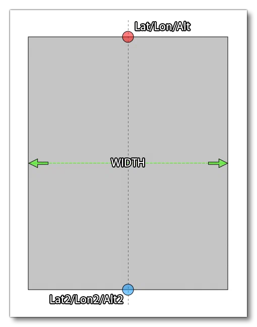
This is a sub-element of <FSData> and is used to define a rectangular surface in a scene. It is generally used for terraforming an area and for changing the surface material within the rectangle. The rectangle is defined by supplying two sets of coordinates for latitude, longitude and altitude, which will set the positions for two sides of the rectangle, while the width value sets how wide the rectangular area will be between those points. The diagram below helps illustrate this:
This element can contain the <RunwayDeformation /> (to apply a slope) as well as the <Heightmap /> (to add deformation) sub-elements, and takes the following attributes:
| Attribute | Description | Type | Required |
|---|---|---|---|
displayName | The display name for the object in the Scenery Editor. NOTE this is only used for ordering in the The Scenery Contents List | String | No |
parentGroupID | The ID of the parent group this object belongs to. NOTE this is only used for ordering in the The Scenery Contents List | Integer | No |
groupIndex | The group index of the object. NOTE this is only used for ordering in the The Scenery Contents List | Integer | No |
width | The total width of the rectangular area, in meters. | Float | Yes |
falloff | Defines the range of terrain affected by the flattening of the rectangular area, higher value meaning an increase range. | Float | Yes |
surface | Material to apply to the rectangular surface. If not supplied, then the original terrain surface material will be used. | No | |
latitude | Latitude of the first side of the rectangular area. | Float | Yes |
longitude | Longitude of the first side of the rectangular area. | Float | Yes |
altitude | Altitude of the first side of the rectangular area, in meters. Please note that the referential for this value is always ELLIPSOID. | Float | Yes |
latitude2 | Latitude of the second side of the rectangular area. | Float | Yes |
longitude2 | Longitude of the second side of the rectangular area. | Float | Yes |
altitude2 | Altitude of the second side of the rectangular area, in meters. Please note that the referential for this value is always ELLIPSOID. | Float | Yes |
priority | This value is used to define the order in which the terraforming rectangles should be applied. | Integer | No |
precision | When set to “TRUE” the modern terrain precision model will be used for heightmaps and terrain changes. WHen set to “FALSE” the legacy terrain precision will be used. | Bool | No |
forceElevation | When enabled (set to “TRUE”) this option will force the ground to be at the same elevation as the terraformer, creating a perfectly flat surface. | Bool | No |
<Heightmap />
This sub-element can be added to a <Rectangle> to define a set of heightmap values to the area being terraformed. This element takes two attributes:
| Attribute | Description | Type | Required |
|---|---|---|---|
width | The width of the data grid. | Integer | Yes |
data | A list of altitude values, where each value is separated by a space, eg:data="49.393673 49.393929 49.394184 49.394440" | String | Yes |
The heightmap will be applied to the entire rectangle, and the attributes are basically defining a grid of values where:
number_of_data_values = width * length
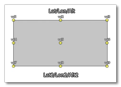
For example, say we want to apply a heightmap of 9 points to the defined rectangle. We’d use this element like this:
<Heightmap width="3" data="val1 val2 val3 val4 val5 val6 val7 val8 val9" />This would then be applied to the rectangle like this:
<Group>
This is a sub-element of <FSData> and is used to define a group of Scenery Objects in the Scenery Editor. It requires one or more <SceneryObject> sub-elements and will be added to the XML automatically by the editor, if required. As such, this element should never be added manually, otherwise errors could occur. This element has the following attributes:
| Attribute | Description | Type | Required |
|---|---|---|---|
name | A unique name for the group. | String | No |
displayName | The display name for the object in the Scenery Editor. NOTE this is only used for ordering in the The Scenery Contents List | String | No |
parentGroupID | The ID of the parent group this object belongs to. NOTE this is only used for ordering in the The Scenery Contents List | Integer | No |
groupIndex | The group index of the object. NOTE this is only used for ordering in the The Scenery Contents List | Integer | No |
groupID | The group ID. | GUID | No |
groupGenerated | Whether the group is auto generated (TRUE) or not (FALSE). | Bool | No |
<DeleteNavigation>
This is a sub-element of <FSData> and is used to define the parts of the Navigation Data to be removed from the scene.
Before editing any navigation data please read the Note On Navigation Data.
This is a self-closing sub-element, with no children, and using the following attributes:
| Attribute | Description | Type | Required |
|---|---|---|---|
deleteAllWaypoints | Delete all waypoints from the world. | Bool | No |
deleteAllVORs | Delete all VOR from the world. | Bool | No |
deleteAllNDBs | Delete all NDB from the world. | Bool | No |
deleteAllTerminalWaypoints | Delete all terminal waypoints from the world. | Bool | No |
deleteAllTerminalNDBs | Delete all terminal NDBs from the world. | Bool | No |
deleteAllILSs | Delete all ILS from the world. | Bool | No |
deleteAllApproaches | Delete all approach legs from the world. | Bool | No |
deleteAllDepartures | Delete all departure waypoints from the world. | Bool | No |
deleteAllArrivals | Delete all arrival waypoints from the world. | Bool | No |
deleteAllFrequencies | Delete all frequencies from the world. | Bool | No |
<LandmarkLocation>
This sub-element of <FSData> is used to designate a particular location as a “landmark”, which will then be shown to the user both in the world map and in the world itself when flying around. It can have the <LandmarkDeparture /> sub-element, or it can be self-closing.
This element can only be used when the parent elements are not part of an airport.
This element has the following attributes:
| Attribute | Description | Type | Required |
|---|---|---|---|
instanceId | GUID used to identify this instance of the element. You can find more information on GUID’s here: GUIDs | String | Yes |
displayName | The display name for the object in the Scenery Editor. NOTE this is only used for ordering in the The Scenery Contents List | String | No |
parentGroupID | The ID of the parent group this object belongs to. NOTE this is only used for ordering in the The Scenery Contents List | Integer | No |
groupIndex | The group index of the object. NOTE this is only used for ordering in the The Scenery Contents List | Integer | No |
lat | The latitude where the landmark appears. | Float | Yes |
lon | The longitude where the landmark appears. | Float | Yes |
alt | The altitude where the landmark appears. | Float | Yes |
name | The name of the landmark. This string can be localised. | String | Yes |
type | The type of landmark object marker to use. One of the following:“City”: This marks a particular city. Landmark cities are only shown on the World Map.“Fauna”: This marks an area of fauna. Landmark fauna areas are shown on the World Map and in the world during a flight.“Natural”: This is for marking some natural phenomenon or area. Landmark natural areas are only shown on the World Map.“POI”: This marks a “Point Of Interest”. Landmark POI are shown on the World Map and in the world during a flight.“Star landmark”: This marks a special landmark with a “Star” marker. Landmark star points are shown on the World Map and in the world during a flight. | String | Yes |
offset | This is an offset for the height of the landmark marker. Normally this is simply left at 0, but if you have multiple landmarks in a similar area, you can use this offset value to ensure that all the markers are seen without any overlap. | Float | No |
owner | The “owner” can be the name of the user that is creating the asset or a company name. | String | No |
distToShowMarker | This sets the distance from the user aircraft outside of which the landmark marker will not be shown, in meters. | Float | No |
altitudeToSpawn | This sets the altitude above the ground at which the user aircraft will be spawned when the POI has been selected from the world map as the departure point. Set to -1 to use the default altitude. Value is in meters. | Float | No |
geoNameId | Integer ID of the record in GeoNames(opens in a new tab) database. | Integer | No |
geoNameFeatureClass | This is the class of geographic feature at the landmark location. It will be used to set world map flags for the feature if included. | String:“A” - Administrative Boundary Features“H” - Hydrographic Features“L” - Area Features“P” - Populated Place Features“R” - Road / Railroad Features“S” - Spot Features“T” - Hypsographic Features“U” - Undersea Features“V” - Vegetation Features | No |
geoNameFeatureCode | This is a 2-5 letter code that refines the feature class down to a specific type of feature. See Landmark Feature Classes for more information. NOTE This is currently not used in the simulation. | String | No |
You can find an example of the generated XML for this object here: LandmarkLocation Objects.
<LandmarkDeparture />
This is an optional sub-element of <LandmarkLocation> used to define the spawn location for any aircraft departing from this landmark location. This element has the following attributes:
| Attribute | Description | Type | Required |
|---|---|---|---|
lat | The latitude where the aircraft will depart. | Float | Yes |
lon | The longitude where the aircraft will depart. | Float | Yes |
alt | The altitude where the aircraft will depart. | Float | Yes |
heading | The heading for the aircraft on departure. | Float | Yes |
<AiracCycle />
This sub-element of <FSData> is used to define the current AIRAC Cycle. It is a self closing element with no sub-elements.
This is generated by the simulation developers and should not be edited. The section here is for information only.
This element has the following attributes:
| Attribute | Description | Type | Required |
|---|---|---|---|
cycleBegin | The date the cycle begins, givens in the following format: “DD-MM-YY”. | String | Yes |
cycleEnd | The date the cycle ends, given in the following format: “DD-MM-YY”. | String | Yes |
cycleNumber | The cycle number, given as a two digit string: “XX”. | String | Yes |
<ProjectedMesh>
This element is used to add a ProjectedMesh Object to a scene, although it can also be used to add a projected mesh object to an airport by adding it as a sub-element of <Airport>. Each projected mesh element requires a <SceneryObject> sub-element to define the object that belongs to it.
The element has the following attributes:
| Attribute | Description | Type | Required |
|---|---|---|---|
displayName | The display name for the object in the Scenery Editor. NOTE this is only used for ordering in the The Scenery Contents List | String | No |
parentGroupID | The ID of the parent group this object belongs to. NOTE this is only used for ordering in the The Scenery Contents List | Integer | No |
groupIndex | The group index of the object. NOTE this is only used for ordering in the The Scenery Contents List | Integer | No |
priority | This option sets the render priority for the projected mesh object. The default render priority is 0, which for most cases is fine. However, if you have overlapping meshes and want one to render over another one, then you will need to change this value to make it a higher or lower priority. Higher priority values will render over lower priorities, for example, a mesh with priority 1 will render over one with priority 0, which in turn will render over one with priority -1. Note that the engine cannot guarantee the render order for meshes with the same priority, so if you need something to always render over or under something else, you need to set this value. | Integer | No |
drawOrder | This option permits you to place meshes into the render hierarchy so that they are drawn under or over different elements. To use this attribute, you must supply one of the given strings, and the projectd mesh will be rendered after the given element has been rendered but before the next element (the element strings are listed in render order). For example, if you select “MARKING”, then the projected mesh will be rendered over Aprons, Taxiways and Runways, but under Markings, Runway Markings and Marking Text. | String (listed in order of rendering):“APRON”“TAXIWAY”“RUNWAY”“MARKING”“RUNWAY_MARKING”“MARKING_TEXT” | No |
surface | This option permits you to select from a list of default surface types that can be applied to the projected mesh. These surfaces will be merged with the mesh texture to add further visual variety and better integrate the mesh with the terrain and surrounding elements. | No | |
groundMerging | Set this attribute to “TRUE” to have the projected mesh object be merged with the underlying ground, or set it to “FALSE” otherwise. You can see a visual example of this effect here: Ground Merging | Boolean | No |
<Tree />
The element has the following attributes:
| Attribute | Description | Type | Required |
|---|---|---|---|
displayName | The display name for the object in the Scenery Editor. NOTE this is only used for ordering in the The Scenery Contents List | String | No |
parentGroupID | The ID of the parent group this object belongs to. NOTE this is only used for ordering in the The Scenery Contents List | Integer | No |
groupIndex | The group index of the object. NOTE this is only used for ordering in the The Scenery Contents List | Integer | No |
specieName | The name of the tree species being placed. There is no set list of species available as it will depend on the packages installed, however you can find a list from the Scenery Editor by checking the Tree Objects. | String | Yes |
modelGUID | The GUID of the tree model to use. | GUID | Yes |
lat | Latitude of the tree object, in degrees between -90.0° and 90.0°. | Float | No |
lon | Longitude of the tree object, in degrees between -180.0° and 180.0°. | Float | No |
altitude | Altitude of the treee object, in ft. | Float | False |
heading | The tree heading, in degrees, used to adjust the tree rotation. | Float | False |
scale | The tree scale, where 1 is the default value. | Float | False |
snapToGround | This option will “snap” the tree to the ground so that - regardless of the terrain height - the element will always be at ground level. | Bool | False |
<VectorPlacement>
This element is for adding in a series of points that will be connected by a vector path and then have a model placed along the path, useful for creating things like fences or power-lines, etc… It can be used as a general scenery element, or within an <Airport> element.
This element requires at least two <Vertex /> sub-elements to define the points between which instances of the given model will be placed, as well as one or more <Model /> sub-elements to define the models that are used.
This element replaces the deprecated <BoundaryFence> and <BlastFence> elements.
The element has the following parameters:
| Attribute | Description | Type | Required |
|---|---|---|---|
displayName | The display name for the object in the Scenery Editor. NOTE this is only used for ordering in the The Scenery Contents List | String | No |
parentGroupID | The ID of the parent group this object belongs to. NOTE this is only used for ordering in the The Scenery Contents List | Integer | No |
groupIndex | The group index of the object. NOTE this is only used for ordering in the The Scenery Contents List | Integer | No |
instanceId | The unique GUID for this instance of the vector placement object. | String | No |
profile | This is the GUID of the model that will be used to populate the vector path. | String | Yes |
snapToVertices | When this attribute is set to “TRUE” the chosen model will only be placed on the single vertices (points) that make up the vector path, instead of being placed along the lengths of the vectors. Default value is “FALSE”. | Bool | No |
spacing | This sets the spacing (in meters) between the models as they are placed along the vector path. This set to a value that brings the object models closer together to keep continuity between them. | Float | Yes |
heading | This attribute can be used to modify the orientation (heading) of the model by a value in degrees. This will be a relative orientation if the rotation attribute is set to “Follow edge” or “Random”, and an absolute orientation if the attribute is “Same”. | Float | Yes |
scale | This attribute is used to scale the model up or down. The base value is 1, and a value less than one will scale it down and a value greater than 1 will scale it up. This will also be cumulative with the scale applied if the scaleDelta option is greater than 0. | Float | Yes |
scaleDelta | This attribute will add a random variation in scale to each model placed along the vector path. The default value is 0, which is no random variation, and any value greater than 0 will be used to apply a random variation in size to each model using the given value as a magnitude for the variation. This variation will be cumulative with the scale setting. | Float | Yes |
rotation | With this attribute you can change the way the model rotation will be handled by the simulation. It can be one of the following strings:"Follow edge": The models will be orientated relative to the direction of the vector path it follows"Same": All the models will be orientated in the same, single direction, which can be edited using the heading parameter."Random": Each model will be given it’s own random orientation regardless of the position it occupies along the vector path. | String | Yes |
avoidDiscontinuity | This attribute can be set to “TRUE” to have the scenery editor try and ensure that the models used match up correctly at the corners of the vector path. If set to “FALSE” then the model may overrun the length of the vectors. | Bool | Yes |
castShadow | If this attribute is set to “TRUE” the models used will cast a shadow, and if set to “FALSE” they won’t. | Bool | No |
forcedAltitude | If this attribute is set to “TRUE”, it will force the vector placement models to be snapped to the altitude of the object, rather than the ground. | Float | No |
<Model />
This sub-element is used to define a model to be used by the parent element object. It can be used in the following object elements:
It is a self-closing element with the following attributes:
| Attribute | Description | Type | Required |
|---|---|---|---|
modelGUID | The unique GUID of the model that is to be used for the vector placement object. | String | Yes |
probability | This is only used when more than one <Model> element has been defined, and sets the probability (between 0 and 1) for the model to be used by the vector placement object. | Float | No |