
Instrument Attachments
This page is currently WIP and will be improved with future updates.
The attachments listed here are all cockpit instruments that can be used in your own aircraft. Most of them can be used in most aircraft, regardless of the career path.
Behavior Parameters
In all of the following instruments, unless otherwise stated, when a model behavior parameter is listed, this is a dynamic parameter that has been created in the SimAttachment model behaviors. For example, the Asobo_Monitoring_FCU has the following in it’s Model XML file (FCU.xml):
<DynamicParameters>
    <CIRCUIT_ID>1</CIRCUIT_ID>
</DynamicParameters>
These dynamic parameters will also need to be listed in the attached_objects.cfg using the behavior_parameter.N parameter. Again, using the previously mentioned FCU attachment, we have this in the attached_objects.cfg:
[SIM_ATTACHMENT.11]
attachment="SimAttachments\Instruments\Asobo_Monitoring_FCU\model\FCU.xml"
attach_to_model="interior"
attach_to_model_minsize=0
attach_to_node="ATTACH_POINT_FCU_01"
attach_offset=0,0,0
attach_pbh=0,0,0
attach_scale=1.0
always_execute_associate_js=1
always_execute_model_behavior=1
vcockpit_parameter.0="VCockpit01_htmlgauge00_params,?Index=1"
alias="FRONT"
behavior_parameter.0="CIRCUIT_ID,'FCU_FES'_n" ;
Here we are defining two parameters, the first is the one the FCU adds in the model behavior, while the second is the name of the circuit that we’ll be supplying to the dynamic parameter. Both of these can now be used in your own model behavior files to control the FCU power.
VCockpit Parameters
In all of the following instruments, unless otherwise stated, when a VCockpit parameter is listed, this is something that can be used in the the attached_objects.cfg using the vcockpit_parameter.N parameter. For example, if we look at the Asobo_MPA_ASD57 there are two additional VCockpit parameters, and these would be listed in the attached_objects.cfg like this:
[SIM_ATTACHMENT.3]
attachment="SimAttachments\Instruments\Asobo_MPA_ASD57\model\ASD57.xml"
attach_to_model="interior"
attach_to_model_minsize=0
attach_to_node="ATTACH_POINT_MFD_AA57_02"
attach_offset=0,0,0
attach_pbh=0,0,0
attach_scale=1.0
always_execute_associate_js=1
always_execute_model_behavior=1
behavior_parameter.0="CIRCUIT_ID,13"
behavior_parameter.1="RADIO_INDEX,2"
behavior_parameter.2="XPDR_INDEX,2"
vcockpit_parameter.0="VCockpit01_htmlgauge00_params,?xpdrIndex=2&radioIndex=2"
It should be noted that almost all instrument attachments have two pre-defined VCockpit parameters created in their panel.cfg file. These are:
[DynamicParameters]
param.0 = "VCockpit01_htmlgauge00_file,[HTML FILE HERE]"
param.1 = "VCockpit01_htmlgauge00_params,"VCockpit01_htmlgauge00_file: This is meant to contain the path to the[instrument].htmlfile. This can potentially be used to look at a different HTML file, but in most cases that should not be necessary and this will not need edited or changed.VCockpit01_htmlgauge00_params: This is meant to contain any additional parameters for the URL. By default this has no additional parameters.
Asobo_Accelerometer_01
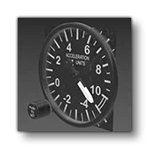
This is a generic accelerometer, used in the DG1001 and E330 in the simulation. This SimAttachment is “plug and play” and does not require any additional setup. Simply add it to the interior of your aircraft and you should have a fully functional basic accelerometer.
Asobo_Accelerometer_02
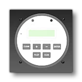
This is an generic digital accelerometer that can be used in any aircraft. Currently it is unused by any of the default aircraft in the simulation, and only has a model, but no code. As such, we do not recommend using this attachment except as a visual asset, however the model is fully finished and you can use tools like the VS Code Extension to find the node names used and create your own behaviours and panel XML if you wish.
Asobo_Accelerometer_03
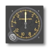
This is a generic accelerometer, used in the E330 in the simulation. This SimAttachment is “plug and play” and does not require any additional setup. Simply add it to the interior of your aircraft and you should have a fully functional basic accelerometer.
Asobo_Accelerometer_03_noknob
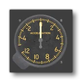
This is a generic accelerometer, used in the DG1001 in the simulation. This SimAttachment is “plug and play” and does not require any additional setup. Simply add it to the interior of your aircraft and you should have a fully functional basic accelerometer.
Asobo_ADF_AS87
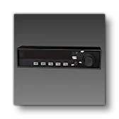
This is an ADF that can be used in any aircraft. For an example, it is currently used by the C172 Classic and the Skyship in the simulation.
Expected behavior parameters and their default values:
<CIRCUIT_ID>1</CIRCUIT_ID>
<ADF_ID>1</ADF_ID>CIRCUIT_ID: Contains the index of the circuit to use to verify that the ADF is powered. The name of the circuit can be used if using the'Name'_nsyntax.ADF_ID: contains the index of the ADF channel used (1 or 2).
This is not a VCockpit, and as such does not support any VCockpit parameters or panel.xml values.
Asobo_ADF_BearingIndicator_01
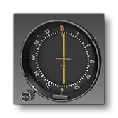
This is a generic bearing indicator (ADF), used in the C172 Classic and Skyship in the simulation. This SimAttachment is “plug and play” and does not require any additional setup. Simply add it to the interior of your aircraft and you should have a fully functional basic ADF.
Asobo_Airspeed_01
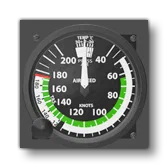
Coming Soon.
Asobo_Airspeed_02
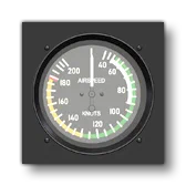
Coming Soon.
Asobo_Altimeter_01
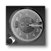
This is a generic altimeter that can be used in any aircraft. For an example, it is currently used by the AT802, the Cabri G2, the Skyship, and may other aircraft in the simulation.
Expected behavior parameter and its default value:
<ALTIMETER_ID>0</ALTIMETER_ID>ALTIMETER_ID: Defines the is the altimeter ID to be used by this gauge. If two altimeters share the same altimeter ID, they will be synced.
This is not a VCockpit, and as such does not support any VCockpit parameters or panel.xml values.
Asobo_Altimeter_02
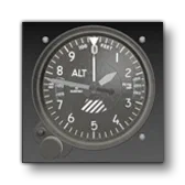
Coming Soon.
Asobo_Altimeter_03
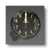
Coming Soon.
Asobo_Altimeter_4FGH10
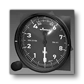
This is an altimeter that can be used in any aircraft. For an example, it is currently used by the DG 1001 in the simulation.
Expected behavior parameter and its default value:
<ALTIMETER_ID>0</ALTIMETER_ID>ALTIMETER_ID: Defines the is the altimeter ID to be used by this gauge. If two altimeters share the same altimeter ID, they will be synced.
This is not a VCockpit, and as such does not support any VCockpit parameters or panel.xml values.
Asobo_Ammeter_01
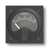
This is a generic analog ammeter, used in the 208B and Skyship in the simulation. This SimAttachment is “plug and play” and does not require any additional setup. Simply add it to the interior of your aircraft and you should have a fully functional basic ammeter.
Asobo_Attitude_Indicator_01
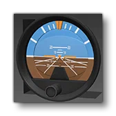
This is a generic attitude indicator, used in the 208B and Skyship in the simulation. This SimAttachment is “plug and play” and does not require any additional setup. Simply add it to the interior of your aircraft and you should have a fully functional basic attitude indicator.
Asobo_Attitude_Indicator_02

This is a generic attitude indicator, used in the Cabri G2 in the simulation. This SimAttachment is “plug and play” and does not require any additional setup. Simply add it to the interior of your aircraft and you should have a fully functional basic attitude indicator.
Asobo_Attitude_Indicator_03
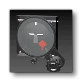
Coming Soon.
Asobo_Attitude_Indicator_04
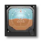
Coming Soon.
Asobo_Attitude_Indicator_05
Coming Soon.
Asobo_Attitude_Indicator_06
Coming soon.
Asobo_Attitude_Indicator_AS2610

Coming soon.
Asobo_Attitude_Indicator_AS321

This is an attitude indicator that can be used in any aircraft. For an example, it is currently used by the H125 in the simulation.
Expected behavior parameter and its default value:
<CIRCUIT_ID>0</CIRCUIT_ID>CIRCUIT_ID: Contains the index of the circuit to use to verify that the indicator is powered. The name of the circuit can be used if using the'Name'_nsyntax.
This is not a VCockpit, and as such does not support any VCockpit parameters or panel.xml values.
Asobo_Attitude_Indicator_G5

This is an attitude indicator that can be used in any aircraft.
Expected behavior parameter and its default value:
<CIRCUIT_ID>0</CIRCUIT_ID>
<ID>1</ID>CIRCUIT_ID: Contains the index of the circuit to use to verify that the indicator is powered. The name of the circuit can be used if using the'Name'_nsyntax.ID: Contains the index of the G5 to use. This is used to support multiple G5s, each with their own ID (between 1 and 3 only).
This is not a VCockpit, and as such does not support any VCockpit parameters or panel.xml values.
Asobo_AudioPanel_01
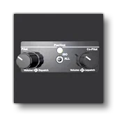
This is an generic audio panel that can be used in any aircraft. Currently it is unused by any of the default aircraft in the simulation, and only has a model, but no code. As such, we do not recommend using this attachment except as a visual asset, however the model is fully finished and you can use tools like the VS Code Extension to find the node names used and create your own behaviours and panel XML if you wish.
Asobo_AudioPanel_02
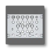
This is a generic audio panel that can be used in any aircraft. Currently it is unused by any of the default aircraft in the simulation, and only has a model, but no code. As such, we do not recommend using this attachment except as a visual asset, however the model is fully finished and you can use tools like the VS Code Extension to find the node names used and create your own behaviours and panel XML if you wish.
Asobo_AudioPanel_03
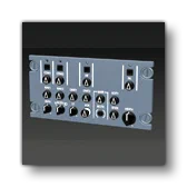
This is a generic audio panel that can be used in any aircraft. Currently it is unused by any of the default aircraft in the simulation, and only has a model, but no code. As such, we do not recommend using this attachment except as a visual asset, however the model is fully finished and you can use tools like the VS Code Extension to find the node names used and create your own behaviours and panel XML if you wish.
Asobo_AudioPanel_AS28
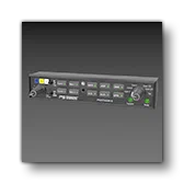
Coming soon.
Asobo_AUDIOPANEL_AS340
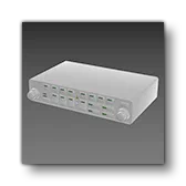
This is a generic audio panel that can be used in any aircraft. Currently it is unused by any of the default aircraft in the simulation, and only has a model, but no code. As such, we do not recommend using this attachment except as a visual asset, however the model is fully finished and you can use tools like the VS Code Extension to find the node names used and create your own behaviours and panel XML if you wish.
Asobo_AudioPanel_G350
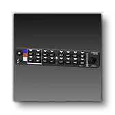
This is an audio panel that can be used in any aircraft. For an example, it is currently used by the H125 in the simulation.
Expected behavior parameters and their default values:
<CIRCUIT_ID>1</CIRCUIT_ID>
<EMISSIVE_INTENSITY>1</EMISSIVE_INTENSITY>CIRCUIT_ID: Contains the index of the circuit to use to verify that the panel is powered. The name of the circuit can be used if using the'Name'_nsyntax.EMISSIVE_INTENSITY: Contains a factor that can be used to affect the intensity of the decals emissives..
This is not a VCockpit, and as such does not support any VCockpit parameters or panel.xml values.
Asobo_AUTOPILOT_AS50
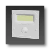
This is an generic autopilot panel that can be used in any aircraft. Currently it is unused by any of the default aircraft in the simulation, and only has a model, but no code. As such, we do not recommend using this attachment except as a visual asset, however the model is fully finished and you can use tools like the VS Code Extension to find the node names used and create your own behaviours and panel XML if you wish.
Asobo_Autopilot_AS65
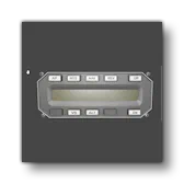
This is an generic autopilot panel that can be used in any aircraft. Currently it is unused by any of the default aircraft in the simulation, and only has a model, but no code. As such, we do not recommend using this attachment except as a visual asset, however the model is fully finished and you can use tools like the VS Code Extension to find the node names used and create your own behaviours and panel XML if you wish.
Asobo_Autopilot_AS140
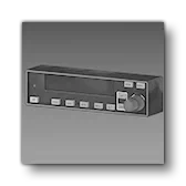
This is an autopilot panel that can be used in any aircraft. It is not currently used in any aircraft in the simulation
Expected behavior parameters and their default values:
<SCREEN_EMISSIVE_CODE>1</SCREEN_EMISSIVE_CODE>
<BUTTON_EMISSIVE_FACTOR>0.2</BUTTON_EMISSIVE_FACTOR>SCREEN_EMISSIVE_CODE: This can be used to override the default logic of the emissive of the screen. If not set, the default logic will automatically tune the brightness to 1.BUTTON_EMISSIVE_FACTOR: Contains a factor that can be used to affect the intensity of the emissives used by the buttons.
This is not a VCockpit, and as such does not support any VCockpit parameters or panel.xml values.
Asobo_Autopilot_G305
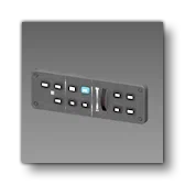
This is an generic autopilot panel that can be used in any aircraft. Currently it is unused by any of the default aircraft in the simulation, and only has a model, but no code. As such, we do not recommend using this attachment except as a visual asset, however the model is fully finished and you can use tools like the VS Code Extension to find the node names used and create your own behaviours and panel XML if you wish.
Asobo_Autopilot_G307_NoYawDamper
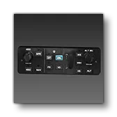
This is a main autopilot panel that can be used in any aircraft. For an example, it is currently used by the X-Cub in the simulation.
Expected behavior parameters and their default values:
<CIRCUIT_ID>1</CIRCUIT_ID>
<POTENTIOMETER>1</POTENTIOMETER>CIRCUIT_ID: Contains the index of the circuit to use to verify that the decal emissives are powered. The name of the circuit can be used if using the'Name'_nsyntax. Note that if the circuit ID is ommited (ie: you use a self closing<CIRCUIT_ID />for the element), then the panel will checkCIRCUIT GENERAL PANEL ONfor power verification.POTENTIOMETER: Contains the index of the potentiometer to use for the decal brightness.
This is not a VCockpit, and as such does not support any VCockpit parameters or panel.xml values.
Asobo_Autopilot_G307_YawDamper
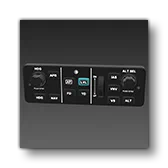
This is a a main autopilot panel that can be used in any aircraft. Currently this asset is visual only and contains no behaviors or panel setup. However the model is fully finished and you can use tools like the VS Code Extension to find the node names used and create your own behaviours and panel XML if you wish.
Asobo_Autopilot_G700
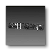
This is a main autopilot panel that can be used in any aircraft. For an example, it is currently used by the 208B in the simulation.
Expected behavior parameters and their default values:
<CIRCUIT_ID>1</CIRCUIT_ID>CIRCUIT_ID: Contains the index of the circuit to use to verify that the decal emissives are powered. The name of the circuit can be used if using the'Name'_nsyntax.
This is not a VCockpit, and as such does not support any VCockpit parameters or panel.xml values.
Asobo_CDI_With_Glide_01
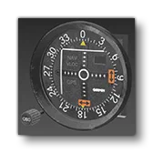
This is an analogue course deviation indicator - with glide-slop indication - that can be used in any aircraft. For an example, it is currently used by the C172 Classic and the Cabri G2 in the simulation.
Expected behavior parameters and their default values:
<NAV_ID>1</NAV_ID>NAV_ID: Contains the nav channel used by the instrument.
This is not a VCockpit, and as such does not support any VCockpit parameters or panel.xml values.
Asobo_CDI_Without_Glide_01
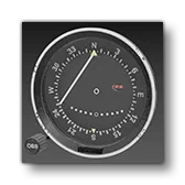
This is an analogue course deviation indicator (with no glide slope indication) that can be used in any aircraft. This is currently not used in any of the default aircraft in the simulation.
Expected behavior parameters and their default values:
<NAV_ID>1</NAV_ID>NAV_ID: Contains the nav channel used by the instrument.
This is not a VCockpit, and as such does not support any VCockpit parameters or panel.xml values.
Asobo_Clock_Analogic_01
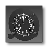
This is an analogue clock that can be used in any aircraft. Currently it is unused by any of the default aircraft in the simulation, and only has a model, but no code. As such, we do not recommend using this attachment except as a visual asset, however the model is fully finished and you can use tools like the VS Code Extension to find the node names used and create your own behaviours and panel XML if you wish.
Asobo_Clock_Analogic_02
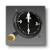
Coming Soon.
Asobo_Clock_AS803
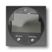
Coming Soon.
Asobo_Clock_Digital_01
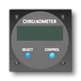
This is a digital clock that can be used in any aircraft. Currently it is unused by any of the default aircraft in the simulation, and only has a model, but no code. As such, we do not recommend using this attachment except as a visual asset, however the model is fully finished and you can use tools like the VS Code Extension to find the node names used and create your own behaviours and panel XML if you wish.
Asobo_COM_T92
Coming soon.
Asobo_COMNAV_AS155
This is a communication and navigation panel that can be used in any aircraft. Currently it is unused by any of the default aircraft in the simulation. This SimAttachment is “plug and play” and does not require any additional setup. Simply add it to the interior of your aircraft and you should have a fully functional basic ComNav.
Asobo_COMNAV_AS196
This is a communication and navigation panel that can be used in any aircraft. Currently it is unused by any of the default aircraft in the simulation, and only has a model, but no code. As such, we do not recommend using this attachment except as a visual asset, however the model is fully finished and you can use tools like the VS Code Extension to find the node names used and create your own behaviours and panel XML if you wish.
Asobo_COMNAV_B787
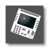
This is a communication and navigation panel that can be used in any aircraft. Currently it is unused by any of the default aircraft in the simulation, and only has a model, but no code. As such, we do not recommend using this attachment except as a visual asset, however the model is fully finished and you can use tools like the VS Code Extension to find the node names used and create your own behaviours and panel XML if you wish.
Asobo_Compass_01

This is a generic analogue compass. This SimAttachment is “plug and play” and does not require any additional setup. Simply add it to the interior of your aircraft and you should have a fully functional basic compass.
Asobo_Compass_02
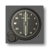
Coming Soon.
Asobo_Compass_AS2300
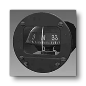
This is a generic analogue compass. For an example, it is currently used by the AT 802 and the DG 1001 in the simulation. This SimAttachment is “plug and play” and does not require any additional setup. Simply add it to the interior of your aircraft and you should have a fully functional basic compass.
Asobo_ELT_01
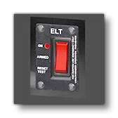
Coming soon.
Asobo_FMC_B737
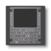
This is a generic flight management computer that can be used in any aircraft. Currently it is unused by any of the default aircraft in the simulation, and only has a model, but no code. As such, we do not recommend using this attachment except as a visual asset, however the model is fully finished and you can use tools like the VS Code Extension to find the node names used and create your own behaviours and panel XML if you wish.
Asobo_FMC_B787
This is a generic flight model computer and is not currently used by any aircraft in the simulation. This SimAttachment is “plug and play” and does not require any additional setup. Simply add it to the interior of your aircraft and you should have a fully functional basic FMC.
Asobo_FMC_CJ4
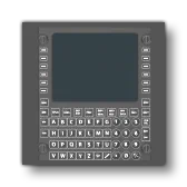
This is a generic flight model computer and is not currently used by any aircraft in the simulation. This SimAttachment is “plug and play” and does not require any additional setup. Simply add it to the interior of your aircraft and you should have a fully functional basic FMC.
Asobo_FMC_Frame_Black
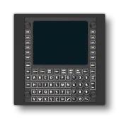
This is a generic flight model computer and is not currently used by any aircraft in the simulation. This SimAttachment is “plug and play” and does not require any additional setup. Simply add it to the interior of your aircraft and you should have a fully functional basic compass.
Asobo_FMC_Frame_Grey
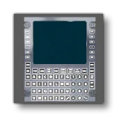
This is a generic flight model computer and is not currently used by any aircraft in the simulation. This SimAttachment is “plug and play” and does not require any additional setup. Simply add it to the interior of your aircraft and you should have a fully functional basic FMC.
Asobo_Fuel_Digital_01
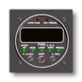
This is a generic digital fuel gauge that can be used in any aircraft. Currently it is unused by any of the default aircraft in the simulation, and only has a model, but no code. As such, we do not recommend using this attachment except as a visual asset, however the model is fully finished and you can use tools like the VS Code Extension to find the node names used and create your own behaviours and panel XML if you wish.
Asobo_Fuel_Digital_02
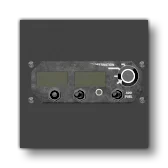
This is a generic digital fuel display and is not currently used by any aircraft in the simulation. This SimAttachment is “plug and play” and does not require any additional setup. Simply add it to the interior of your aircraft and you should have a fully functional basic fuel display.
Asobo_Fuel_Gauge_Double_01
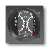
This is an analogue fuel level indicator that can be used in any aircraft. For an example, it is currently used by the C172 Classic in the simulation.
Expected behavior parameters and their default values:
<TANK_ID_1>1</TANK_ID_1>
<TANK_ID_2>1</TANK_ID_2>TANK_ID_1: Contains the index of the first tank to get the fuel level from. The name of the tank can be used if using the'Name'_nsyntax.TANK_ID_2: Contains the index of the second tank to get the fuel level from. The name of the tank can be used if using the'Name'_nsyntax.
This is not a VCockpit, and as such does not support any VCockpit parameters or panel.xml values.
Asobo_FuelFlow_EGT_01
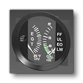
This is an analogue fuel flow and exhaust gas indicator that can be used in any aircraft. For an example, it is currently used by the C172 Classic in the simulation.
Expected behavior parameters and their default values:
<MIN_VALUE_EGT>1250</MIN_VALUE_EGT>
<MAX_VALUE_EGT>1650</MAX_VALUE_EGT>MIN_VALUE_EGT: should be the EGT (in Fahrenheit) for the lowest needle position.MAX_VALUE_EGT: should be the EGT (Fahrenheit) for the highest needle position.- NOTE: these Min/Max are generally not dynamic parameters, as they are often written directly on the gauge which means that these bounds will not be able to change. This is not the case here as the only indication is 25 F DIV which gives you the total range between min and max (16 25F divisions = 400F), but not that min and max.
This is not a VCockpit, and as such does not support any VCockpit parameters or panel.xml values.
Asobo_Garmin_Common
This sim attachment is a “special” case within the included attachments. It is not designed to be attached directly within an aircraft, but is instead simply a collection of textures and model behavior files that are used by other attachments. As such, they should not be used, unless you are setting things up to use them as part of another Sim Attachment.
Asobo_GPS_G96
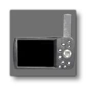
Coming Soon.
Asobo_GPS_G196
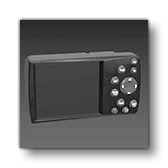
This is a GPS screen that can be used in any aircraft. Currently it is unused by any of the default aircraft in the simulation, and only has a model, but no code. As such, we do not recommend using this attachment except as a visual asset, however the model is fully finished and you can use tools like the VS Code Extension to find the node names used and create your own behaviours and panel XML if you wish.
Asobo_Heading_Indicator_01
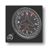
This is a main autopilot panel that can be used in any aircraft. For an example, it is currently used by the AT 802 and Cabr iG2 in the simulation.
Expected behavior parameters and their default values:
<HEADING_ID>1</HEADING_ID>HEADING_ID: Contains the index of the heading indicator used. Multiple Heading indicators sharing the same ID value will be syncronized.
This is not a VCockpit, and as such does not support any VCockpit parameters or panel.xml values.
Asobo_Heading_Indicator_Two_Knobs
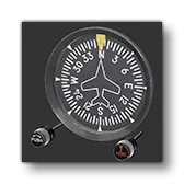
This is a generic heading indicator. This SimAttachment is “plug and play” and does not require any additional setup. Simply add it to the interior of your aircraft and you should have a fully functional basic indicator.
Asobo_Hourmeter_01
This is a generic heading indicator. This SimAttachment is “plug and play” and does not require any additional setup. Simply add it to the interior of your aircraft and you should have a fully functional basic indicator.
Asobo_Hourmeter_02
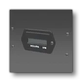
Coming Soon.
Asobo_HSI_01
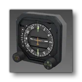
This is an HSI that can be used in any aircraft. It is currently not used by any of the default aircraft in the simulation.
Expected behavior parameter and its default value:
<NAV_ID>1</NAV_ID>NAV_ID: contains the index of the NAV channel used (1 to 3).
This is not a VCockpit, and as such does not support any VCockpit parameters or panel.xml values.
Asobo_HSI_AS525
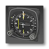
This is an analogue HSI indicator that can be used in any aircraft. For an example, it is currently used by the H125 in the simulation.
Expected behavior parameters and their default values:
<CIRCUIT_ID>1</CIRCUIT_ID>
<NAV_ID1>1</NAV_ID1>
<NAV_ID2>2</NAV_ID2>CIRCUIT_ID: Contains the index of the circuit to use to verify that the indicator is powered. The name of the circuit can be used if using the'Name'_nsyntax.NAV_ID1: Contains contain the ID of the first NAV channel used by the gauge.NAV_ID2: Contains contain the ID of the second NAV channel used by the gauge.
This is not a VCockpit, and as such does not support any VCockpit parameters or panel.xml values.
Asobo_HSI_Digital_01
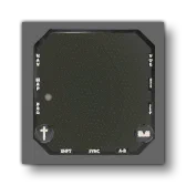
Coming Soon.
Asobo_Lever_BannerRelease

Coming Soon.
Asobo_Lever_LandingGearFloats_Box
Coming Soon.
Asobo_Lever_LandingGearFloats_Round
Coming Soon.
Asobo_Lever_LandingGearSafetyPump

Coming Soon.
Asobo_Lever_LandingGearSkis_Box
Coming Soon.
Asobo_Lever_WaterRudder
Coming Soon.
Asobo_Light_NavStrobe_Left_01

Coming Soon.
Asobo_Light_NavStrobe_Right_01

Coming Soon.
Asobo_Magneto_L_R_Both

Coming Soon.
Asobo_MFD_LX8030
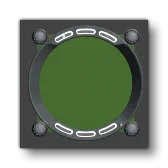
Coming Soon.
Asobo_Monitoring_AS_50T

This is a main display panel that can be used in any aircraft. For an example, it is currently used by the AT 802 in the simulation.
Expected behavior parameters and their default values:
<CIRCUIT_ID>1</CIRCUIT_ID>
<BOUNCE_POTENTIOMETER>1</BOUNCE_POTENTIOMETER>CIRCUIT_ID: Contains the index of the circuit to use to verify that the panel is powered. The name of the circuit can be used if using the'Name'_nsyntax.BOUNCE_POTENTIOMETER: Contains the index of the potentiometer to use for the brightness of the screen (the brightness will be written within the potentiometer which can then be used within the lights definition).
The supported VCockpit parameters are the standard ones:
VCockpit01_htmlgauge00_file, Generic/Monitoring/MVP50/mvp50.htmlVCockpit01_htmlgauge00_params: This is empty by default.
Asobo_Monitoring_AS900

Coming Soon.
Asobo_Monitoring_ASD10
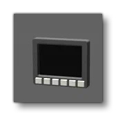
Coming Soon.
Asobo_Monitoring_ASMiniVigilus

This is a “mini” version of the Vigilus monitoring screen that can be used in any aircraft. Currently it is unused by any of the default aircraft in the simulation, and only has a model, but no code. As such, we do not recommend using this attachment except as a visual asset.
Asobo_Monitoring_ASVigilus

This is a Vigilus monitoring screen that can be used in any aircraft. Currently it is unused by any of the default aircraft in the simulation.
Expected behavior parameter and its default value:
<CIRCUIT_ID>39</CIRCUIT_ID>CIRCUIT_ID: Contains the index of the circuit to use to verify that the panel is powered. The name of the circuit can be used if using the'Name'_nsyntax.
The supported VCockpit parameters are the standard ones:
VCockpit01_htmlgauge00_file, Generic/Monitoring/ASVigilus/ASVigilus.htmlVCockpit01_htmlgauge00_params: This is empty by default.
Asobo_Monitoring_FCU
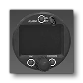
This is a generic Flight Control Unit that can be used in any aircraft. For an example, it is currently used by the DG 1001 in the simulation.
Expected behavior parameter and its default value:
<CIRCUIT_ID>1</CIRCUIT_ID>CIRCUIT_ID: Contains the index of the circuit to use to verify that the panel is powered. The name of the circuit can be used if using the'Name'_nsyntax.
The supported VCockpit parameters are the standard ones:
VCockpit01_htmlgauge00_file, Generic/Monitoring/FES-FCU/FES-FCU.htmlVCockpit01_htmlgauge00_params: This is empty by default.
Asobo_Monitoring_GenericSquare
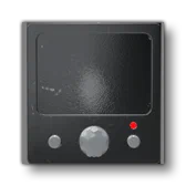
Coming Soon.
Asobo_Monitoring_OilTemp_Press_01
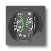
This is a generic analogue gauge for monitoring the oil temperature and pressure. For an example, it is currently used by the C172 Classic in the simulation. This SimAttachment is “plug and play” and does not require any additional setup.
Asobo_Monitoring_Temperature_ASTM1R

Coming Soon.
Asobo_Monitoring_Vaccum_Amp_01
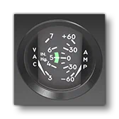
This is a generic analogue vacuum and ampmeter indicator. For an example, it is currently used by the C172 Classic in the simulation.
Expected behavior parameter and its default value:
<BATTERY_ID>1</BATTERY_ID>BATTERY_ID: Contains the index of the battery to use. The name of the battery can be used if using the'Name'_nsyntax.
This is not a VCockpit, and as such does not support any VCockpit parameters or panel.xml values.
Asobo_MPA_Aera
Coming Soon.
Asobo_MPA_AS_XL

This is small information display for use in hot air balloons. For an example, it is currently used by the FlyDoo in the simulation.
This attachment neither defines nor requires any additional behavior parameters.
The supported VCockpit parameters are the standard ones:
VCockpit01_htmlgauge00_file, HotAirBalloon/Syride/Syride.htmlVCockpit01_htmlgauge00_params: This is empty by default.
Asobo_MPA_ASD57
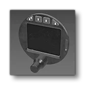
This is the ASD57 radio/transponder that can be used in any aircraft. For an example, it is currently used by the DG 1001 in the simulation.
Expected behavior parameters and their default values:
<CIRCUIT_ID>1</CIRCUIT_ID>
<RADIO_INDEX>1</RADIO_INDEX>
<XPDR_INDEX>1</XPDR_INDEX>CIRCUIT_ID: Contains the index of the circuit to use to verify that the panel is powered. The name of the circuit can be used if using the'Name'_nsyntax.RADIO_INDEX: Contains the index of the radio. It is used to identify which radio index should be used when using functions related to COM frequencies. It has to match the VCockpit parameter, explained below.XPDR_INDEX: Contains the index of the transponder. It is used to identify which transponder index should be used when using functions related to transponder frequencies. It has to match the VCockpit parameter, explained below.
The supported VCockpit parameters are the standard ones:
VCockpit01_htmlgauge00_file, Generic/Radios/ASD57/ASD57.htmlVCockpit01_htmlgauge00_params: This is empty by default but will require the following parameter definitions in the attached_objects.cfg (see VCockpit Parameters, above, for more information).radioIndex- This allows you to specify the radio index, which can be necessary if you want multiple instances of this panel running with separate radios.xpdrIndex- This allows you to specify the transponder index, which can be necessary if you want multiple instances of this panel running with separate transponders.
Asobo_MPA_ASEvo
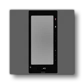
Coming Soon.
Asobo_MPA_ASX9000
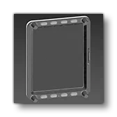
This is a a main display panel that can be used in any aircraft. Currently this asset is visual only and contains no behaviors or panel setup. However the model is fully finished and you can use tools like the VS Code Extension to find the node names used and create your own behaviours and panel XML if you wish.
Asobo_MPA_ASX9070
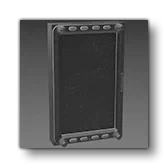
This is a a main display panel that can be used in any aircraft. For an example, it is currently used by the DG 1001 in the simulation.
Expected behavior parameters and their default values:
<CIRCUIT_ID>1</CIRCUIT_ID>
<BOUNCE_POTENTIOMETER>1</BOUNCE_POTENTIOMETER>CIRCUIT_ID: Contains the index of the circuit to use to verify that the panel is powered. The name of the circuit can be used if using the'Name'_nsyntax.BOUNCE_POTENTIOMETER: Contains the index of the potentiometer to use for the brightness of the screen (the brightness will be written within the potentiometer which can then be used within the lights definition).
The supported VCockpit parameters are the standard ones:
VCockpit01_htmlgauge00_file, Generic/Radios/ASD57/ASD57.htmlVCockpit01_htmlgauge00_params: This is empty by default.
Asobo_MPA_CJ4
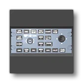
Coming Soon.
Asobo_MPA_G3X_Mini
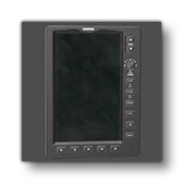
This is a “mini” version of the Garmin G3X display that can be used in any aircraft. For an example, it is currently used by the Extra 330LT in the simulation.
Expected behavior parameters and their default values:
CIRCUIT_ID>1</CIRCUIT_ID>
<POTENTIOMETER>1</POTENTIOMETER>
<BOUNCE_POTENTIOMETER>1</BOUNCE_POTENTIOMETER>
<HTML_EVENT_ID>1</HTML_EVENT_ID>CIRCUIT_ID: Contains the index of the circuit to use to verify that the panel is powered. The name of the circuit can be used if using the'Name'_nsyntax.POTENTIOMETER: Contains the index of the potentiometer to use for the brightness of the emissive component of the decals.BOUNCE_POTENTIOMETER: Contains the index of the potentiometer to use for the brightness of the screen (the brightness will be written within the potentiometer which can then be used within the lights definition).HTML_EVENT_ID: Contains the index of this instance of the G3X mini. It can be used when there are multiples instances of the G3X to to ensure that interacting with one doesn’t interact with the other. It must match with theIndexin the VCockpit parameters.
The supported VCockpit parameters are the standard ones:
VCockpit01_htmlgauge00_file, NavSystems/G3XTouchv2/G3XTouch.htmlVCockpit01_htmlgauge00_params: This is empty by default but will require the following parameter definition in the attached_objects.cfg (see VCockpit Parameters, above, for more information).Index- This allows you to specify a unique index for the display, allowing you to differentiate between multiple instances of the G3X mini (if there are more than 1), which can be use to separate their brightness levels. Must match the value given in the<HTML_EVENT_ID>behavior parameter.
For more information and additional setup details please see the following page on the MSFS Avionics Framework website:
Asobo_MPA_G3X_Touch
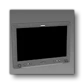
This is a Garmin G3X Touch display that can be used in any aircraft. For an example, it is currently used by the CubCrafters X Cub in the simulation.
Expected behavior parameters and their default values:
<CIRCUIT_ID>1</CIRCUIT_ID>
<BOUNCE_POTENTIOMETER>1</BOUNCE_POTENTIOMETER>
<BACKLIGHT_ID>1</BACKLIGHT_ID>CIRCUIT_ID: Contains the index of the circuit to use to verify that the panel is powered. The name of the circuit can be used if using the'Name'_nsyntax.BOUNCE_POTENTIOMETER: Contains the index of the potentiometer to use for the brightness of the screen (the brightness will be written within the potentiometer which can then be used within the lights definition).BACKLIGHT_ID: Contains the index of this instance of the G3X. It can be used when there are multiples instances of the G3X to control their backlighting separately. It must match with theIndexin the VCockpit parameters.
The supported VCockpit parameters are the standard ones:
VCockpit01_htmlgauge00_file, NavSystems/G3XTouchv2/G3XTouch.htmlVCockpit01_htmlgauge00_params: This is empty by default but will require the following parameter definition in the attached_objects.cfg (see VCockpit Parameters, above, for more information).Index- This allows you to specify a unique index for the display, allowing you to differentiate between multiple instances of the G3X (if there are more than 1), which can be use to separate their brightness levels. Must match the value given in the<BACKLIGHT_ID>behavior parameter.
For more information and additional setup details please see the following page on the MSFS Avionics Framework website:
Asobo_MPA_G1000_AudioPanel
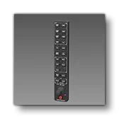
This is an audio panel that is meant to be used in conjunction with one of the Garmin G1000 displays. For an example, it is currently used by the Cessna 172 Skyhawk and other default aircraft in the simulation.
Expected behavior parameters and their default values:
<POTENTIOMETER>1</POTENTIOMETER>
<CIRCUIT_ID>1</CIRCUIT_ID>POTENTIOMETER: Contains the index of the potentiometer to use for the brightness of the emissive component of the decals.CIRCUIT_ID: Contains the index of the circuit to use to verify that the panel is powered. The name of the circuit can be used if using the'Name'_nsyntax.
The supported VCockpit parameters are the standard ones:
VCockpit01_htmlgauge00_file, NavSystems/WTG1000v2/PFD/WTG1000_PFD.htmlVCockpit01_htmlgauge00_params: This is empty by default.
Asobo_MPA_G1000_Autopilot_NoYawDamper

This is a version of the Garmin G1000 display - with an autopilot panel and no yaw damper button - that can be used in any aircraft. For an example, it is currently used by the Cessna 172 Skyhawk in the simulation.
Expected behavior parameters and their default values:
<POTENTIOMETER>1</POTENTIOMETER>
<AMBIENT_POTENTIOMETER>1</AMBIENT_POTENTIOMETER>
<CIRCUIT_ID>1</CIRCUIT_ID>
<ALTITUDE_ID>0</ALTITUDE_ID>
<ADDITIONAL_EMISSIVE_FACTOR>1</ADDITIONAL_EMISSIVE_FACTOR>POTENTIOMETER: Contains the index of the potentiometer to use for the brightness of the emissive component of the decals.AMBIENT_POTENTIOMETER: Contains the index of the potentiometer to use for the brightness of the screen (the brightness will be written within the potentiometer which can then be used within the lights definition).CIRCUIT_ID: Contains the index of the circuit to use to verify that the panel is powered. The name of the circuit can be used if using the'Name'_nsyntax.ALTITUDE_ID: Contains the index of the panel altimeter, allowing you to have multiple G1000 (or other altimeters) with their separate settings.ADDITIONAL_EMISSIVE_FACTOR: Can contain some custom calculation that will affect both the screen and the emissive decal brightness. The default value of 1 means it doesn’t change the calculated value.
The supported VCockpit parameters are the standard ones:
VCockpit01_htmlgauge00_file, NavSystems/WTG1000v2/PFD/WTG1000_PFD.htmlVCockpit01_htmlgauge00_params: This is empty by default.
For more information and additional setup details please see the following page on the MSFS Avionics Framework website:
Asobo_MPA_G1000_Autopilot_YawDamper

This is a version of the Garmin G1000 display - with an autopilot panel and a yaw damper button - that can be used in any aircraft. For an example, it is currently used by the DA62 in the simulation.
Expected behavior parameters and their default values:
<POTENTIOMETER>1</POTENTIOMETER>
<AMBIENT_POTENTIOMETER>1</AMBIENT_POTENTIOMETER>
<CIRCUIT_ID>1</CIRCUIT_ID>
<ALTITUDE_ID>0</ALTITUDE_ID>
<ADDITIONAL_EMISSIVE_FACTOR>1</ADDITIONAL_EMISSIVE_FACTOR>POTENTIOMETER: Contains the index of the potentiometer to use for the brightness of the emissive component of the decals.AMBIENT_POTENTIOMETER: Contains the index of the potentiometer to use for the brightness of the screen (the brightness will be written within the potentiometer which can then be used within the lights definition).CIRCUIT_ID: Contains the index of the circuit to use to verify that the panel is powered. The name of the circuit can be used if using the'Name'_nsyntax.ALTITUDE_ID: Contains the index of the panel altimeter, allowing you to have multiple G1000 (or other altimeters) with their separate settings.ADDITIONAL_EMISSIVE_FACTOR: Can contain some custom calculation that will affect both the screen and the emissive decal brightness. The default value of 1 means it doesn’t change the calculated value.
The supported VCockpit parameters are the standard ones:
VCockpit01_htmlgauge00_file, NavSystems/WTG1000v2/PFD/WTG1000_PFD.htmlVCockpit01_htmlgauge00_params: This is empty by default.
For more information and additional setup details please see the following page on the MSFS Avionics Framework website:
Asobo_MPA_G1000_ControlPad
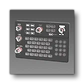
Coming Soon.
Asobo_MPA_G1000_NoAutopilot
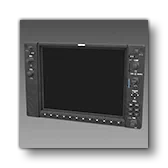
This is a version of the Garmin G1000 display - with no autopilot panel - that can be used in any aircraft. This panel is currently not used by any default aircraft in the simulation.
Expected behavior parameters and their default values:
<POTENTIOMETER>1</POTENTIOMETER>
<AMBIENT_POTENTIOMETER>1</AMBIENT_POTENTIOMETER>
<CIRCUIT_ID>1</CIRCUIT_ID>
<ADDITIONAL_EMISSIVE_FACTOR>1</ADDITIONAL_EMISSIVE_FACTOR>POTENTIOMETER: Contains the index of the potentiometer to use for the brightness of the emissive component of the decals.AMBIENT_POTENTIOMETER: Contains the index of the potentiometer to use for the brightness of the screen (the brightness will be written within the potentiometer which can then be used within the lights definition).CIRCUIT_ID: Contains the index of the circuit to use to verify that the panel is powered. The name of the circuit can be used if using the'Name'_nsyntax.ADDITIONAL_EMISSIVE_FACTOR: Can contain some custom calculation that will affect both the screen and the emissive decal brightness. The default value of 1 means it doesn’t change the calculated value.
The supported VCockpit parameters are the standard ones:
VCockpit01_htmlgauge00_file, NavSystems/WTG1000v2/PFD/WTG1000_PFD.htmlVCockpit01_htmlgauge00_params: This is empty by default.
For more information and additional setup details please see the following page on the MSFS Avionics Framework website:
Asobo_MPA_G1000_NoAutopilot_Alt_Hdg_Knobs

This is a version of the Garmin G1000 display - without an autopilot panel but with altitude and heading knobs - that can be used in any aircraft. For an example, it is currently used by the Cessna 172 Skyhawk in the simulation.
Expected behavior parameters and their default values:
<POTENTIOMETER>1</POTENTIOMETER>
<AMBIENT_POTENTIOMETER>1</AMBIENT_POTENTIOMETER>
<CIRCUIT_ID>1</CIRCUIT_ID>
<ALTITUDE_ID>0</ALTITUDE_ID>
<ADDITIONAL_EMISSIVE_FACTOR>1</ADDITIONAL_EMISSIVE_FACTOR>POTENTIOMETER: Contains the index of the potentiometer to use for the brightness of the emissive component of the decals.AMBIENT_POTENTIOMETER: Contains the index of the potentiometer to use for the brightness of the screen (the brightness will be written within the potentiometer which can then be used within the lights definition).CIRCUIT_ID: Contains the index of the circuit to use to verify that the panel is powered. The name of the circuit can be used if using the'Name'_nsyntax.ALTITUDE_ID: Contains the index of the panel altimeter, allowing you to have multiple G1000 (or other altimeters) with their separate settings.ADDITIONAL_EMISSIVE_FACTOR: Can contain some custom calculation that will affect both the screen and the emissive decal brightness. The default value of 1 means it doesn’t change the calculated value.
The supported VCockpit parameters are the standard ones:
VCockpit01_htmlgauge00_file, NavSystems/WTG1000v2/PFD/WTG1000_PFD.htmlVCockpit01_htmlgauge00_params: This is empty by default.
For more information and additional setup details please see the following page on the MSFS Avionics Framework website:
Asobo_MPA_G1000_NoAutopilot_NoHDG
This is a version of the Garmin G1000 display - without an autopilot panel - that can be used in any aircraft. None of the default aircraft in the simulation currently use this panel.
Expected behavior parameters and their default values:
<POTENTIOMETER>1</POTENTIOMETER>
<AMBIENT_POTENTIOMETER>1</AMBIENT_POTENTIOMETER>
<CIRCUIT_ID>1</CIRCUIT_ID>
<ADDITIONAL_EMISSIVE_FACTOR>1</ADDITIONAL_EMISSIVE_FACTOR>POTENTIOMETER: Contains the index of the potentiometer to use for the brightness of the emissive component of the decals.AMBIENT_POTENTIOMETER: Contains the index of the potentiometer to use for the brightness of the screen (the brightness will be written within the potentiometer which can then be used within the lights definition).CIRCUIT_ID: Contains the index of the circuit to use to verify that the panel is powered. The name of the circuit can be used if using the'Name'_nsyntax.ADDITIONAL_EMISSIVE_FACTOR: Can contain some custom calculation that will affect both the screen and the emissive decal brightness. The default value of 1 means it doesn’t change the calculated value.
The supported VCockpit parameters are the standard ones:
VCockpit01_htmlgauge00_file, NavSystems/WTG1000v2/PFD/WTG1000_PFD.htmlVCockpit01_htmlgauge00_params: This is empty by default.
For more information and additional setup details please see the following page on the MSFS Avionics Framework website:
Asobo_MPA_GenericRound
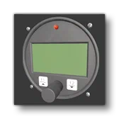
Coming Soon.
Asobo_MPA_GNS430
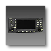
This is a GPS radio with NAV / COM that can be used in any aircraft. For an example, it is currently used by the Skyship 600 and other aircraft in the simulation.
Expected behavior parameters and their default values:
<COM_INDEX>1</COM_INDEX>
<NAV_INDEX>1</NAV_INDEX>
<CIRCUIT_ID>1</CIRCUIT_ID>
<AVIONICS_CIRCUIT_ID>'avionics'_n</AVIONICS_CIRCUIT_ID>
<POTENTIOMETER>1</POTENTIOMETER>
<SCREEN_EMISSIVE_CODE>(L:AS430_ManualBrightness_Value, Percent over 100) (A:AMBIENT LIGHT SENSOR, Number) 0 4000 0.001 1 (F:MapRange) (L:AS430_ManualBrightness_Enabled, Bool) ?</SCREEN_EMISSIVE_CODE>COM_INDEX: Contains the index of the COM channel (between 1 and 3).NAV_INDEX: Contains the index of the NAV channel (between 1 and 3).CIRCUIT_ID: Contains the index of the circuit to use to verify that the panel is powered. The name of the circuit can be used if using the'Name'_nsyntax.AVIONICS_CIRCUIT_ID: Contains the index of the avionics circuit to use. For reasons related to backwards compatibility, you have to link the state of theCIRCUIT_IDto the avionics + the volume of the COM, which is why this parameter is used.POTENTIOMETER: Contains the index of the potentiometer to use for the brightness of the emissive component of the decals.SCREEN_EMISSIVE_CODE: This can be used to override the default logic of the emissive of the screen. If not set, the default logic will automatically tune the brightness based on the current light conditions.
The supported VCockpit parameters are the standard ones:
VCockpit01_htmlgauge00_file, NavSystems/WTGNSv2/WT430/WT430.htmlVCockpit01_htmlgauge00_params: This is empty by default but will require the following parameter definition in the attached_objects.cfg (see VCockpit Parameters, above, for more information).NavIndex- Sets the NAV channel for the JavaScript side of the panel.ComIndex- Sets the COM channel for the JavaScript side of the panel.
For more information and additional setup details please see the following page on the MSFS Avionics Framework website:
Asobo_MPA_GNS530
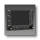
This is a GPS radio with NAV / COM that can be used in any aircraft. For an example, it is currently used by the Cessna 172 Classic in the simulation.
Expected behavior parameters and their default values:
<COM_INDEX>1</COM_INDEX>
<NAV_INDEX>1</NAV_INDEX>
<CIRCUIT_ID>1</CIRCUIT_ID>
<POTENTIOMETER>1</POTENTIOMETER>
<SCREEN_EMISSIVE_CODE>(L:AS530_ManualBrightness_Value, Percent over 100) (A:AMBIENT LIGHT SENSOR, Number) 1 4000 0.001 1 (F:MapRange) (L:AS530_ManualBrightness_Enabled, Bool) ?</SCREEN_EMISSIVE_CODE>COM_INDEX: Contains the index of the COM channel (between 1 and 3).NAV_INDEX: Contains the index of the NAV channel (between 1 and 3).CIRCUIT_ID: Contains the index of the circuit to use to verify that the panel is powered. The name of the circuit can be used if using the'Name'_nsyntax.POTENTIOMETER: Contains the index of the potentiometer to use for the brightness of the emissive component of the decals.SCREEN_EMISSIVE_CODE: This can be used to override the default logic of the emissive of the screen. If not set, the default logic will automatically tune the brightness based on the current light conditions.
The supported VCockpit parameters are the standard ones:
VCockpit01_htmlgauge00_file, NavSystems/WTGNSv2/WT530/WT530.htmlVCockpit01_htmlgauge00_params: This is empty by default but will require the following parameter definition in the attached_objects.cfg (see VCockpit Parameters, above, for more information).NavIndex- Sets the NAV channel for the JavaScript side of the panel.ComIndex- Sets the COM channel for the JavaScript side of the panel.
For more information and additional setup details please see the following page on the MSFS Avionics Framework website:
Asobo_MPA_GTN650
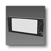
This is a transponder that can be used in any aircraft. For an example, it is currently used by the Cabri and other aircraft in the simulation.
Expected behavior parameters and their default values:
<CIRCUIT_ID>1</CIRCUIT_ID>
<COM_ID>1</COM_ID>CIRCUIT_ID: Contains the index of the circuit to use to verify that the panel is powered. The name of the circuit can be used if using the'Name'_nsyntax.COM_ID: Contains the index of the COM channel (between 1 and 3).
The supported VCockpit parameters are the standard ones:
VCockpit01_htmlgauge00_file, NavSystems/WTGNSv2/WT530/WT530.htmlVCockpit01_htmlgauge00_params
Asobo_MPA_Longitude
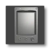
Coming Soon.
Asobo_Radar_Altimeter_AS416
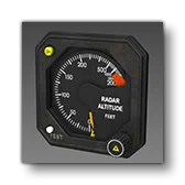
This is a generic analogue radar altimeter gauge. For an example, it is currently used by the H125 in the simulation. This SimAttachment is “plug and play” and does not require any additional setup.
Asobo_Radio_Com_AS92
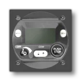
Coming Soon.
Asobo_Radio_Com_AS196
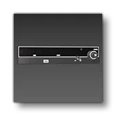
This is a simple radio that can be used in any aircraft. For an example, it is currently used by the Skyship 600 in the simulation.
Expected behavior parameters and their default values:
<COM_ID>1</COM_ID>
<CIRCUIT_ID>1</CIRCUIT_ID>COM_ID: Contains the index of the COM channel (between 1 and 3).CIRCUIT_ID: Contains the index of the circuit to use to verify that the panel is powered. The name of the circuit can be used if using the'Name'_nsyntax.
The supported VCockpit parameters are the standard ones:
VCockpit01_htmlgauge00_file, Helicopters/AS650/dist/AS650.htmlVCockpit01_htmlgauge00_params: This is empty by default.
Asobo_Radio_Com_AS760
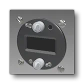
Coming Soon.
Asobo_Radio_Com_AS6201
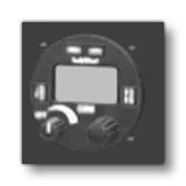
Coming Soon.
Asobo_Radio_Com_G225
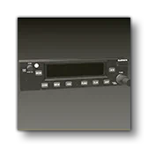
This is a Garmin G225 radio that can be used in any aircraft. For an example, it is currently used by the AT802 in the simulation.
Expected behavior parameters and their default values:
<COM_ID>1</COM_ID>
<CIRCUIT_ID>1</CIRCUIT_ID>COM_ID: Contains the index of the com channel (between 1 and 3).CIRCUIT_ID: Contains the index of the circuit to use to verify that the panel is powered. The name of the circuit can be used if using the'Name'_nsyntax.
The supported VCockpit parameters are the standard ones:
VCockpit01_htmlgauge00_file, Generic/Radios/AS225/AS225.htmlVCockpit01_htmlgauge00_params: This is empty by default.
Asobo_Radio_Com_Nav_G225
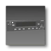
Coming Soon.
Asobo_Radio_Com_SL30
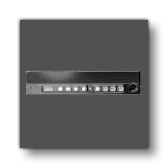
Coming Soon.
Asobo_Slip_Indicator_01

This is a generic analogue slip indicator. For an example, it is currently used by the E330 in the simulation. This SimAttachment is “plug and play” and does not require any additional setup.
Asobo_Slip_Indicator_02
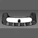
Coming Soon.
Asobo_Slip_Indicator_03

Coming Soon.
Asobo_Spotlight_C4A
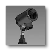
Coming Soon.
Asobo_Tablet_Generic_8_3

This is a generic small EFB tablet. This SimAttachment is “plug and play” and does not require any additional setup. Simply add it to the interior of your aircraft and you should have a fully functional basic EFB.
Asobo_Tablet_Generic_10_9

This is a generic large EFB tablet. This SimAttachment is “plug and play” and does not require any additional setup. Simply add it to the interior of your aircraft and you should have a fully functional basic EFB.
Asobo_Tachometer_01
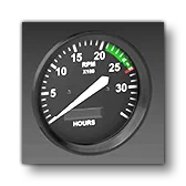
This is a generic tachometer. For an example, it is currently used by the C172 Classic in the simulation. This SimAttachment is “plug and play” and does not require any additional setup.
Asobo_Transponder_AS21
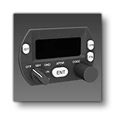
This is a small transponder that can be used in any aircraft. For an example, it is currently used by the Cabri in the simulation.
Expected behavior parameter and its default value:
<CIRCUIT_ID>1</CIRCUIT_ID>CIRCUIT_ID: Contains the index of the circuit to use to verify that the panel is powered. The name of the circuit can be used if using the'Name'_nsyntax.
The supported VCockpit parameters are the standard ones:
VCockpit01_htmlgauge00_file, Generic/Transponders/AS21/AS21.htmlVCockpit01_htmlgauge00_params: This is empty by default.
Asobo_Transponder_AS76A
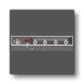
Coming Soon.
Asobo_Transponder_AS76C
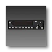
This is a simple transponder that can be used in any aircraft. For an example, it is currently used by the Skyship 600 in the simulation.
Expected behavior parameters and their default values:
<CIRCUIT_ID>1</CIRCUIT_ID>
<POTENTIOMETER>1</POTENTIOMETER>
<DECAL_POTENTIOMETER>7</DECAL_POTENTIOMETER>CIRCUIT_ID: Contains the index of the circuit to use to verify that the panel is powered. The name of the circuit can be used if using the'Name'_nsyntax.POTENTIOMETER: Contains the index of the potentiometer to use for the brightness of the screen.DECAL_POTENTIOMETER: Contains the index of the potentiometer to use for the brightness of the emissive component of the decals.
The supported VCockpit parameters are the standard ones:
VCockpit01_htmlgauge00_file, Generic/Transponders/KT76C/KT76C.htmlVCockpit01_htmlgauge00_params: This is empty by default.
Asobo_Transponder_G330
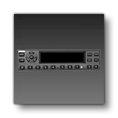
This is a simple transponder that can be used in any aircraft. For an example, it is currently used by the AT 802 in the simulation.
Expected behavior parameters and their default values:
<CIRCUIT_ID>1</CIRCUIT_ID>
<DECAL_POTENTIOMETER>7</DECAL_POTENTIOMETER>CIRCUIT_ID: Contains the index of the circuit to use to verify that the panel is powered. The name of the circuit can be used if using the'Name'_nsyntax.DECAL_POTENTIOMETER: Contains the index of the potentiometer to use for the brightness of the emissive component of the decals.
The supported VCockpit parameters are the standard ones:
VCockpit01_htmlgauge00_file, Generic/Transponders/AS330/AS330.htmlVCockpit01_htmlgauge00_params: This is empty by default.
Asobo_Turn_Coordinator_01

This is a generic analogue turn coordinator. For an example, it is currently used by the C172 Classic or the Skyship in the simulation. This SimAttachment is “plug and play” and does not require any additional setup.
Asobo_Turn_Coordinator_02
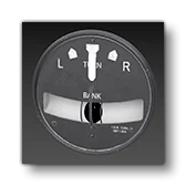
This is a generic analogue turn coordinator. This gauge is not currently used by any default aircraft int he simulation. This SimAttachment is “plug and play” and does not require any additional setup.
Asobo_VoltAmps_Indicator
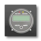
Coming Soon.
Asobo_VSI_01
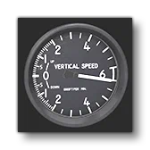
This is a generic analogue vertical speed indicator. For an example, it is currently used by the E330 in the simulation. This SimAttachment is “plug and play” and does not require any additional setup.
Asobo_VSI_02
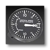
This is a generic analogue vertical speed indicator. This is currently not used by any of the default aircraft in the simulation. This SimAttachment is “plug and play” and does not require any additional setup.
Asobo_VSI_03
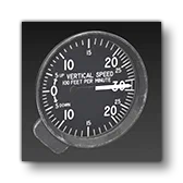
This is a generic analogue vertical speed indicator. This is currently not used by any of the default aircraft in the simulation. This SimAttachment is “plug and play” and does not require any additional setup.
Asobo_VSI_9
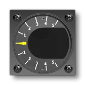
Coming Soon.
Asobo_VSI_10
Coming Soon.
Asobo_VSI_AS8
Coming Soon.
WorkingTitle_IFD540
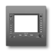
This is an Avidyne IFD540 GPS navigator unit, which can be used in any aircraft.
Expected behavior parameters and their default values:
<INSTRUMENT_ID>1</INSTRUMENT_ID>
<CIRCUIT_ID>1</CIRCUIT_ID>INSTRUMENT_ID: Contains the index of this unit, and should be unique among all IFD instruments in the aircraft. It must also match theVCockpit01_htmlgauge00_paramsparameters (see below).CIRCUIT_ID: Contains the index of the circuit to use to verify that the panel is powered. The name of the circuit can be used if using the'Name'_nsyntax.
The supported VCockpit parameters are the standard ones:
VCockpit01_htmlgauge00_file,NavSystems/WTIFD/IFD.htmlVCockpit01_htmlgauge00_params: This is empty by default but will require the following parameter definition in the attached_objects.cfg.Index- Contains the index of this unit, and should be unique among all IFD instruments in the plane. It must also match theINSTRUMENT_IDbehavior parameter mentioned above.IfdType- Contains the IFD model, and should always be “IFD540”.
For more information and additional setup details please see the following page on the MSFS Avionics Framework website:
WorkingTitle_IFD550
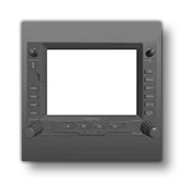
This is an Avidyne IFD550 GPS navigator unit with an artificial horizon and synthetic vision, that can be used in any aircraft.
Expected behavior parameters and their default values:
<INSTRUMENT_ID>1</INSTRUMENT_ID>
<CIRCUIT_ID>1</CIRCUIT_ID>INSTRUMENT_ID: Contains the index of this unit, and should be unique among all IFD instruments in the aircraft. It must also match theVCockpit01_htmlgauge00_paramsparameters (see below).CIRCUIT_ID: Contains the index of the circuit to use to verify that the panel is powered. The name of the circuit can be used if using the'Name'_nsyntax.
The supported VCockpit parameters are the standard ones:
VCockpit01_htmlgauge00_file,NavSystems/WTIFD/IFD.htmlVCockpit01_htmlgauge00_params: This is empty by default but will require the following parameter definition in the attached_objects.cfg (see VCockpit Parameters, above, for more information).Index- Sets the NAV channel for the JavaScript side of the panel.IfdType- Contains the IFD model, and should always be “IFD550”.
For more information and additional setup details please see the following page on the MSFS Avionics Framework website: