
PaintedLine Objects
A Painted Line object is an object element that is used to add arbitrary length lines to areas within an airport. When you select this object type the Objects window will show the following basic painted line types:
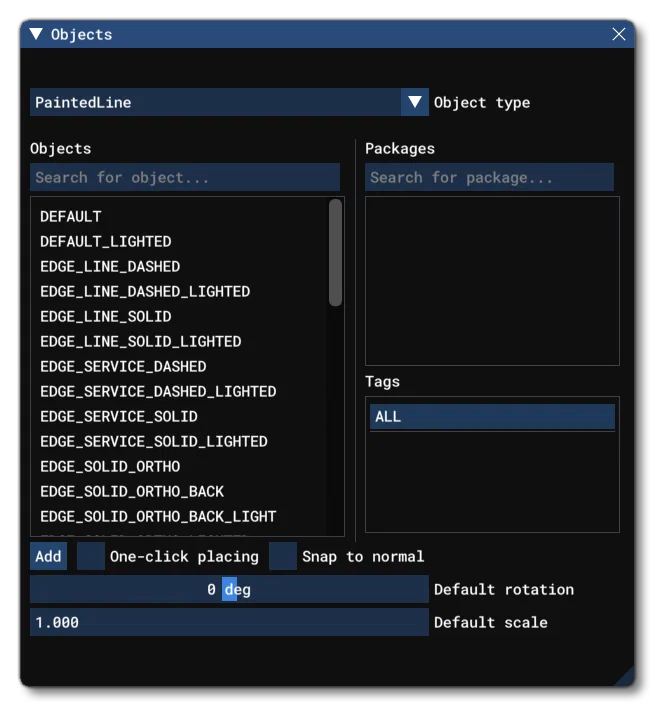
Painted line object elements are a purely visual effect that can be used to better mark out areas and paths in your airport. To add one to your airport, click the button, or select One-Click Placing. Either of those options will add a red dot to the mouse cursor in the world view and you can then use ⌃ Ctrl + left mouse click to place points in the world, creating a “path” for the painted line. When you have added the points you require to create the path, you can then hit the ⏎ Enter key to finalise the painted line path. Note that if you wish to remove the painted line object from the world, you can select it and then press the ␡ key.
Painted Line objects require one or more Airport Objects to be present in the scene, and must be added to an airport group in The Scenery Editor. If no airport is present then they cannot be used. Also note that if they are placed too far away (ie: outside the airport Object Test Radius) then they will not be rendered.
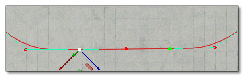
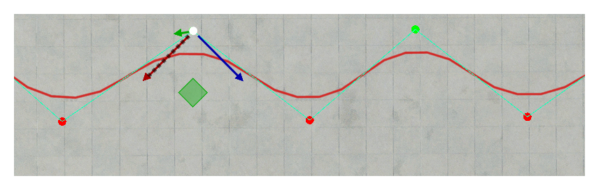
Once placed in the world, the whole line can be moved using the Translate Gizmo or it can be rotated using the Rotate gizmo. It is also possible to click on any specific point along the path and then use the translate gizmo to move that point - the painted line will update accordingly. You can also select various points together by using ⌃ Ctrl + left click on individual points, or by using ⇧ Shift + left click + Drag to select multiple points. Selected points will turn green and these points can then be edited together, as illustrated in the image below (mouse over the image to see the edition):
When editing Painted Line objects, you will have the following additional options for the right mouse button menu (see here for information on the general RMB options - Scene RMB Menu):

Add Point: Using this option will add a new point to the line path at the mouse position which can then be edited as normal.
Remove Point: Selecting one or more points on the line path and choosing this will remove the point(s) from the painted line.
Split Edge: Clicking the RMB on the path of the painted line and selecting this option will add a new point on the path, halfway between the existing points at either end of the selected edge.
Resume Editing: Selecting this option will enable you to continue defining the painted line path shape, using ⌃ Ctrl + click to add new points, and using ⏎ Enter to finalise the edition.
Select All With The Same Type: Choosing this option will select every painted line object element in the current airport that shares the same type value. This permits you to mass-edit certain properties.
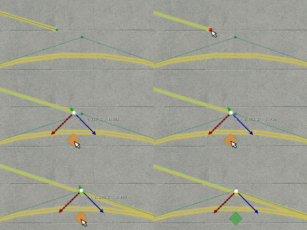
Finally, it’s worth noting that, by default, when you have multiple painted line objects and want them to connect, moving the end of one painted line object near a path point for another, will cause them to automatically join, as shown in the image below (note that this will depend on the type of painted line being used, as well as the True Angle setting):
Properties
The Properties window for a Painted Line object looks like this:
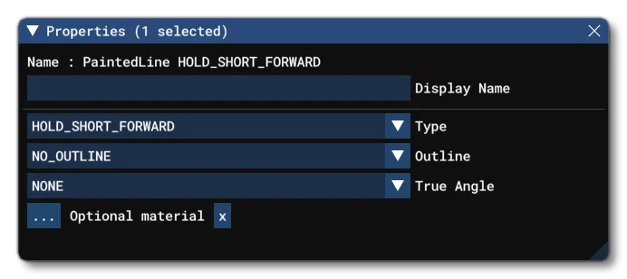
Name
This is the name of the element as defined by its object type properties.
Display Name
This is the name of the element as it will be displayed in the The Scenery Contents List. This can be edited and is helpful for identifying elements when you have a lot of items in the content list.
Type
This is where you can select the type of painted line being created. The options here are the same as those available when you select one of the elements from the Options window:
NOTEThe “LIGHTED” versions of the different Painted Lines are the same as the “normal” versions, only they will have lights added to them.
| Type | Illustration |
|---|---|
| DEFAULT / DEFAULT_LIGHTED | 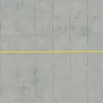 |
| EDGE_LINE_DASHED / EDGE_LINE_DASHED_LIGHTED | 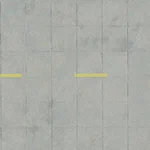 |
| EDGE_LINE_SOLID / EDGE_LINE_SOLID_LIGHTED | 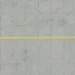 |
| EDGE_SERVICE_DASHED / EDGE_SERVICE_DASHED_LIGHTED | 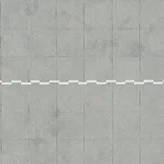 |
| EDGE_SERVICE_SOLID / EDGE_SERVICE_SOLID_LIGHTED |  |
| EDGE_SOLID_ORTHO / EDGE_SOLID_ORTHO_LIGHTED | 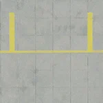 |
| EDGE_SOLID_ORTHO_BACK / EDGE_SOLID_ORTHO_BACK_LIGHTED |  |
| ENHANCED_CENTER / ENHANCED_CENTER_LIGHTED | 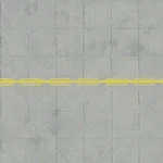 |
| HOLD_SHORT_BACKWARD / HOLD_SHORT_BACKWARD_LIGHTED | 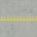 |
| HOLD_SHORT_BACKWARD_MARKED / HOLD_SHORT_BACKWARD_MARKED_LIGHTEDNote that the markings for this type are auto-generated based on the proximity to a runway and a taxiway path. |  |
| HOLD_SHORT_FORWARD / HOLD_SHORT_FORWARD_LIGHTED | 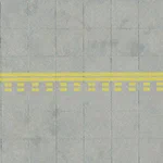 |
| HOLD_SHORT_FORWARD_MARKED / HOLD_SHORT_FORWARD_MARKED_LIGHTEDNote that the markings for this type are auto-generated based on the proximity to a runway and a taxiway path. | 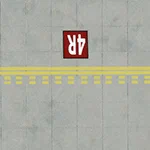 |
| HOLD_SHORT_TAXIWAY / HOLD_SHORT_TAXIWAY_LIGHTED | 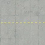 |
| ILS_HOLD_SHORT / ILS_HOLD_SHORT_LIGHTED | 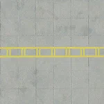 |
| NON_MOVEMENT / NON_MOVEMENT_LIGHTED | 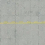 |
| NON_MOVEMENT_BACK / NON_MOVEMENT_BACK_LIGHTED |  |
| SERVICE_DASHED / SERVICE_DASHED_LIGHTED | 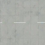 |
| SLIM_RED / SLIM_RED_LIGHTED | 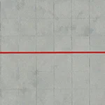 |
| WIDE_RED / WIDE_RED_LIGHTED |  |
| WIDE_WHITE / WIDE_WHITE_LIGHTED |  |
| WIDE_YELLOW / WIDE_YELLOW_LIGHTED |  |
Outline
This option permits you to add a black outline to the chosen line type. Note that not all options will be available for all the different line types.
| Outline | Illustration |
|---|---|
| NO_OUTLINE | |
| LINE |  |
| BORDER | 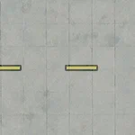 |
| FIT | 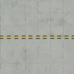 |
True Angle
This setting controls how the painted line will conform to the path that you define for it. By default, the line will be painted using spline curves between points, unless the angle between points is either very close to 90° - in which case it will “snap” to a right angle - or a very acute angle - in which case the line will conform exactly to the path. However you can force the line to conform to the path you created under different circumstance using the options here, which are:
NONE - The line will be painted using spline curves and/or right angles or acute angles.
BEGIN - The line starting at the first point on the path will conform exactly to the path, and not automatically join with other painted lines.
END - The line ending at the last point on the path will conform exactly to the path, and not automatically join with other painted lines.
BOTH_ENDS - The lines starting and ending on the first and last points of the path will conform exactly to the path, and not automatically join with other painted lines.
ALL_POINTS - The painted line will conform exactly to the path along all points of the path.
Some painted lines will always conform to the path true angle, for example HOLD_SHORT_FORWARD / BACKWARD.
Optional Material (Not available for World Hub Airports)
This option allows you to set the material that is used to render the painted line. Clicking the button will open The Material Editor, and you can then drag a material onto the button. The button will change to show the name of the chosen material and it will be applied to the painted line in the world.
IMPORTANT!When being rendered, painted lines are baked into the terrain textures along with the apron/runway that they are on. This helps reduce the polycount and permits the element to be terraformed. However, it also means that the texture quality won’t be any greater than the resolution of the terrain textures themselves. In general, this resolution is around 4mm/pixel at the equator, with the best/highest resolution terrain textures reserved for higher LODs so we have a better quality for airports. For users, they will experience the best resolution possible setting the “Terrain level of detail” option to its maximum value.