Terrain
The Terrain option from the Debug menu will open up the following sub-menu:
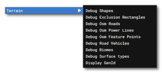
This menu has the following debug options for terrain:
Draw On Terrain
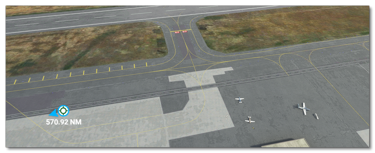
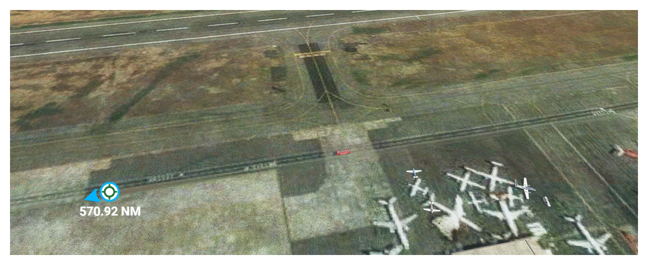
When enabled, surfaces and other items will be drawn on top of the base terrain photogram textures. When disabled, the terrain photogram will be drawn only. Mouse over the image below to see the difference this makes when enabled or disabled. This option is enabled by default.
Draw Shapes
This option is for enabling or disabling the different polygon shapes that may have been used to generate terrain. By default this is enabled.
Debug Shapes
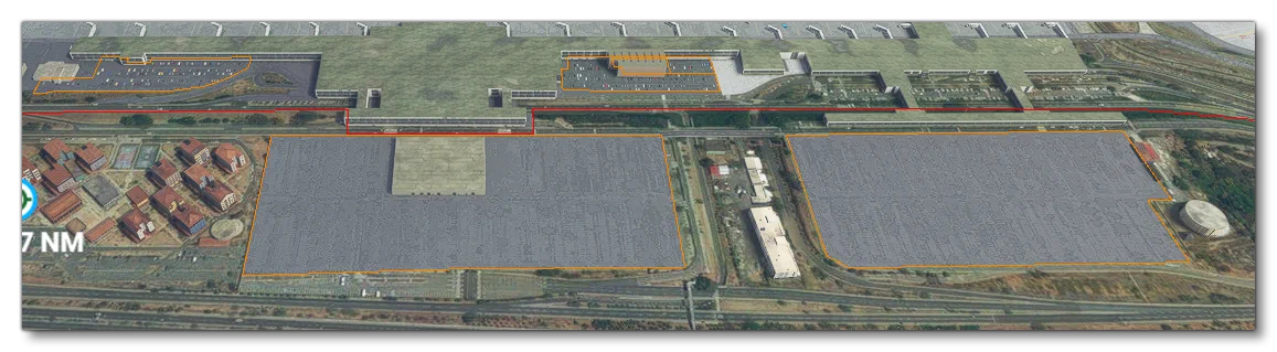
Enabling this option will outline the different polygon shapes used to generate terrain.
This will open an additional window for toggling further information:
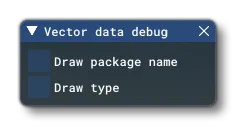
Draw Package Name will draw the name of the add-on package that the polygon (vector) data comes from, while Draw Type will draw information about the type of data the polygon is associated with (eg
NoTIN - Buildings, orNoTIN - Airport, etc…)Debug Exclusion Rectangles
This option permits you to debug any exclusion rectangles that are used in the add-on. It will open the following window that permits you to filter the the visuals to show more or less information:
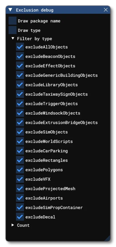
Checking Draw Package Name will add an overlay text to the rectangles with the name of the package they belong to, while checking Draw Type will draw the type of things the rectangle is excludding. You can also filter the rectangles using the Filter By Type list. FInally, at the bottom, you have the Count section, which gives you a numeric breakdown of the packages and how many rectangles are included within them.
Debug OSM Roads
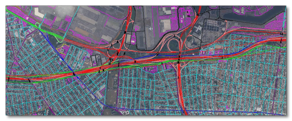
Enabling this option will show all the debug information for the OSM road system in the simulation.
Debug OSM Powerlines
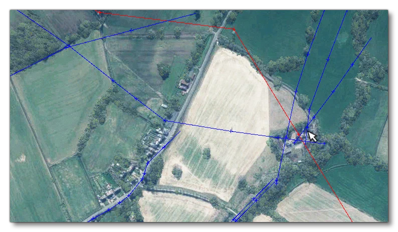
Enabling this option will show all the debug information for the OSM powerline system in the simulation. Red lines are major powerlines with tall masts and the blue lines are minor powerlines with smaller masts.
Debug OSM Feature Points
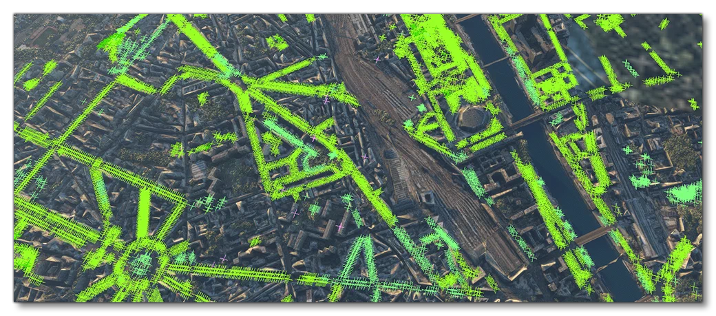
When this option is enabled, various OSM feature points will be marked in the simulation using coloured crosses.
 NOTE
NOTEThis option can cause severe lag in areas where there are a lot of feature points.
Each colour represents the following features:
| Colour | Description |
|---|---|
| Lime Green | Broadleaf trees and shrubs. |
| Green | Needle leaved trees and shrubs. |
| Light Green | Palm trees. |
| Yellow-Green | Leafless trees and shrubs. |
| Pale Green | Mixed leaf trees and shrubs. |
| White | Horizontal turbine. |
| Gray | Vertical turbine. |
| Red | Windmill with vanes. |
| Dark Red | Windmill without vanes. |
| Orange | Oil/petroleum well. |
| Light Blue | Water well. |
| Dark Blue | Water tower. |
| Magenta | Generic/unknown mast of some kind. |
| Pink | COMs mast. |
| Deep Pink | Communication tower. |
Debug Road Vehicles
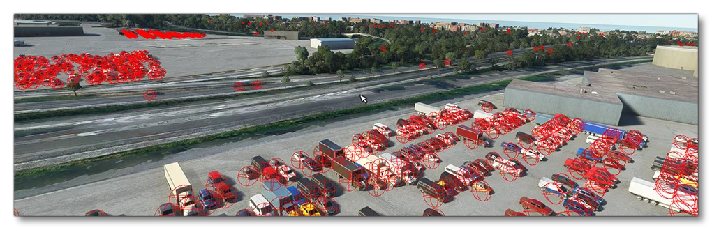
When this option is enabled, all road vehicles will be shown using a red bounding sphere:
Debug Biomes

This window offers multiple debug tools related to the different biomes in the world. It is designed to be used in conjunction with the Biomes Editor. You can find full details on the contents of this window on the following page:
Debug Surface Types
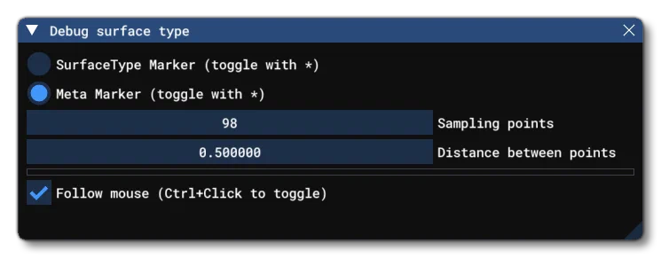
This window allows you to see a visual representation of the different ground surface types. The display will initially be centered around the mouse and show a square area of sample points showing either surface type, or the meta-marker for each point (you can toggle between the two with the key). Meta-markers are the ones added manually through scenery and other means, and are more nuanced and detailed, while the surface types are generated through machine learning and are more general and used primarily for vegetation and other large-scale geographic features. Note that from this window you can also change the number of sample points, and the distance between them, so you can expand/contract the area depending on what you require.
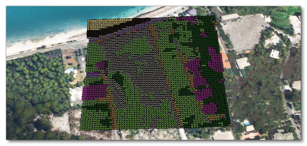
The table below shows the various acronyms and colours that are used, and what surface type / meta marker they represent:
Meta Markers
| Colour Name | Acronym | Description |
|---|---|---|
| Pink | CRT | Concrete. |
| Green | G | Grass, low vegetation, soft, bumpy ground that can be landed on. |
| Pink | WFS | Legacy water from FSX. |
| Pink | GB | Grass, low vegetation, bumpy ground that cannot be landed on. |
| Dark Grey | A | Asphalt. |
| Bright Green | SG | Short grass. |
| Bright Green | LG | Long grass. |
| Pink | HT | Hard turf. |
| Light grey | SN | Snow. |
| Pink | ICE | Ice. |
| Mid Brown | URB | Urban buildings and concrete. |
| Dark Green | FRT | Forest and high vegetation. |
| Light Brown | D | Dirt and mud, in particular for dirt runways. |
| Pink | COR | Coral, used for coral runways. |
| Grey Brown | GRV | Gravel, in particular for gravel runways. |
| Pink | OTR | Used for oil treated (tar-and-chip) runways. |
| Pink | STM | Used for steel mats (steel mesh) temporary runways. |
| Pink | BIT | Bituminous surfaces. |
| Pink | BRI | Brickwork. |
| Pink | MCD | Macadam (compacted small stones). |
| Pink | PLA | Wooden planks. |
| Yellow | SND | Sand. |
| Pink | SHA | Shale. |
| Pink | TMC | Tar macadam. |
| Pink | WFT | Legacy Wright flyer track from FSX. |
| Blue | R | Rivers and creeks. |
| Blue | WW | Waste water. |
| Dark Blue | W | Large bodies of water. |
| Blue | P | Ponds. |
| Blue | L | Lakes. |
| Blue | O | Ocean. |
| Pink | P | Painted surfaces. |
| Dark Grey | R | Roads. |
| Pink | EG | Grass erasure. |
| Mid Grey | RCK | Rocky surfaces. |
| Light Brown | SCR | Scree. |
| Pink | DST | Dusty surfaces. |
| Brown | MUD | Mud. |
| Light Blue | UKN | An unknown (but still valid) surface. |
| Orange | UDF | An unknown (but invalid) |
Surface Types
| Colour Name | Acronym | Description |
|---|---|---|
| Mid brown | DAM | Dirt and mud. |
| Red Brown | RS | Rocks. |
| Light Brown | DAG | Dust and gravel. |
| Black | SAB | Scree and boulders. |
| Yellow | SND | Sand. |
| Green | LV | Low vegetation. |
| Dark Green | HV | High vegetation. |
| Purple | BAC | Building and concrete. |
| Blue | W | Water. |
| Dark Lilac | A | Asphalt. |
| White | SNW | Snow. |
| Lilac | CLD | Clouds. |
| Pink | PLG | Ploughed land. |
| Pink | CLF | Cliffs. |
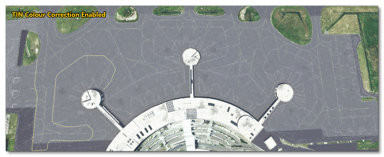
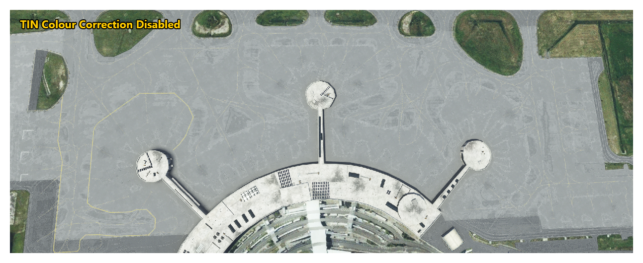
Disable TIN Colour Correction
This option will disable any colour correction that has been applied from TIN data. Mouse over the image below to see what kind of difference this can make:
Display GenId
This window is purely for Microsoft Flight Simulator 2024 debugging and should not be used under any circumstances.