GEOMETRY - TAIL
NOTE: This page is currently WIP.
The Horizontal Tail
To adjust the horizontal tail's vertical and longitudinal position you can change the Pos Lon and Pos Vert (in ft) inputs in the SimObject Editor, or edit the htail_pos_lon and htail_pos_vert parameters in the flight_model.cfg. You'll also want to adjust the horizontal tail Thickness Ratio, which is the htail_thickness_ratio parameter in the CFG file.

The calculation for local thickness is as follows:
$$\textrm{Local thickness} = \textrm{local_chord(x)} \times \textrm{htail_thickness_ratio}, x = \textrm{lateral_coord}$$
Next you'll want to adjust the Area, the Sweep, and the Span of the horizontal tail based off of the data you have or using a visual alignment to the model. These parameters are htail_area, htail_span, and htail_sweep in the CFG file. Note that if the aircraft only has an elevator and no horizontal stabilizer, the horizontal tale area should be set to zero.

You'll want to leave the horizontal tail Incidence (htail_incidence in the flight_model.cfg) at zero for the moment, this value will be used to set the default trim of the aircraft later. However you should set the Elevator Area value in the Controls / Properties section of the Geometry panel, which relates to the elevator_area parameter in the CFG file.

If you don't have these exact values available, you can adjust them visually using the debug overlay such that the surface sensor points cover the area correctly. When finished, you should see the surface sensors aligned to the horizontal tail:

The Vertical Tail
We'll now adjust the Vertical Tail the same as we did for the horizontal, starting with the vertical and longitudinal position using the Pos Vert and Pos Lon inputs, and also the Thickness Ratio. These correspond to the vtail_pos_lon, vtail_pos_vert, and vtail_thickness_ratio in the flight_model.cfg.

The calculation for local thickness is as follows:
$$\textrm{Local thickness} = \textrm{local_chord(x)} \times \textrm{vtail_thickness_ratio}, x = \textrm{lateral_coord}$$
Next you'll want to adjust the Area, the Sweep, and the Span of the vertical tail based off of the data you have or using a visual alignment to the model. These parameters are vtail_area, vtail_span, and vtail_sweep in the CFG file.

Finally you should set the Rudder Area value in the Geometry section, which relates to the rudder_area parameter in the CFG file.

After these steps, you should see the surface sensors aligned to the vertical tail, with a second row aligned about halfway along the tail width:

Rudder
The rudder now needs to be setup, so we'll start by defining the Rudder Area (sqft) and the Rudder Limit in the Geometry section, which are the rudder_area and rudder_limit parameters the flight_model.cfg.

As with the other parameters, if have this exact data then use it. If you don't have the data, you can set a value for the rudder area that is in the same order of magnitude as the aileron and elevator surface areas, and for the rudder limit, this is usually between 15° and 30°. The angle needs to be important enough to achieve the maximum possible crosswind landing and de-crab the aircraft.
Similarly to the ailerons, you also need to define the maximum deflection ratio based on the speed of the aircraft by setting up the table that defines the ratio of rudder control depending on the amount of dynamic air pressure. This is done from the Elasticity Tables section of the SimObject Editor, or by editing the rudder_elasticity_table parameter in the CFG file.

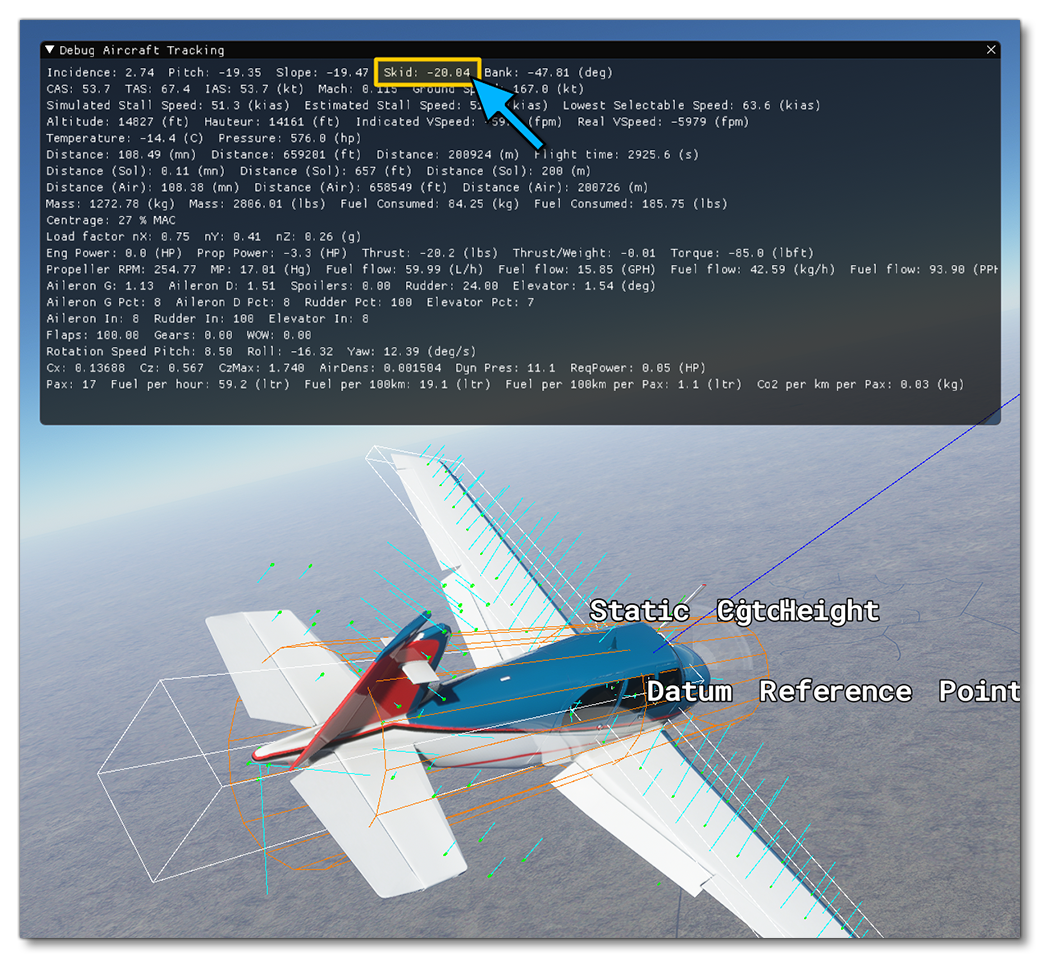
At this stage, you should perform an approach test:
- put the plane at low speed
- go full rudder
- check the skid angle of the airplane
Most planes are able to skid during a stable cross control by about 10° to 20°:
In order to adjust the rudder authority, without changing the rudder surface or maximum deflection angle, which should be based on real data, two parameters are available in the Flight Tuning section of the SimObject Editor, the Rudder Effectiveness and the Rudder Max Angular Scalar. In the flight_model.cfg file these are under the [FLIGHT_TUNING] header, as rudder_effectiveness, and rudder_maxangle_scalar.
 Also, you may want to go back to adjusting your aileron authority at this stage as most aircraft will have enough aileron control to counter a full rudder deflection and maintain a stable cross controlled flight.
Elevator
The elevator is the last thing that we now need to setup, and we'll start by defining the Elevator Area (sqft) and the Elevator Limit, which are the elevator_area, elevator_up_limit, and elevator_down_limit parameters the flight_model.cfg.

As with the other parameters, if have this exact data then use it. If you don't have the data, you can set a value for the elevator area that is in the same order of magnitude as the aileron and rudder surface areas, and for the elevator limit, this is usually between 20° and 30°. The up limit angle needs to be important enough to allow flaring the aircraft upon landing.
Similarly to the ailerons and the rudder, you also need to define the ratio of elevator control depending on the amount of dynamic air pressure. This is done from the Elasticity Tables section of the SimObject Editor, or by editing the elevator_elasticity_table parameter in the CFG file.

Finally, in order to adjust the elevator authority, without changing the elevator surface or maximum deflection angle - which should be based on real data - two parameters are available in the Flight Tuning panel of the SimObject Editor, the Elevator Effectiveness and the Elevator Max Angular Scalar. These are the parameters elevator_effectiveness and elevator_maxangle_scalar parameters in the flight_model.cfg.

At this stage, you should perform a stall test:
- Put the plane at lower speed
- power off
- try to fly steady without descending
You will need to increase your elevator position closer and closer to the upper limit. When the wing stalls, you will see the lift force vectors on the surfaces change color. Yellow is getting close to stall, red is stalling, blue is a fully stalled surface:
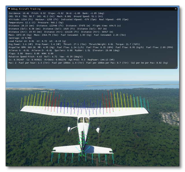
Stalling is computed individually for each surface in the new aerodynamics model of Microsoft Flight Simulator 2024. Most aircraft will allow getting very close to the stall speed limit when the elevator is maintained at the maximum upwards deflection. Some planes will never drop and start descending and others will have a sharp drop. Increasing or decreasing the maximum deflection angle of the elevator, or increasing or decreasing the effect of the elevator deflection, can allow you to achieve a higher or lower maximum angle of attack and therefore change the type of stall of the aircraft.