
FlightSim Materials
The materials listed here are the ones that should be used in all glTF files created as part of add-on assets for the simulation. It may be possible to use your own custom materials, but there is no guarantee that the engine will be able to display these properly, and as such we recommend that you only use the ones listed on this page. Also note that - for 3DS Max - there are extra tools that can be used to make working with FlightSim Materials easier, and these are explained on the following page:
If you are not using 3Ds Max or Blender as your modelling tool, the SDK also comes with a set of glTF Schema files, which can be used to create your own import/export plugins for your tool of use. For more information please see here:
Note On Referencing Materials
It should be noted that - in some files - materials can be referenced by name, for example in the panel.cfg files. In legacy FSX aircraft, these material names were prefixed using the “$” symbol. However, in Microsoft Flight Simulator 2024 this prefix should not be used as it is an internal flag that forces the material to act like a collision material, regardless of whether the collision material option has been checked or not. As such, using this prefix can create unforeseen issues for your aircraft that may be difficult to understand or debug, and should be avoided.
Note For 3DsMax Multi-Materials
In 3DsMax it is possible to create a multi-material, and it’s common to do this when using the different FlightSim Materials, to group all of them together. However the following should be noted:
IDs in the multi-material must be consecutive with no missing ID numbers allowed. Missing ID’s will cause major issues during exporting.
Every sub material must have a material assigned. If the sub-material is empty it will cause export issues.
Avoid having one multi-material plugged into another multi-material, as - again - this will cause an error during the export.
Multi-materials cannot contain animated materials.
Using the FlightSim Materials
The Microsoft Flight Simulator 2024 materials will be available after installing the plugin appropriate for your workflow: either 3DsMax or Blender. In 3DsMax you can find the materials in the material browser under Materials/Standard, and in Blender you can access the material properties from the Object Ribbon on the right, under the Material Properties button.
The images used below are from 3DS Max, for Blender please see here: The Blender Plugin
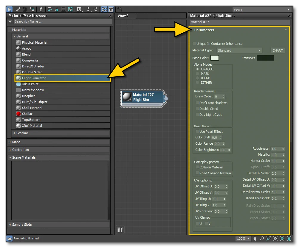
Depending on the Material Type there may be additional parameters available to you as well, and there will also be texture options listed at the bottom, for example:
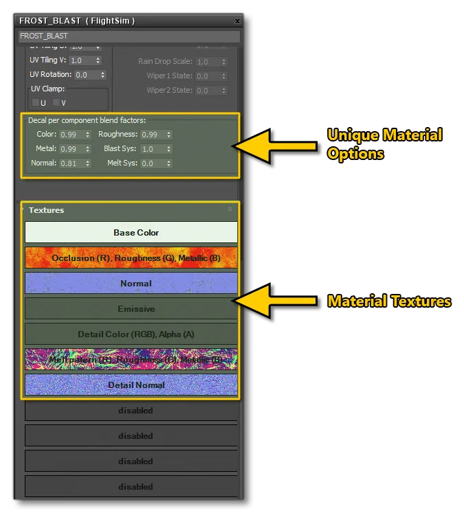
You can find information on the unique material parameters here:
You can find information on the unique textures required by each material here:
It is also possible to create animated materials for use in your packages, with some limitations. You can find more information here:
Microsoft Flight Simulator 2024 Materials
Microsoft Flight Simulator 2024 materials can be one of several material types. These include things like geometry decals and ice. They each have varying support for different blend modes and component textures. If parameters are not supported for the current type, they will be grayed out in the material plugin.
Microsoft Flight Simulator 2024 uses PBR materials, and you can debug these using the Channel Display window in the simulation.
All materials have the same General Parameters but may also require additional parameters, which are listed separately here:
For 3DS Max Users: Make sure that your renderer is set up correctly otherwise some materials will not show correctly. See the 3DS Max Renderer section for details.
Material Types
The available FlightSim Material types are as follows:
Standard
The default material type. Meshes with this type will be rendered in the deferred rendering pass (Alpha Mode = OPAQUE) or in the transparent pass (Alpha Mode = MASK or BLEND).
Additional Parameters: Pearl Parameters (Standard)
Textures: Standard, Decal, PortHole, Glass, FakeTerrain, Ghost, Sail, Propeller, Windflex
Decal
The Decal material type is for geometry decals, which are shapes rendered on top of another mesh. If several decals are to be rendered on top of each other, they have to be in the same sub-mesh, or it will cause rendering artifacts. The order of the sub-materials will determine the order in which they are rendered (first sub-material is rendered first). Meshes with this type will be rendered in a special pass between the deferred and the transparent pass.
Additional Parameters: Decal Per Component Blend Factors (Decal)
Textures: Standard, Decal, PortHole, Glass, FakeTerrain, Ghost, Sail, Propeller, Windflex
Further Information: Airframe Details
IMPORTANT!Currently Decal materials will only be rendered over the following material types: Standard, ClearCoat, Anisotropic, FakeTerrain and SSS.
Windshield
The Windshield material type is used to identify the windshields of the aircraft. It is used mainly for rain effects, otherwise similar to the Glass material type. Meshes with this type will be rendered after the transparent pass. You can find more information here: Windshield Materials.
Additional Parameters: Windshield Parameters, Windshield / Clearcoat Parameters (Rain), Windshield Parameters (Iridescent), Windshield Parameters (Wipers), Windshield Parameters (Debug Shader Windshield)
Textures: Windshield
Further Information: Windshield And Windows
Porthole
This material type will be used for fake views through portholes using parallax scrolling. You can find a complete description of how this can be set up from the following page: Parallax Windows.
Additional Parameters: N/A
Textures: Standard, Decal, PortHole, Glass, FakeTerrain, Ghost, Sail, Propeller, Windflex
Further Information: Parallax Windows
Glass
This material type will be used for generic glass surfaces. Glass and windshield materials are rendered on the same layer, and any number of glass materials can overlap on screen without masking each other. Note that it’s more convenient to have each glass part as separate objects for the draw order sorting to work correctly (for more information see Draw Order).
Additional Parameters: Glass Parameters (glass)
Textures: Standard, Decal, PortHole, Glass, FakeTerrain, Ghost, Sail, Propeller, Windflex
Further Information: Translucent Elements,
GeoDecalFrosted
The GeoDecalFrosted material type is for geometry decals used to add the frost effect, which are shapes rendered on top of another mesh. If several decals are to be rendered on top of each other, they have to be in the same sub-mesh, or it will cause rendering artifacts. The order of the sub-materials will determine the order in which they are rendered (first sub-material is rendered first). Meshes with this type will be rendered in a special pass between the deferred and the transparent pass.
Additional Parameters: Decal Per Component Blend Factors (GeoDecalFrosted)
Textures: GeoDecalFrosted
Further Information: Ice
ClearCoat
This material type will be used to simulate the clearcoat paint that is used as a type of varnish, creating a lacquered effect over coloured paint and decals that have been applied to an aircraft. This material is normally used for the aircraft fuselage, and the main textures are those which you would use in a material to define the look of the fuselage, with a few additional textures/parameters to define how the clearcoat finish will be applied over the supplied base textures/colours.
Additional Parameters: ClearCoat Parameters [ClearCoat], Windshield / Clearcoat Parameters (Rain)
Textures: ClearCoat
Further Information: Clearcoat
ParallaxWindow
This material type will be used to fake building interiors through parallax effects and a special texture mapping.
Additional Parameters: Parallax Parameters (ParallaxWindow)
Textures: ParallaxWindow
Further Information: Parallax Windows
Anisotropic
This material aims to model the light behavior seen in striped micro-surfaces. Such cases may be brushed metal or many types of fabrics. The specular on the material is offset by the two roughness maps following a custom direction in tangent space.
Additional Parameters: N/A
Textures: Anisotropic
Hair
This material type will be used to simulate characters hair.
Additional Parameters: N/A
Textures: Hair
Sub-Surface Scattering / SSS
This material type will be used to simulate skin.
Invisible
This material will be used for non visible objects.
Additional Parameters: N/A
Textures: N/A
Further Information: Airframe Collision Meshes
FakeTerrain
The terrain material type. Meshes with this type will have the same shading system as the terrain in Microsoft Flight Simulator 2024.
Additional Parameters: N/A
Textures: Standard, Decal, PortHole, Glass, FakeTerrain, Ghost, Sail, Propeller, Windflex
FresnelFade
This material will be used to make an object visible based on the camera angle.
Additional Parameters: Fresnel Parameters (FresnelFade)
Textures: FresnelFade
EnvironmentOccluder
This material will be used to hide environmental meshes that eventually penetrate with a mesh with this material assigned.
Additional Parameters: N/A
Textures: N/A
Ghost
This material is designed specifically for use with UI elements in VR (for example “hands”), but could be applied to SimObjects or Scenery elements if required.
Additional Parameters: Ghost Parameters (Ghost)
Textures: Standard, Decal, PortHole, Glass, FakeTerrain, Ghost, Sail, Propeller, Windflex
GeoDecal BlendMasked / GeoDecal Blended Mask
This material is very similar to the Decal material - it is designed for adding additional dynamic details over another mesh - with the addition of parameters to change the sharpness of the blend between materials.
Additional Parameters: Decal Per Component Blend Factors (GeoDecal Blended Mask)
Textures: GeoDecal Blended Mask
Sail
This material is designed for use when making the envelope of a hot air balloon or the wing of a para-glider. Note that when using this material, you will normally want to enable the Double Sided render parameter.
Additional Parameters: Sail Parameters [Sail]
Textures: Standard, Decal, PortHole, Glass, FakeTerrain, Ghost, Sail, Propeller, Windflex
Propeller
This material is only to be used for those elements that rotate as propellers, turbine fans, or rotor-craft blades (helicopters, drones, etc…). Before using this material, the aircraft model requires some very specific setting up, which is explained here: Propellers, Turbines And Blades.
Additional Parameters: N/A
Textures: Standard, Decal, PortHole, Glass, FakeTerrain, Ghost, Sail, Propeller, Windflex
Windflex
This material is not currently used in Microsoft Flight Simulator 2024.
Additional Parameters: WindFlex Parameters [Windflex]
Textures: Standard, Decal, PortHole, Glass, FakeTerrain, Ghost, Sail, Propeller, Windflex
Tree
This material is not currently used in Microsoft Flight Simulator 2024.
Additional Parameters: N/A
Textures: Tree, Vegetation
Vegetation
This material is not currently used in Microsoft Flight Simulator 2024.
Additional Parameters: Vegetation Parameters [Vegetation]
Textures: Tree, Vegetation
The rest of this document explains the different parameters and textures that the various materials can use, starting with the general parameters that are available to almost all the FlightSim materials:


Avoid Duplicate Materials When Using Inheritance (3DS Max Only)
This option is for when you are using Containers in your scene, and these containers are using FlightSim materials. Selecting this option will ensure that there is no conflict between the GUIDs used by the containers and the scene.
When checked, the option will make sure the name of the material remains unique when importing materials from a container, by adding a suffix in the form of [MaterialName]_[ContainerID], where [MaterialName] and [ContainerID] are replaced by the material name and the container ID respectively.
This is currently not supported when using The Blender Plugin.
Albedo / Base Colour


The base color and alpha of the material. These values are linear and can be set by simply clicking on the colour swatch. If a Base Color (Albedo) texture is specified, this value is multiplied with the texel values.
Emissive / Emissive Colour


Note that to help you get the correct emissive multiplier, you can click on the Calc button to open the Emissive Calculator:

This window permits you to calculate the following:
When Lock Luminance is checked - how much total light (the luminous intensity calculated in cd) a surface area of X m² and a luminance of N cd/m².
When Lock Intensity is checked - how many cd/m² a surface area of X m² needs to have to provide N cd of total luminous intensity.
The emissive colour is the colour that will be used for things like lights to create the “glow” effect. If an Emissive Texture is used, this colour is multiplied with the texel values of the texture.
Emissive Scale / Multiplier - This value is used to adjust the luminosity of the emissive colour. For further information on the emissive scale/multiplier, please see the section on Light Materials And Textures.
Day Multiplier - This value is a multiplier that can be used to adapt the brightness of the emissive material during the day time.
Night Multiplier - This value is a multiplier that can be used to adapt the brightness of the emissive material during the night time.
Alpha Mode

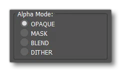
OPAQUE
The material is fully opaque and any alpha values are ignored.
MASK
The material is either fully opaque or fully transparent depending on the alpha value and the specified alpha cutoff value. This mode can be used to simulate geometry such as tree leaves or wire fences. Pixels with an alpha above the alpha cutoff parameter value are discarded, the others are opaque.
BLEND
The output is blended with the background using a traditional blend operation (i.e. the Porter and Duff over operator). This mode can be used to simulate geometry such as gauze cloth or animal fur.
DITHER
The output is blended with the background using a dithering pattern.
Render Parameters


Draw Order
This value modifies the sorting order, and the value can range from from -999 to 999. In the simulation, objects are sorted from back to front using the mesh center. By “mesh center” we mean the actual mesh bounding box center, not the pivot position itself (pivot position does not affect the draw order sort algorithm). As such, the Draw Order parameter can be used to offset the distance used to sort the rendering order, for cases where the meshes center doesn’t provide the correct order. This can be used to avoid rendering artifacts such as flickering when multiple transparent or decal material types are on top of each other in the rendered output. This parameter is effective for Decal, Glass and Windshield materials. In the case of decals, the value strictly specifies the order in which decals are rendered, where a higher value will be drawn above and a lower value will be drawn below. In the case of Glass and Windshield materials, the value is added as an offset to the distance used to sort the objects for rendering.
Don’t Cast Shadows
When checked, objects with this material will not cast shadows.
Double Sided
When checked, back-face culling is disabled and double-sided lighting is enabled. Be aware that the normal of the back-side face is not flipped by default, so you would normally also check the Flip Backface Normal (3DS Max Only) option (3DS Max only). If correct lighting is required without flipping the backface normals the you should use double-sided geometry instead.
Day Night Cycle
When checked, the emissive will be linked to the day/night cycle
Disable Motion Blur
This option is made available for those rare cases when the motion blur applied by the simulation is considered undesirable, for example when the material is already being animated to blur it, for example when the material is for tires or propellers.
Flip Backface Normal (3DS Max Only)
This option will only be available when you have checked the Double Sided option and - when enabled - it will flip the normals of the backface.
Gameplay Parameters


Collision Material
When checked, meshes with this material will have collidable faces. This can be used to create precise colliders, for example for mouse interaction. Use this with low-resolution meshes. You can find more information here: Collision Handling
Road Collision Material
When checked, meshes with this material are considered to be a road. This can be used to define which part of an asset can be used by cars, for example. Use this with low-resolution meshes.
Ground Collision Material
When checked, meshes with this material are considered to be on the ground, but not specifically a road. This can be used to define which part of an asset can be used by flora and fauna, for example. Use this with low-resolution meshes.
UV Options


Offset U/V
Set the UV offset values. Note this option can be animated, for more information see:
Tiling U/V
Set how the UVs will be tiled. Note this option can be animated, for more information see:
Rotation / UV Rotation
Set an angle to rotate the UVs by. Note this option can be animated, for more information see:
Clamp U/V
Clamps UVs on the U and/or V axis.
General Parameters


Metallic Factor / Metallic
The metalness of the material. A value of 1.0 means the material is a metal. A value of 0.0 means the material is a dielectric. Values in between are for blending between metals and dielectrics such as dirty metallic surfaces. This value is linear. If an “Occlusion (R) Roughness(G) Metallic(B)” texture is specified, this value is multiplied with the metallic texel values. Note this option can be animated, for more information see:
Roughness Factor / Roughness
The roughness of the material. A value of 1.0 means the material is completely rough. A value of 0.0 means the material is completely smooth. This value is linear. If an “Occlusion (R) Roughness(G) Metallic(B)” texture is specified, this value is multiplied with the roughness texel values. Note this option can be animated, for more information see:
Occlusion Strength / AO Strength
This option gives you the ability to tweak the occlusion map without breaking the AO map. With this option, you can modify the occlusion strength applied to each pixel of the texture. A value of 0.0 means no occlusion. A value of 1.0 means full texture occlusion, a value of 2.0 means complete dark occlusion, if no texture is specified the default AO texture will be white.
Normal Scale / Normal Strength
The scalar multiplier applied to each normal vector of the texture. This value is ignored if the “Normal” texture is not specified.
Alpha Cutoff
When Alpha Mode is set to
MASK, the Alpha Cutoff property specifies the cutoff threshold. If the alpha value is greater than or equal to the Alpha Cutoff value then it is rendered as fully opaque, otherwise, it is rendered as fully transparent. The Alpha Cutoff value is ignored for other modes.Detail UV Scale / Detail UV Tiling
UV tiling factor for the detail map.
Detail Normal Scale / Detail Normal Strength
The strength factor for the detail normal map.
Blend Mask Threshold / Detail Threshold
Defines the sharpness of the detail blending. T he lower the value, the sharper the blending.
Wear Overlay UV Scale
Not currently used in the simulation.
Wear Blend Sharpness
Not currently used in the simulation.
Wear Amount
Not currently used in the simulation.