
Other Surface Geometry
This page is currently WIP.
Flaps and spoilers
To define flaps and spoilers, there is both an aerodynamic and a geometric definition. The aerodynamic definition we’ve already setup in the previous page, so we need to do the geometric definition, which will be fed into the lift and drag polar curves and will be used to perform the virtual wind tunnel normalization of the aircraft’s surfaces.
After setting the spoiler and flaps geometry, you should see increased lift forces being applied to the wing over the parts of the wing where the flaps are located:

Flaps
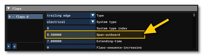
The flaps really only one essential geometric setting which is the ratio of wing span corresponding to how much the flaps will take up on the wing. This is done by changing the Span Outboard (%s) value in the SimObject Editor from the Flaps parameter, or by editing the span-outboard value in the flight_model.cfg:
Spoilers
If the aircraft does not have spoilers, you can leave all parameters in this section set to 0.
The spoiler geometry is defined in the Geometry panel of the SimObject Editor, under the Controls / Properties section. In the flight_model.cfg file, you need to set the following parameters:
spoiler_limit, air_spoiler_limit, spoilerons_available, aileron_to_spoileron_gain, min_ailerons_for_spoilerons, min_flaps_for_spoilerons, spoiler_extension_time, spoiler_handle_available, auto_spoiler_available.

Ailerons
Time now to work on the aileron control as it will improve the general stability of the aircraft. Start by defining the Aileron Area (sqft), which aileron_area in the flight_model.cfg file. If you have this exact data, use it. If you don’t have this data, then you can approximate it and try to maintain the same order of magnitude when defining the rudder and elevator surface areas later.
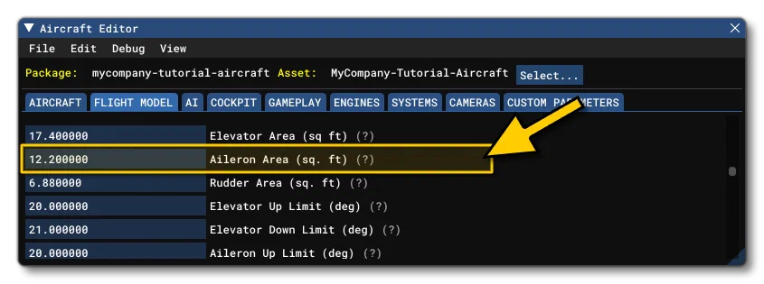
Next you’d set the set the Aileron Up and Aileron Down limit angles (in degrees), corresponding to the in the aileron_up_limit and aileron_down_limit in the CFG file. Again, if you have this exact data, use it, but if you don’t then you can usually get away with setting the up limit to 20 and the down limit to 15.
This type of data is rarely found in a POH but can be found on the website of the FAA(opens in a new tab).

Now you need to define what percentage of length of the wing is covered by the ailerons. Usually, this distance plus the percentage of the length of the wing covered by flaps, is equal to approximately 100% of the total wing length. This can’t currently be set in the editor so you need to edit the aileron_span_outboard parameter in the flight_model.cfg file directly.
Next you can define how much control you want to be applied to the ailerons, depending on the speed of the aircraft. This is a table that defines the ratio of aileron control depending on the amount of dynamic air pressure, and can be set by scrolling to the bottom of the Geometry panel in the SimObject Editor to the section on Elasticity Tables and selecting the Aileron tab. If you are editing the flight_model.cfg file, you’d use the aileron_elasticity_table parameter.

The current dynamic air pressure is displayed on the debug Speed window to help adjust the aileron control depending on the current speed:

At lower speeds, up to climb speed, this ratio is usually 100% and it starts decreasing at cruise speed and can reach values close to zero when the plane is flying over speed, above the red bar (complete loss of authority).
Another adjustment that needs to be made is to define the maximum authority of the ailerons. This will be done to achieve the maximum roll speed that is possible with the aircraft at a given speed, and is set from the Aileron Effectiveness setting in the Flight Tuning section, or using the aileron_effectiveness parameter in the flight_model.cfg file.

If you have this value, then you should use it. Otherwise, most aircraft can achieve maximum roll speeds of more than 30 degrees per second. For a GA aircraft 30 to 60 degrees per second is a good start. The above parameter allows you to scale the aileron authority up or down depending on your needs.
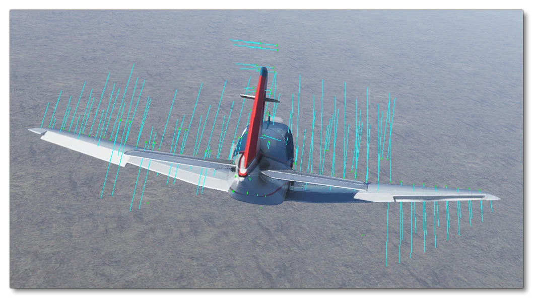
When testing, you can find the current roll speed in the SimObject Editor Tracking debug window, and in the image below you can see an example of the forces that are being applied as a result of the aileron angles when the aileron angles are maximal:
Stability
Finally, it is time to set the aircraft Stability. Based on the dimensions and geometric definition of the aircraft, the surface based aerodynamics simulation automatically calculates the minimum rotational air friction, but because a real airplane is not made of perfect surfaces with a perfect shape, real rotational friction is always going to be higher. So, to adjust the rotational friction you can go to the Flight Tuning panel and edit the Pitch, Roll, and Yaw Stability settings, or edit the flight_model.cfg file pitch_stability, roll_stability, and yaw_stability parameters.

Note that here you need to enter values that are greater than zero to maintain backwards compatibility with the legacy flight model - however, you can enter 0.01, for example, if you want only the minimum rotational friction. If the plane has more roll inertia, you can enter higher values.