
Wing Geometry
There are two ways we can set up the wings, one using the generic wing setup, which is fine for simple aircraft or aircraft with conventional wing configurations, or using the modern geometry wing setup, which permits non-standard wing configurations. For example, with the modern geometry you can easily create a biplane like the Acro Sport II(opens in a new tab), or even something more experimental like the DARPA “SMUT” Model 33(opens in a new tab).
For both wing setups, certain CFG parameters are used in both cases, and we’ll cover these shared parameters first in the sections below. Note that you can adjust the required parameters and then save in the SimObject editor, and the position of the different surface markers will change to reflect the new values. These markers are actually the sampling positions that are used by the flight model to determine how the aircraft will fly, and the goal (with the wings) is to have the front row of markers align with the leading edge of the wing, and the back row of markers to follow approximately the center of the wing. It’s unlikely that these align right now, so we need to continue and define the parameters correctly.
You can enable Live Edition and then select Auto Resync On Changes to see any changes that are made in the editor reflected in the simulation in real-time without the need to save first.
If the aircraft requires more than the standard left and right wing setup, then you should still go ahead and setup the parameters below for the “main” set of wings first. If the aircraft is entirely unconventional, then you should still try to set up these parameters to “best fit” values where possible, and then modify them using the advanced geometry options.
Basic Wing Shape
We’ll start by setting the wing Area and Span in the [AIRPLANE_GEOMETRY] section of the SimObject Editor, which correspond to the parameters wing_area and wing_span in the flight_model.cfg.

Next you can set the Thickness Ratio of the wing in the Geometry panel. This is a ratio of the wing size and most wings are between 2% and 5% thick. In the CFG file, this is the wing_thickness_ratio parameter .
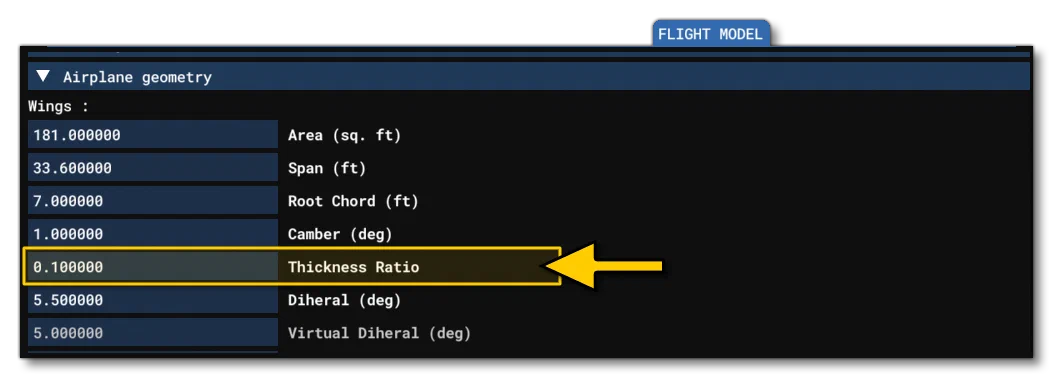
The calculation for this is as follows:
$$\textrm{Local thickness} = \textrm{local\_chord(x)} \times \textrm{wing\_thickness\_ratio}, x = \textrm{lateral\_coord}$$
Wing Positioning And Angles
At this point you need to set the Sweep (wing_sweep) in the Geometry panel and the Aero Center Lift (longitudinal position - aero_center_lift) at the top of the Aerodynamics panel. This second one requires that Compute Aero Center (compute_aero_center) is unchecked (false):


Next, you need to position the wing vertically using Pos Apex Vert (wing_pos_apex_vert) and fine tune the shape using the Root Chord (wing_root_chord), both measured in ft:

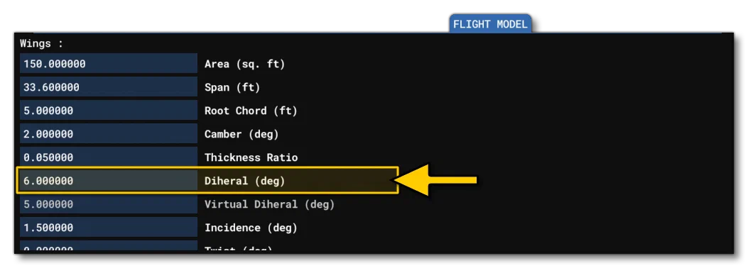
Finally you can set the wing Dihedral (wing_dihedral - in degrees):

At this stage, when seen from the top and the front, you should see that the front line of surface sensors for the wing surfaces are aligned along the leading edge of the wing, and the rear line of surface sensors are aligned along the approximate middle of the wing (this way, the sum of the aerodynamics forces will be aligned at 25% MAC), and the top and bottom surface sensors “sandwich” the wing:

It’s worth noting that even if you don’t have the exact measurements or values required for the above listed parameters, you can still use the visual debugging to get a very close approximation based on the aircraft model. Simply tweak the values until you get the surface sensors in the appropriate position.
Advanced Wings
Generic wings assume that the aircraft has the standard two wing (left/right) configuration, but it may be that your aircraft is non-conventional and has additional wings or canards. These can now be added using the [OBJ_AIRGEO_WING.N] section of the flight_model.cfg. However before getting to that section you first have to decide whether the generic wings are going to be used as well as additional wings, or whether you want all wings to use the advanced geometry options. By default, any additional wings will be added along with the generic ones, but you can disable this by unchecking the enable_aircraft_geometry_wing option:

For this example, we’ll be keeping the generic wing setup, and adding an extra canard “wing” surface to the nose of the DA62, so no changes need to be made to the section above as we’ll be keeping the generic wing definitions. Since this is purely for illustration purposes, all we’ve done is duplicated the wing models of the DA62 using the attached_objects.cfg to position and scale them:

To set up the physics for this canard surface, we need to go to the [OBJ_AIRGEO_WING.N] section and add a new wing geometry object. We’ll give it a name, and also set its approximate position (easily done using the The Edition Gizmo tool), and you’ll notice that it has the same default shape as the “generic” wing:

The initial shape will use all the [AIRPLANE_GEOMETRY] parameters by default, but these can be overridden by setting the appropriate parameters in the wing geometry object (span, area, sweep, etc…). The process here is the same as that for generic wings, ie: change the values to those that you have from the plane data, or - at worse - tweak them such that the surface points are as close as possible to where they should be.