DIRT AND GRIME
An important part of the immersion when flying an aircraft in the simulation is seeing how the activities you participate in affect the aircraft you are flying. This isn't just limited to simulating internal wear and tear however, as it can extend to the airframe and visual assets as well, and it's encouraged to set up your aircraft correctly to reflect this.
In Microsoft Flight Simulator 2024 there five different types of "dirt" that can be applied to an aircraft:
- Simple Dirt
- Insect Splatter
- Runway Dirt (Planes only)
- Leaks / Stains
- Dust
- Mud
NOTE: The order given here is also the order in which the materials should be rendered in the simulation and as such you should be setting the draw-order in the materials to values that follow the above listed order.
The way that the dirt and grime on an aircraft changes over time is achieved in two different ways depending on its kind:
- Progressive Blend: The dirt textures are applied using a simple opacity variation from 0% up to 100% to simulate - for example - the slow accumulation of runway dirt on the underside of the aircraft.
- Progressive Mask: The dirt texture includes a unique grey-scale texture as a mask which is used to progressively expose more and more of the albedo texture and simulate - for example - insect impacts.
Further modification of the dirt/grime density will also be achieved through the use of the mesh Vertex Alpha, where a value of 1 is 100% and a value of 0 is 0%. This will be the primary modifier for applying the dirt to the aircraft.
NOTE: Currently no dirt is applied to propellers or rotors, nor to the wheels, although this may change as the Microsoft Flight Simulator 2024 SDK evolves.
Workflow Overview
When it comes to setting up your aircraft for dirt/grime to be shown in the simulation, each type will require the creation of additional meshes, over multiple LODs. In general, each dirt type will require it's own mesh, which should be created from the LOD2 of the main aircraft geometry mesh. This should be expanded (using the push modifier in 3DS Max, for example), so as not to clip with the main aircraft LOD0 mesh, and also be shown over any additional livery meshes that may exist for the aircraft. The image below is an example "base" dirt / grime / ice mesh that is used by H125 for LODs 0 - 2:

This LOD0 dirt / grime mesh will be used for LOD0, LOD1 and LOD2, and you will need to create a new simplified version of the mesh to be used for LODs 4 and 5, and then create a final - heavily simplified - version for LOD6. Each LOD mesh should be placed in it's own "parent" layer per LOD, and then within each LOD layer, it can be duplicated several times to cover all the dirt layers (if you have set up ice for the aircraft, this can also go in the same parent group).
NOTE: This mesh simplification is crucial as the dirt and grime meshes will be directly added to the overall parts polycount which - if not optimised properly - will make the LODs switch sooner than expected, because of the LOD Selection System. You can find some additional general guidelines here: Excess Vertices In Your Models
Due to the modular nature of aircraft in MSFS 2024, each LOD layer dirt type should then be split into parts to be exported at the end, such that the grime for the wings is exported with the wings, for the fuselage with the fuselage, etc... The image below shows a typical layer setup:

Note that in all the sections given below relating to the different dirt "types", the SDK provides textures that can be simply "plugged in" to the materials that are used in your model editor. In most cases we highly recommend using these textures, especially when it comes to the mud and insect textures, as these are highly specialised textures and very difficult to create. See the Shared Assets section of the documentation for more information.
Simple Dirt
Simple dirt is applied at the same time as the insect splatter effect, but requires it's own mesh and material setup. This kind of dirt is applied mainly to the bottom of the aircraft, wherever there is a close proximity to the ground. For example, the image below shows the simple dirt mesh for a glider, along with the expected "look" in the simulation:

For rotorcraft, the mesh is also applied to the bottom, but it it should additionally cover the entirety of the skids / landing gear:

In these examples you can see that the mesh has been trimmed to cover only the appropriate parts, and then the vertex paint option has been used to change the vertex alpha of the mesh. This is used to create a "fade" along the edges of the mesh and make a more realistic application of the material on the aircraft in the simulation (where white is 100% cover, and black is 0% cover). Note that you should weld any UV seams that may be too visible in the simulation.
When it comes to setting up the material, you should be using the Decal material, along with the Regular_albd.tif texture that is supplied with the SDK:

Insect Splatter
Insect impact splatter is applied at the same time as the simple dirt effect, but requires it's own mesh and material setup.
NOTE: For insect splatter on windshields, please see the Windshield And Windows page.
This kind of grime effect is applied mainly to the leading edges of the aircraft, ie: those that are facing the direction of travel. For example, the image below shows the simple dirt mesh for a glider, along with the expected "look" in the simulation:

For rotorcraft, the mesh is mainly applied to the nose and the leading edges of the skids, since the rotors usually mean that the back edges of the helicopter stay clear of this kind of grime:

In these examples you can see that the mesh has been trimmed to cover only the appropriate parts, and then the vertex paint option has been used to change the vertex alpha of the mesh. This is used to create a "fade" along the edges of the mesh and make a more realistic application of the material on the aircraft in the simulation (where white is 100% cover, and black is 0% cover). Note that you should weld any UV seams that may be too visible in the simulation.
When it comes to setting up the material, you should be using the GeoDecal BlendMasked / GeoDecal Blended Mask material, along with the following textures supplied with the SDK:
- For planes:
- Albedo -
Insects_albd.tif - Geometry Detail Blend Mask -
Insects_Mask.png
- Albedo -
- For rotorcraft:
- Albedo -
Insects_Helico_albd.tif - Geometry Detail Blend Mask -
Insects_Helico_mask.png - Normal -
Insects_Helico_norm.png
- Albedo -

With these albedo textures, the UV setup is very important, as the texture is designed to tile along the U-axis only. The top of the texture is best suited to edges, the bottom-left of the texture is best suited to forward facing fuselage elements that receive heavy impacts, and the bottom-right section is for light impact areas. The following image is an example of correct UV setup (this is the same for both planes and rotorcraft):

Leaks / Stains
Leaks and stains are similar to the simple dirt effect, but requires it's own mesh and material setup. For aircraft, leaks should appear on most openings where some kind of mechanism / oil / lubricant is present. For example, the most common places to see leaks are the landing gear, traps, flaps, ailerons, rudders, and air brakes. Note that most leaks will always point to the back of the aircraft due to airflow when flying, however for enclosed areas like landing gear bays, the leaks can point downwards. In addition, this mesh may also include different stains , for example, those created by the soot from an exhaust.
The image below shows the leak mesh for the DA62 highlighted in blue, along with the expected "look" of the leaks and stains when flying in the simulation:

For rotorcraft, the setup is a bit different because of the hovering nature of such aircraft. So, any leaks can still be set up like plane and point backwards, but these should be carefully positioned so they only appear where they would not be logically influenced by the rotors. You can also create leaks flowing down based on the airflow from the rotors, but try not to mix the two directions as it can look a bit uncanny. Basically, keep everything as logical and realistic as possible, and note that generally you would expect fewer leaks than on a plane. It's also worth noting that there may be additional stains on the fusealge from the soot created by the engine ehaust nozzles:

In these examples you can see that the mesh has been trimmed to cover only the appropriate parts, and any visible seams have been UV welded so they appear correct in the simulation.
When it comes to setting up the material, you should be using the Decal material, along with the Leaks_albd.tif texture that is supplied with the SDK:
NOTE: For soot/exhaust stains, you will have to create your own texture, but the material setup is the same.

With this albedo texture, the UV setup is very important, as the texture is designed to tile along the U-axis only. The top of the texture is best suited for use on objects that have single leak stains (like an oil trap), while the bottom part of the texture is meant for edges with stains, like the flaps. The following image is an example of correct UV setup (this is the same for both planes and rotorcraft):

Runway Dirt
Runway dirt is only applied to planes and like the other effects, it requires it's own mesh and material setup. This kind of dirt is applied mainly to the bottom of the aircraft, wherever dirty water may be thrown or splashed up from having the aircraft rolling down wet runway (and the amount shown in the simulation will depend on the number of hours of ground roll on wet runways). The image below shows the runway dirt mesh (highlighted in blue) for the DA62, along with the expected "look" in the simulation:

When it comes to setting up the material, you should be using the Decal material, along with the Runway_albd.tif texture supplied with the SDK:

The texture supplied with the SDK has been designed for some very specific applications, and as such we suggest the following general UV mapping structure, where:
- This is the line of accumulating runway dirt, and it acts as a border line separating the clean and dirty part of the aircraft.
- This is movement dirt, normally put on the bottom of the aircraft where rain can't reach it and cause streaks.
- This is movement dirt but affected by water, and so has streaks. This is normally put on the sides or curved areas where rain can reach.
- This is splashed dirt, usually placed anywhere dirt from the ground is splashed directly up (like from wheels).

Dust
Dust is applied when the aircraft is landing or rolling through sandy or dry dirt runways, and requires it's own mesh and material setup. For planes this kind of dirt is applied primarily to the underside of the aircraft, but should also accumulate elsewhere, but to a lesser extent. This means that - of all the dirt and grime types - it has the largest mesh and the greatest impact on the total polycount for the aircraft, and as such we do not recommend including this mesh for airliners, as it can have a severe impact on performance. The image below shows the dust mesh for the DA62, along with the expected "look" in the simulation:

For rotorcraft, the dust mesh should be primarily on the bottom of the aircraft, although you can add some extra mesh detail on the top in appropriate areas, but in much less quantity than aircraft:

In these examples you can see that the mesh has been trimmed to cover only the appropriate parts, and then the vertex paint option has been used to change the vertex alpha of the mesh. This is used to create a "fade" along the edges of the mesh and make a more realistic application of the materials on the aircraft in the simulation (where white is 100% cover, and black is 0% cover). Note that you should weld any UV seams that may be too visible in the simulation.
When it comes to setting up the materials, you should be creating two Decal materials (available from the SDK textures) for both planes and rotorcraft:
- The first material uses the following textures, which are all tileable, and should be used for most of the aircraft dust effects:
Dust_albd.tifDust_comp.pngDust_norm.png
- The second material is tileable only along the V-axis, and is designed to be used in areas where strips or splashes of dust are required (eg: tire rims, or around the wheel-bays):
Dust_Spash_albd.tifDust_comp.pngDust_Splash_norm.png
The important thing to note about these textures is that they are greyscale and colour is applied using the albedo value (a good starting value is #7d654e).

Mud
Mud is applied mainly to the bottom of the aircraft, and will be added whenever a rotorcraft is landing on - or a plane is rolling over - wet, unpaved ground surfaces. The amount of dirt added will depend on the type of ground surface and how wet it is, and like the other dirt overlays, its setup requires its own mesh and material. The image below shows the mud mesh for the DA62, along with the expected "look" in the simulation:

For rotorcraft, mud will only really be applied to the skids, but the mesh should also cover the bottom of the aircraft as it is expected that some small splashes will be shown there:

When it comes to setting up the material, you should be using the GeoDecal BlendMasked / GeoDecal Blended Mask material, along with the following textures from the SDK:
Mud_albd.tifMud_mask.pngMud_norm.png

The texture supplied with the SDK has been designed for some very specific applications, and as such we suggest the following general UV mapping structure, where:
- This is the line of accumulating mud on the skids of the helicopter.
- This is the dispersed mud splash, used for the underside of the aircraft where only incidental splashes are located.
- This is the movement mud splash for where a lot of mud has been kicked up by the wheels of the aircraft.
Dirt And Aircraft Variations
When it comes to aircraft with different variations, it may be required to have extra meshes for the different dirt types depending on the aircraft. For example, if you have an aircraft that has a wheeled variant and a variant with floats, you would need to create different meshes for some of the dirt types, since the dispersion will be different. The following image shows the runway dirt meshes on an aircraft with wheels and with floats:

In this example, you can see the that the wheels project runway dirt onto the wings, fuselage, and nose. However, the float variant only has the dirt projected onto the floats themselves, and nowhere else. This means that you will need to create different layer groups for each part, and include the dirt in the same group for those parts so they can be exported together, something like this:

It should be noted that the parts and the dirt layers are exported seperately since having them together can lead to premature LOD switching as - for example - the landing gear would be considered as having more polygons than it actually has due to the dirt mesh. You can still do this if it fits your workflow better, and it can be fine for smaller aircraft, but it's not the recommended process.
File Setup - XML
Each of the different dirt types that you have setup for your aircraft will require it's own Component in the Model Behaviors XML for the part that has the dirt. For example, if you have a fuselage, left and right wings, and engines, then you will need to include the appropriate XML in all those parts for the associated dirt meshes.
The model behavior XML files for each part should always have the following includes (in addition to any other they require):
<CompileBehaviors Version="2">
    <Include ModelBehaviorFile="ASOBO_EX1\\Index.xml"/>
    <Include ModelBehaviorFile="ASOBO_EX1\\DefaultConfig.xml"/>
</CompileBehaviors>
You will then need to include some specific component code to tell the simulation to track the available dirt types and control how much dirt / grime is being shown. Each component uses the same template - ASOBO_ET_COMMON_Dirt_Multiple_Template - but you will still need one for each dirt type, as shown in the examples below:
<CompileBehaviors Version="2">
    <Include ModelBehaviorFile="ASOBO_EX1\\Index.xml"/>
    <Include ModelBehaviorFile="ASOBO_EX1\\DefaultConfig.xml"/>
</CompileBehaviors>
...
...
<Component ID="Regular_Dirt"> <!-- This also includes insect splatter -->
    <UseTemplate Name="ASOBO_ET_COMMON_Dirt_Multiple_Template">
        <TYPE>REGULAR</TYPE>
        <SaveParameters ID="Dirt_NODE_IDs">
            <[NAME_OF_THE_DIRT_MODEL]/>
            ...
            <[NAME_OF_THE_INSECT_MODEL]/>
            ...
        </SaveParameters>
    </UseTemplate>
</Component>

<Component ID="Runway_Dirt">
    <UseTemplate Name="ASOBO_ET_COMMON_Dirt_Multiple_Template">
        <TYPE>RUNWAY</TYPE>
        <SaveParameters ID="Dirt_NODE_IDs">
            <[NAME_OF_THE_MESH]/>
            ...
        </SaveParameters>
    </UseTemplate>
</Component>

<Component ID="Leaks_Dirt">
    <UseTemplate Name="ASOBO_ET_COMMON_Dirt_Multiple_Template">
        <TYPE>LEAKS</TYPE>
        <SaveParameters ID="Dirt_NODE_IDs">
            <[NAME_OF_THE_MESH]/>
            ...
        </SaveParameters>
    </UseTemplate>
</Component>

<Component ID="Mud_Dirt">
    <UseTemplate Name="ASOBO_ET_COMMON_Dirt_Multiple_Template">
        <TYPE>MUD</TYPE>
        <SaveParameters ID="Dirt_NODE_IDs">
            <[NAME_OF_THE_MESH]/>
            ...
        </SaveParameters>
    </UseTemplate>
</Component>

<Component ID="Dust_Dirt">
    <UseTemplate Name="ASOBO_ET_COMMON_Dirt_Multiple_Template">
        <TYPE>DUST</TYPE>
        <SaveParameters ID="Dirt_NODE_IDs">
            <[NAME_OF_THE_MESH]/>
            ...
        </SaveParameters>
    </UseTemplate>
</Component>
Each component should have a unique ID, and the <TYPE> parameter should be set to the appropriate dirt type, as shown in the schema, above. Then, within the save parameters, you list the name of the appropriate dirt mesh in the model minus the LOD prefix. For example, the airframe part of the DA62 has the following as part of its dirt behavior definition:
<Component ID="Regular_Dirt">
    <UseTemplate Name="ASOBO_ET_COMMON_Dirt_Multiple_Template">
        <TYPE>REGULAR</TYPE>
        <SaveParameters ID="Dirt_NODE_IDs">
            <REGULAR_FUSELAGE/>
            <REGULAR_wings/>
            <REGULAR_GEAR_DOOR_UNDERCARRIAGE_LEFT/>
            <REGULAR_GEAR_DOOR_UNDERCARRIAGE_RIGHT/>
            <REGULAR_LUGGAGE_DOOR_LEFT/>
            <REGULAR_LUGGAGE_DOOR_RIGHT/>
        </SaveParameters>
    </UseTemplate>
</Component>
Variations
If you're aircraft has variations, then the XML may require a little extra setup to ensure that you only display the relevant dirt mesh for the parts of the aircraft that have been spawned. So, to start with, the same process as explained above should be followed, ie: start with the "common" elements - like the fuselage or the wings - and then setup the XML for the different variation parts themselves, such - for example - the wheeled landing gear and the floats landing gear.
However, the parts system can still lead to issues, as some "common" dirt may be inconsistent with specific variations. To use the same example as before, when you have floats, you wouldn't want the wings to show the dirt thrown up by the wheels. It's for this reason that the dirt model behavior template (ASOBO_ET_COMMON_Dirt_Multiple_Template) let's you "switch off" meshes based on the value of specific model behavior parameters:
IS_GEAR_FLOATS- The landing gear is only floats.IS_GEAR_WHEELS- The landing gear is only wheels.IS_GEAR_NOT_FLOATS- The landing gear is not only floats (note that this includes aircraft that have floats and wheels)IS_GEAR_NOT_WHEELS- The landing gear is not wheels.
The following example shows how this can be used to filter what dirt is shown, in this case the dirt will only be shown when no floats are present on the aircraft:
<Component ID="Dirt_Wheels">
    <Component ID="RUNWAY">
        <UseTemplate Name="ASOBO_ET_COMMON_Dirt_Multiple_Template">
            <TYPE>RUNWAY</TYPE>
            <ADDITIONAL_CONDITION>IS_GEAR_WHEELS</ADDITIONAL_CONDITION>
            <SaveParameters ID="Dirt_NODE_IDs">
                <RUNWAY_Fuselage_Wheels_Low/>
                <RUNWAY_Fuselage_Wheels_High/>
                <RUNWAY_Fuselage_Wheels_Medium/>
            </SaveParameters>
        </UseTemplate>
    </Component>
</Component>
If you have other reasons to hide dirt that are not covered by the general parameters listed above, then you can include some RPN code instead. The RPN can include any SimVar, but must evaluate to either true or false to enable / disable the given meshes. In the following example, we're checking to see if a rotorcraft has skids, and if not, we show the dirt mesh on the fuselage:
<Component ID="Dirt_Wheels">
    <Component ID="RUNWAY">
        <UseTemplate Name="ASOBO_ET_COMMON_Dirt_Multiple_Template">
            <TYPE>RUNWAY</TYPE>
            <ADDITIONAL_CONDITION>(A:IS GEAR SKIDS, Boolean) !</ADDITIONAL_CONDITION>
            <SaveParameters ID="Dirt_NODE_IDs">
                <RUNWAY_Fuselage_Wheels_LEFT/>
                <RUNWAY_Fuselage_Wheels_RIGHT/>
                <RUNWAY_Fuselage_Wheels_TAIL/>
            </SaveParameters>
        </UseTemplate>
    </Component>
</Component>
Debugging Dirt / Grime
Once you have setup the models and exported the aircraft, as well as set up the appropriate XML in the different parts, you can then go ahead and build the aircraft in the simulation, then start a free-flight. Once in the air, you can go to the Debug menu and in the Aircraft sub-menu select Dirt And Scratches, which will open the following window:
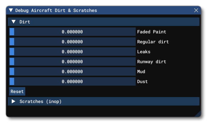
If everything has been setup correctly then moving the different sliders will show / hide the different types of dirt layers on the aircraft:

If you find that there is an issue, you can go to the Behaviors Debug window and select the package and part that you want to debug. You then go to the Visibility tab and find the behavior that you want to check. You can right-click on the Current Value part and bring up a slider so you can force a value and check if it works. This is the best way to check individual meshes, rather than all of them:
