CREATING HANGER / SHOWCASE RTC'S
In this tutorial, we will show you how to create cameras for the aircraft showcase in the Hangar view, which will include Airframe cameras and Cockpit cameras. To create these showcase cameras, you should have a clear idea of what you need to show and a good knowledge of the aircraft specifics and details, as each camera you create will be unique to the aircraft it is showcasing.
NOTE: This tutorial will be done using 3DsMax to create the camera animation, however you can use Blender too.
Airframe Cameras
For the airframe we will need to create at least two scenes in 3DsMax. One (or more) will be the scene for distanced cameras which show off the whole aircraft, it's silhouette and it's general forms, and the other one will be for close-in cameras that show details, zoom in on specifics, and for generally more "artistic" cameras. When creating these scenes you can name them what you want, but we suggest using "sensible" names that you will remember and that make logical sense as they will be important later.
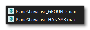
Go ahead and create these scenes now and then save them out. In this example we're saving out PlaneShowcase_GROUND (for far cameras) and PlaneShowcase_HANGAR (for details):
For this tutorial we'll be using the Husky A1C aircraft. Its worth noting that this aircraft has many variations - with skis, with landing gear, and with floats - and it also have two sizes of wheels for the landing gear. With an aircraft like this you would create your RTC's for the initial variation and then save them. You would then create variations of the camera scenes for each specific model of the aircraft, since an aircraft with a tail wheel won't have the same "at rest" position in the simulation nor in the 3DsMax scene. We won't be making those additional scenes in this tutorial, but it's something to keep in mind for your own aircraft.
We'll now go ahead and start creating animations for the PlaneShowcase_GROUND scene. To start with, you'll need to import the airframe model of the aircraft. On import, the aircraft will be parallel with the editor grid and in the center of the scene. It is worth noting that in the simulation, the tail wheel will be align with front wheels on the ground and so the nose of the airframe will be a little bit raised. This should be kept in mind if you animate cameras.
After import you need to do the following:
- Delete all animations and bones.
- Group all meshes in a layer called GEO.
- Ensure that the model is in the correct position, ie: in the same position as in the original airframe model scene.
- Freeze the GEO layer to prevent further interaction.
At the end, you should have something like this:
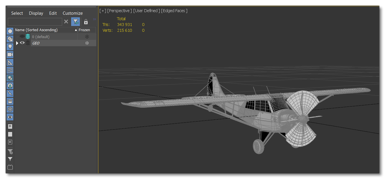
For the next part, you should make a new layer and call it CAMERAS. Now, to create the camera itself, you have two options:
- Create a camera from the perspective view. In 3DsMax this can be done using
Ctrl+Cto create a physical camera, which will have a Target. - Create a camera from the Create menu in 3DsMax. When creating the camera in this way you must chose the Target camera and place it in the scene.
As you may notice, it is very important that any cameras that you create have a target. This is because the target will be exported along with the camera and are actually used in the simulation as part of the blur effect calculations.
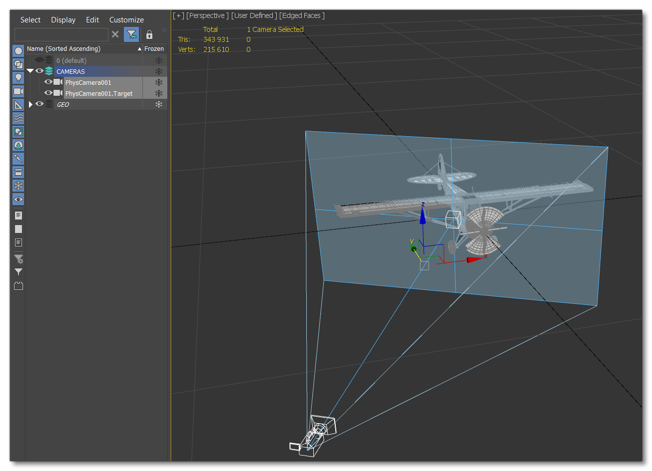
Now you need to animate the camera. For the showcase, you can animate your camera more-or-less any way you want, although it is usually better to have a slow movements without rotation - just focusing on translations of the camera and the target. We also recommend that you have at least 140-160 frames, although more is fine too.
With that done, you will need to rename the camera following this pattern:
<PlaneName>_<variation>_<CameraName>_CAMERA
This will cause the target to be renamed too, however this will not be correct for what we need either. You will need to rename the target following this pattern:
<PlaneName>_<variation>_<CameraName>_TARGET.
IMPORTANT! Ensure that you keep exactly the same name as the camera linked to the target!
To give an example using the Husky, we'd have the following for the camera:
Husky_FrontLeftPanorama_CAMERA
And for the target we'd have this:
Husky_FrontLeftPanorama_TARGET

At this point you can go ahead and create further cameras for the GROUND scene, following the rules outlined above, and showcasing the aircraft from a distance.
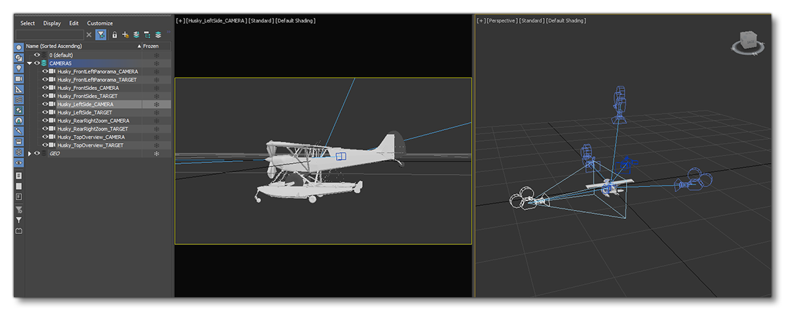
Now you have created your first camera(s) you'll need to ensure that a couple of things are set up correctly before actually rendering it out. To start with, check that the camera animates within the "Safe Frame" space. In 3DsMax this can bone using Shift+F. If everything is correct then you'll next need to ensure that the render setup is correct, as it needs to be set to HDTV (video) in 1920x1080. In 3DsMax you can find this from the Rendering > Render Setup window, under the Common tab:
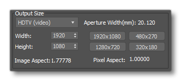
This process is the exact same for the aircraft details and can be replicated for the PlaneShowcase_HANGAR scene, obviously with the emphasis on close-in shots to showcase the aircraft components and specifics.
Cockpit Cameras
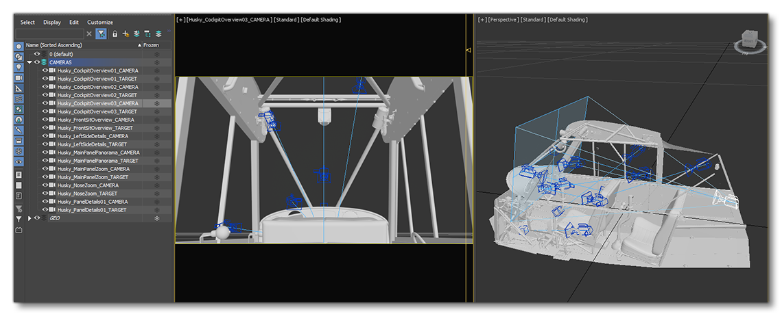
For the cockpit camera, the process is almost exactly the same as that for the airframe. To start with you'll follow these steps:
- Make a new scene and save it as something like
PlaneShowcase_COCKPIT. - Import the cockpit model for the aircraft.
- Delete the animations and bones and then group all the meshes in a layer called GEO.
- Ensure that the model is correctly placed in the scene with reference to the position of the cockpit in the original Cockpit Model scene.
- When you're happy with the position and everything else, freeze the layer to be sure you can't interact with it by mistake.
With that done, you can go ahead and create cameras and targets and animate them as explained for the airframe (minimum 140-160 frames, slow movements, no rotation, render settings to HDTV (video) in 1920x1080, etc...).
When it comes time to rename the camera(s) and targets, you should follow this pattern:
<PlaneName>_<variation>_<CameraName>_CAMERA
<PlaneName>_<variation>_<CameraName>_TARGET
For example:
Husky_MainPanelPanorama_CAMERA
Husky_MainPanelPanorama_TARGET
Exporting
Each scene that you have created will need to be exported, and each one will follow the same process, starting with setting up the Babylon animation group. For that you should open the scene then right-click in the viewport and select Babylon > Babylon Animation Groups. In this window you need to create a new animation group, and then rename it with the name of one camera, but without the CAMERA at the end of the name.
For example, for the airframe we've created above we have a camera called Husky_FrontLeftPanorama_CAMERA, so we'd create an animation group for this camera and rename it Husky_FrontLeftPanorama. In this animation group, you would then add the CAMERA and the TARGET corresponding to the name of the animation group. Once that's done, you would need to set the start and end frames, then click the Confirm button to save the animation.
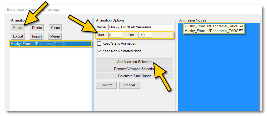
You need to make a unique animation group for each CAMERA/TARGET pair before continuing. When that's all done, we can set up the actual exporter. How you do this will depend on which tool you use: the multi-exporter or the Babylon exporter. Both are explained in the following sections.
However, before looking at the exporters you should take a moment to create the folders that will receive the exported files. This should be made in the same folder that you have made to store the final aircraft files, and the folder needs to be called "RTC". For example:

In this new folder, You need to create two further folders called "animations" and "definitions". In the "animations" folder, we'll be storing all the RTC glTF files for the aircraft, and in the "definitions" folder we'll be storing the RTC XML files for the aircraft.
Multi-exporter
Now you've created all the required folders to store the files we'll be creating, you can open the multi-exporter, available from the FlightSim menu in 3Ds Max. Once in the multi-exporter, you should create a new exporter preset, available from the "Presets" tab. Clicking the Add Preset button will open a file explorer window and you should browse to and select the "animations" folder you made previously.
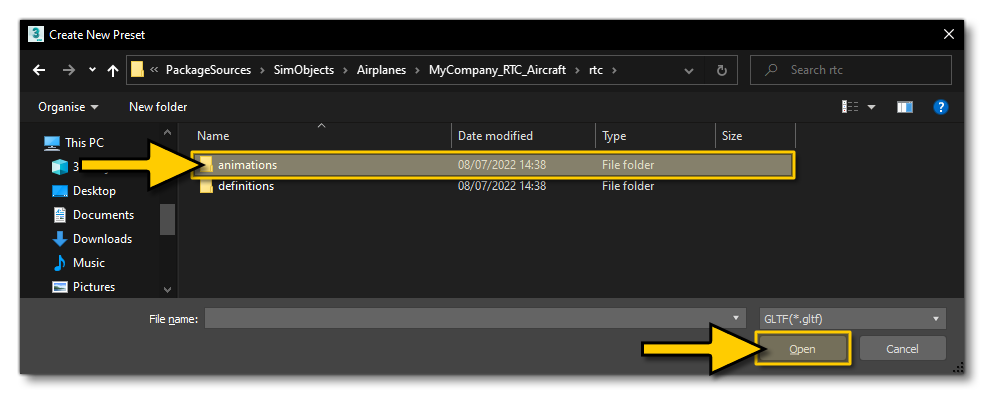
Once the folder has been selected, you can give the preset a name. This name needs to match the name of the scenes you previously created, ie:
PlaneShowcase_GROUND
PlaneShowcase_HANGAR
PlaneShowcase_COCKPIT
Now you can select the preset and in the Layers view, check just the CAMERAS layer.

The next thing to do is set up the Options for the multi-exporter, so click the Options button and in the window you need to do the following:
- Make sure that "Autosave 3ds Max file" is checked.
- Make sure that "Animation" is set to "Export".
- Make sure that "Use Pre-Export Process is un-checked.
- Check the Advanced tab and ensure that nothing has been checked in the "glTF" section.
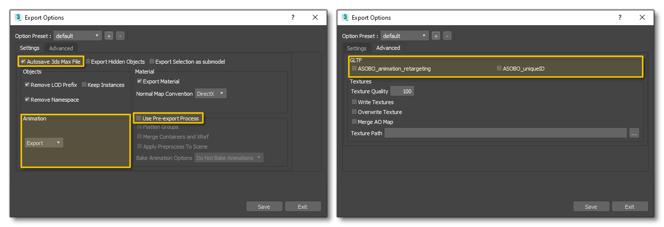
With all that set up, you can then close the Options and click on the Export Preset button to finalise the export. Do the same thing for the other scenes (the Hangar and the Cockpit).
Babylon Exporter
Having created all the scenes, cameras and the required folders for the RTCs, you can export them using the Babylon File Exporter, which can be opened from the Babylon menu in 3Ds Max. With this window open you need to set the model path, giving the path of the folder animations and then name the preset, ensuring that the name matches the name of the scenes you previously created, ie:
PlaneShowcase_GROUND
PlaneShowcase_HANGAR
PlaneShowcase_COCKPIT
Within the window you need to also setup the following:
- Set the "Output Format" to glTF.
- Check the "Auto save 3ds Max file" checkbox.
- Check the "Export only selected" checkbox.
- Uncheck the "Use PreExport Process" checkbox.
- Uncheck the "ASOBO_animation_retargeting" and "ASOBO_uniqueID" options.
- Set the "Animations" section to be "Export".
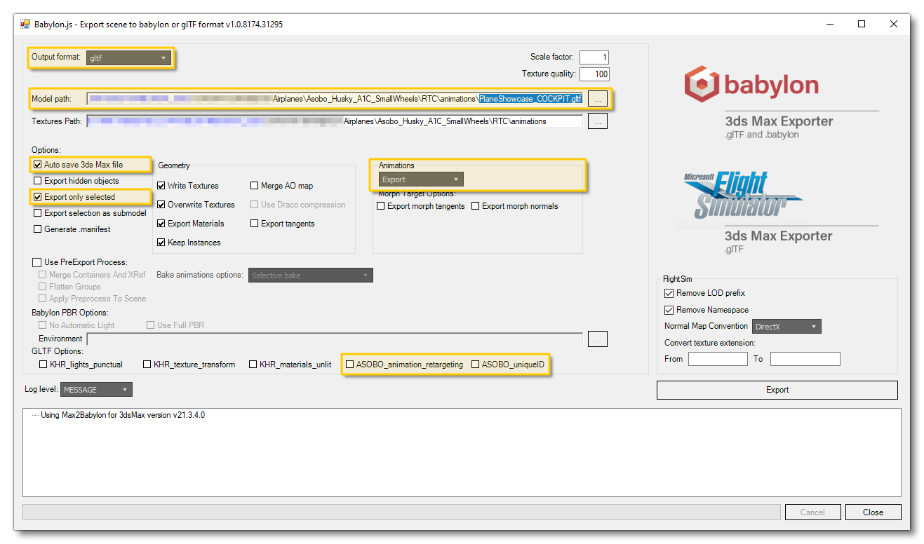
At this point you should select all the cameras and targets in the scene then click on the Export button. Do the same thing for the other scenes (the Hangar and the Cockpit).
Creating The RTC XML FIles
Now to start the tricky part of the RTC pipeline! Those animations you've created and saved as glTF won't do anything unless we have accompanying XML files that tell Microsoft Flight Simulator 2024 what to do with them. So, we're going to go through the steps required to create the XML from scratch, creating the file to accompany the Hangar glTF. Note that we won't be going into much depth here about the different XML elements and attributes... just the most important points. For full information on the elements, please see the following page:
Create The File
In the "definitions" folder you created earlier in this tutorial you need to create a file called RTC_Hangar.xml. With this file open in your preferred editor, add in the following lines:
"<?xml version='1.0' encoding='us-ascii'?>
<SimBase.Document Type="RTC_<AIRCRAFT>" version="1,0">
</SimBase.Document>
We'll also add in the main container element for the RTC's and close off the file, like this:
"<?xml version='1.0' encoding='us-ascii'?>
<SimBase.Document Type="RTC_<AIRCRAFT>" version="1,0">
</SimBase.Document>
    <WorldBase.Flight>
    </WorldBase.Flight>
</SimBase.Document>
Add A Sequencer
So in this element, we going to create our first mission <RTCSequencer>. This <SimMission.RTCSequencer> will do the transition between the time when we select the plane in the Hangar, and all our Cameras animations for the Showcase. For the <SimMission.RTCSequencer>, we will need a unique GUID, so generate the GUID and add it into the element as the InstanceID, like this :
<?xml version='1.0' encoding='us-ascii'?>
<SimBase.Document Type="RTC_<AIRCRAFT>" version="1,0">
	<WorldBase.Flight>
		<SimMission.RTCSequencer InstanceId="{D712985B-AE7E-4622-A117-DA66226D5E50}">
		</SimMission.RTCSequencer>
	</WorldBase.Flight>
</SimBase.Document>
NOTE: Information on generating GUIDs can be found here - GUIDs.
In the <SimMission.RTCSequencer> we will always need additional elements to set up the Sequencer correctly (see here for more information), but we don't actually need to use all of the available ones. For this first <SimMission.RTCSequencer>, we suggest that you just copy the same elements we've added in the example below, and then modify them if needed (for example, by changing the description) :
<?xml version='1.0' encoding='us-ascii'?>
<SimBase.Document Type="RTC_<AIRCRAFT>" version="1,0">
    <WorldBase.Flight>
        <SimMission.RTCSequencer InstanceId="{D712985B-AE7E-4622-A117-DA66226D5E50}">
            <Descr>AIRCRAFT_Hangar</Descr>
            <NeedPreload>True</NeedPreload>
            <Shuffle>False</Shuffle>
            <LoopAnimation>False</LoopAnimation>
            <Actions>
            </Actions>
            <IsHangarCamera>True</IsHangarCamera>
        </SimMission.RTCSequencer>
    </WorldBase.Flight>
</SimBase.Document>
You can see that in the example above we've added in the <Actions> element. With this element, we will call 2 other <SimMission.RTCSequencer>: one for the small camera animation between Menu To Hangar, and the other one for our Hangar animation. These 2 new sequencers will also need 2 new GUID. We can call those RTCSequencer with <SimMission.ObjectReference /> elements, which would be added to the the XML, as shown below:
<?xml version='1.0' encoding='us-ascii'?>
<SimBase.Document Type="RTC_<AIRCRAFT>" version="1,0">
    <WorldBase.Flight>
        <SimMission.RTCSequencer InstanceId="{D712985B-AE7E-4622-A117-DA66226D5E50}">
            <Descr>AIRCRAFT_Hangar</Descr>
            <NeedPreload>True</NeedPreload>
            <Shuffle>False</Shuffle>
            <LoopAnimation>False</LoopAnimation>
            <Actions>
                <SimMission.ObjectReference id="AIRCRAFT_MenuToHangar" InstanceId="{C1980794-F1D9-4eca-B7AF-DE3A138CC620}"/>
                <SimMission.ObjectReference id="AIRCRAFT_HangarAnimation" InstanceId="{B0823935-D117-4542-8047-981E6ACEDFE0}"/>
             </Actions>
             <IsHangarCamera>True</IsHangarCamera>
        </SimMission.RTCSequencer>
    </WorldBase.Flight>
</SimBase.Document>
Add Initial Sequence Objects
Now we can go ahead and create the first of those sequencer objects that we have referenced in the XML: AIRCRAFT_MenuToHangar. This is done exactly the same way as we did for the main sequencer, by adding the description, preload, etc... elements. Also, don't forget to assign it the same GUID that was used by the ObjectReference in the main sequencer. The XML will now be like this:
<?xml version='1.0' encoding='us-ascii'?>
<SimBase.Document Type="RTC_<AIRCRAFT>" version="1,0">
    <WorldBase.Flight>
        <SimMission.RTCSequencer InstanceId="{D712985B-AE7E-4622-A117-DA66226D5E50}">
            <Descr>AIRCRAFT_Hangar</Descr>
            <NeedPreload>True</NeedPreload>
            <Shuffle>False</Shuffle>
            <LoopAnimation>False</LoopAnimation>
            <Actions>
                <SimMission.ObjectReference id="AIRCRAFT_MenuToHangar" InstanceId="{C1980794-F1D9-4eca-B7AF-DE3A138CC620}"/>
                <SimMission.ObjectReference id="AIRCRAFT_HangarAnimation" InstanceId="{B0823935-D117-4542-8047-981E6ACEDFE0}"/>
            </Actions>
            <IsHangarCamera>True</IsHangarCamera>
        </SimMission.RTCSequencer>
        <SimMission.RTCSequencer InstanceId="{C1980794-F1D9-4eca-B7AF-DE3A138CC620}">
            <Descr>AIRCRAFT_MenuToHangar</Descr>
            <NeedPreload>True</NeedPreload>
            <ReuseSameCycle>False</ReuseSameCycle>
            <RTCSequence>
                <ShotCount>1</ShotCount>
                <Shuffle>True</Shuffle>
                <AnimationToInclude>HangarTransition</AnimationToInclude>
                <ShotType>Aircraft</ShotType>
                <DepthOfField>
                    <!-- <Activate>True</Activate> -->
                    <!-- <Blur>0.2</Blur> -->
                    <ApplyFrontFocus>True</ApplyFrontFocus>
                </DepthOfField>
            </RTCSequence>
        </SimMission.RTCSequencer>
    </WorldBase.Flight>
</SimBase.Document>
You can see that in our new <SimMission.RTCSequencer> we've added a single <RTCSequence> which has the <ShotCount> element set to 1. This element is used to tell the sequencer that the sequence we're creating contains just a single animation. The other elements are fairly self-explanatory, but it's worth giving a special mention to the <AnimationToInclude> element. This must be set to HangarTransition, as without that you won't have the right animation used for the transition between menu and hangar. The element <ShotType> also requires a mention, as it must also be set to Aircraft, otherwise the animation won't play correctly around the loaded aircraft.
Now we can create the second RTCSequencer for Hangar animations that we created at the start of the tutorial. In this Sequencer we will reference animations for the airframe and animations for the cockpit in 2 different sequencers. Here's the finished XML, which we'll discuss:
<?xml version='1.0' encoding='us-ascii'?>
<SimBase.Document Type="RTC_<AIRCRAFT>" version="1,0">
    <WorldBase.Flight>
        <SimMission.RTCSequencer InstanceId="{D712985B-AE7E-4622-A117-DA66226D5E50}">
            <Descr>AIRCRAFT_Hangar</Descr>
            <NeedPreload>True</NeedPreload>
            <Shuffle>False</Shuffle>
            <LoopAnimation>False</LoopAnimation>
            <Actions>
                <SimMission.ObjectReference id="AIRCRAFT_MenuToHangar" InstanceId="{C1980794-F1D9-4eca-B7AF-DE3A138CC620}"/>
                <SimMission.ObjectReference id="AIRCRAFT_HangarAnimation" InstanceId="{B0823935-D117-4542-8047-981E6ACEDFE0}"/>
            </Actions>
            <IsHangarCamera>True</IsHangarCamera>
        </SimMission.RTCSequencer>
        <SimMission.RTCSequencer InstanceId="{C1980794-F1D9-4eca-B7AF-DE3A138CC620}">
            <Descr>AIRCRAFT_MenuToHangar</Descr>
            <NeedPreload>True</NeedPreload>
            <ReuseSameCycle>False</ReuseSameCycle>
            <RTCSequence>
                <ShotCount>1</ShotCount>
                <Shuffle>True</Shuffle>
                <AnimationToInclude>HangarTransition</AnimationToInclude>
                <ShotType>Aircraft</ShotType>
                <DepthOfField>
                    <!-- <Activate>True</Activate> -->
                    <!-- <Blur>0.2</Blur> -->
                    <ApplyFrontFocus>True</ApplyFrontFocus>
                </DepthOfField>
            </RTCSequence>
        </SimMission.RTCSequencer>
        <SimMission.RTCSequencer InstanceId="{B0823935-D117-4542-8047-981E6ACEDFE0}">
            <Descr>AIRCRAFT_HangarAnimation</Descr>
            <NeedPreload>True</NeedPreload>
            <Shuffle>False</Shuffle>
            <LoopAnimation>True</LoopAnimation>
            <ReuseSameCycle>False</ReuseSameCycle>
            <Actions>
                <SimMission.ObjectReference id="AIRCRAFT_AIRFRAME" InstanceId="{D6EE186A-7BF9-414c-964A-8C73E3028CF7}"/>
                <SimMission.ObjectReference id="AIRCRAFT_COCKPIT" InstanceId="{B9A92980-AB81-469a-9310-D8C573934CAC}"/>
            </Actions>
        </SimMission.RTCSequencer>
    </WorldBase.Flight>
</SimBase.Document>
With this addition we have created another sequencer that references two further RTC sequences which we will need to create. Things to note in this XML that we just added:
- The
<LoopAnimation>element is used to make the animation loop infinitely. - The
<ReuseSameCycle>element is used to make the animation always play the airframe first and the cockpit second.
Creating The Final Sequences
Having done all the preparation, you can go ahead and add in the final two sequences for showcasing the airframe and the cockpit:
<?xml version='1.0' encoding='us-ascii'?>
<SimBase.Document Type="RTC_<AIRCRAFT>" version="1,0">
    <WorldBase.Flight>
        <SimMission.RTCSequencer InstanceId="{D712985B-AE7E-4622-A117-DA66226D5E50}">
            <Descr>AIRCRAFT_Hangar</Descr>
            <NeedPreload>True</NeedPreload>
            <Shuffle>False</Shuffle>
            <LoopAnimation>False</LoopAnimation>
            <Actions>
                <SimMission.ObjectReference id="AIRCRAFT_MenuToHangar" InstanceId="{C1980794-F1D9-4eca-B7AF-DE3A138CC620}"/>
                <SimMission.ObjectReference id="AIRCRAFT_HangarAnimation" InstanceId="{B0823935-D117-4542-8047-981E6ACEDFE0}"/>
            </Actions>
            <IsHangarCamera>True</IsHangarCamera>
        </SimMission.RTCSequencer>
        <SimMission.RTCSequencer InstanceId="{C1980794-F1D9-4eca-B7AF-DE3A138CC620}">
            <Descr>AIRCRAFT_MenuToHangar</Descr>
            <NeedPreload>True</NeedPreload>
            <ReuseSameCycle>False</ReuseSameCycle>
            <RTCSequence>
                <ShotCount>1</ShotCount>
                <Shuffle>True</Shuffle>
                <AnimationToInclude>HangarTransition</AnimationToInclude>
                <ShotType>Aircraft</ShotType>
                <DepthOfField>
                    <!-- <Activate>True</Activate> -->
                    <!-- <Blur>0.2</Blur> -->
                    <ApplyFrontFocus>True</ApplyFrontFocus>
                </DepthOfField>
            </RTCSequence>
        </SimMission.RTCSequencer>
        <SimMission.RTCSequencer InstanceId="{B0823935-D117-4542-8047-981E6ACEDFE0}">
            <Descr>AIRCRAFT_HangarAnimation</Descr>
            <NeedPreload>True</NeedPreload>
            <Shuffle>False</Shuffle>
            <LoopAnimation>True</LoopAnimation>
            <ReuseSameCycle>True</ReuseSameCycle>
            <Actions>
                <SimMission.ObjectReference id="AIRCRAFT_AIRFRAME" InstanceId="{D6EE186A-7BF9-414c-964A-8C73E3028CF7}"/>
                <SimMission.ObjectReference id="AIRCRAFT_COCKPIT" InstanceId="{B9A92980-AB81-469a-9310-D8C573934CAC}"/>
            </Actions>
        </SimMission.RTCSequencer>
        <SimMission.RTCSequencer InstanceId="{D6EE186A-7BF9-414c-964A-8C73E3028CF7}">
            <Descr>AIRCRAFT_AIRFRAME</Descr>
            <NeedPreload>True</NeedPreload>
            <Shuffle>True</Shuffle>
            <ReuseSameCycle>False</ReuseSameCycle>
            <ShotCount>5</ShotCount>
            <RTCSequence>
                <ShotType>Aircraft</ShotType>
                <Shuffle>True</Shuffle>
                <FileToInclude>PlaneShowcase_GROUND</FileToInclude>
                <FileToInclude>PlaneShowcase_HANGAR</FileToInclude>
                <DepthOfField>
                    <Activate>True</Activate>
                    <Blur>0.15</Blur>
                </DepthOfField>
            </RTCSequence>
        </SimMission.RTCSequencer>
        <SimMission.RTCSequencer InstanceId="{B9A92980-AB81-469a-9310-D8C573934CAC}">
            <Descr>AIRCRAFT_COCKPIT</Descr>
            <NeedPreload>True</NeedPreload>
            <Shuffle>True</Shuffle>
            <ReuseSameCycle>False</ReuseSameCycle>
            <ShotCount>4</ShotCount>
            <RTCSequence>
                <ShotType>Aircraft</ShotType>
                <Shuffle>True</Shuffle>
                <FileToInclude>PlaneShowcase_COCKPIT</FileToInclude>
            </RTCSequence>
        </SimMission.RTCSequencer>
    </WorldBase.Flight>
</SimBase.Document>
By now, you should be familiar with the structure of the sequencer and the way shots are created, however we should point out the use of the <FileToInclude> element, which is what you must use to call the glTF file that we created at the start of this tutorial.
Testing
Having created the XML file, you will now need to save it to the appropriate location, which should be in the "definitions" folder that you created previously, within the RTC folder for the aircraft:

Once the file is saved, you need to go into the simulation and open the package in the Project Editor, then build the package. Once the package is rebuilt, you'll need to exit and restart the simulation for the changes to the camera to be visible. Once restarted, simply go to the hangar and select the aircraft and you should be presented with the RTCs that you have created to showcase the aircraft.