
engines.cfg
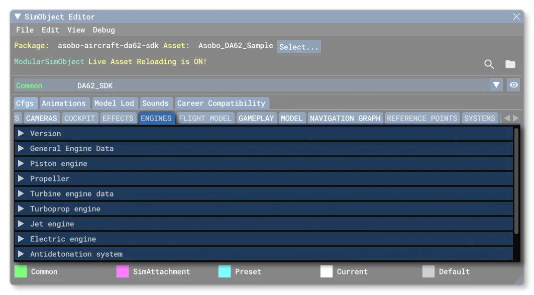
The engines.cfg file is an optional file for SimObjects, unless you are creating an aircraft in which case it is mandatory. This file is used for defining the behavior and characteristics of the aircraft engines. Below you can find information on the different sections used in the engines.cfg file as well as what parameters and values are expected within them.
to help with the configuration of the Engine CFG file (and the flight_model.cfg) we have included an *.xlsx file with the documentation that can be used to generate the required values for many of the parameters based on a small number of inputs (these inputs are marked in blue in the file):
Additionally you have access to the MSFS Turbojet Static Performance Tool which can be used for tuning turbine engine parameters.
[Version]
The [Version] section provides version information for the configuration file. In Microsoft Flight Simulator 2024, major versions should always be at least equal to 1.
Note that this section information is mandatory and should always be included.
| Parameter | Description | Type | Required |
|---|---|---|---|
major | Major CFG file version number, values must be greater than 0. | Integer | Yes |
minor | Minor CFG file version number, values must be greater than 0. | Integer | Yes |
[GENERALENGINEDATA]
Every type of aircraft, even a glider, should have this section in the engines.cfg file. Basically, this section describes the type of engine, the number of engines, where the engines are located, and a fuel flow scalar to modify how much fuel the engine requires to produce the calculated power. The parameters available are:
| Parameter | Description | Type | Required |
|---|---|---|---|
engine_type | Value that identifies what type of engine is on the aircraft. | Integer: 0 = Piston 1 = Jet 2 = None 3 = Helo-turbine 4 = Rocket (not supported) 5 = Turboprop. 6 = Electric | Yes |
fuel_flow_scalar | This is a scalar value for modifying the fuel flow required by the engine(s) with an impact on the rate at which fuel tanks empty only. Allows you to easily adjust the fuel consumption of the engine without changing any other aspect. A value of less than 1.0 causes a slower fuel consumption for a given power setting, a value greater than 1.0 causes the aircraft to burn more fuel for a given power setting.Please note that the actual fuel flow will depend on whether you have included the fuel_flow_scalar_idle parameter or not. | Float | Yes |
fuel_flow_scalar_idle | if this parameter is defined, instead of using only the existing fuel_flow_scalar parameter, the simulation will take the current throttle position, and use that to create a linear interpolation between the fuel_flow_scalar and the fuel_flow_scalar_idle parameters.For example, if the throttle is 40% of the way between idle and max, then the actual fuel flow scalar used will be the interpolated value 40% of the way between the fuel_flow_scalar and the fuel_flow_scalar_idle values.If not defined then the fuel_flow_scalar parameter will be used. | Float | No |
min_fuel_press_for_combustion_psf | The minimum fuel pressure required to get a combustion (in psf).Default is 0.01. | Float | No |
min_throttle_limit | This value defines the minimum throttle position (as a percentage of the maximum). Value is expressed between -1.0 and 1.0, where a negative value is for engines with a reverse mode. Normally this is 0 for piston aircraft and -0.25 for turbine airplane engines with reverse thrust.For more information, please see the Note On Propeller Pitch And Throttle.IMPORTANT! If either corrected_commanded_Ne_table or uncorrected_commanded_Ne_table is defined, then this parameter will no longer affect commanded Ne (or corrected commanded Ne), but it may still be used in other engine performance calculations. | Float | Yes |
master_ignition_switch | Defines whether the master ignition switch is available (1, TRUE) or not (0, FALSE). If available, this switch must be on for the ignition circuit, and thus the engines, to be operable. Turning it off will stop all engines.Default is 0 (FALSE). | Bool | No |
starter_type | The engine starter type.Default is 0. | Integer: 0 = Electric 1 = Manual 2 = Bleed Air | No |
requires_priming | If set to 1 (TRUE), the engine may need to be primed before combustion (depending on temperature). Set to 0 (FALSE) otherwise.Default is 0 (FALSE). | Integer | No |
max_contrail_temperature | The ambient temperature below which engine vapor contrails will be turned on. For piston engines, the contrail effect is turned off unless a temperature value is set here, and for turbine engines the effect will occur automatically.Default is -39.724 (for turbine engines above 27,362 ft), or set to -1 for no contrails. | Float | Yes |
accumulated_time_hobbs_min_pct_rpm | This can be used to configure the percentage RPM threshold of detection for measuring how long the engine has been running.Default is -1 (ie: no threshhold). | Float | No |
accumulated_time_hobbs_min_knots | This can be used to configure the airspeed threshold of detection for measuring how long the engine has been running.Default is 25 Knots. | Float | No |
Engine.N | Offset of the engine N thrust position from the Datum Reference Point. Each position takes a list of three values: - z (longitudinal distance) - x (lateral distance) - y (vertical distance)Each location N specified increases the engine count (maximum of 16 engines allowed i.e: N is between 0 and 15), and all values are specified in ft. For propeller/turboprop aircraft, this point of thrust is where the propeller is on the engine, and for jet engines, it’s the point of thrust output for the engine.Note that these coordinates are important as they impact the rotation moments generated by engine thrust and will also impact the location of engine wash.Default is 0, 0, 0. | List of 3 Floats | Yes |
smoke_protection | This parameter can be used to prevent smoke doing any damage to the engines. Setting it to 1 (true) enables smoke protection and setting it to 0 (false) will disable it and engines will take damage when flying through smoke. For more information, please see here: Note On Collision Damage / Wear And TearDefault value is 0. | Bool | No |
ThrustAnglesPitchHeading.N | Thrust pitch and heading angles (in degrees) for engine number N, expressed as two values: - Value 1 is the pitch (theta x) where: - <0° is pitch down - >0° is pitch up - Value 2 is the heading (theta y) where: - <0° is heading left - >0° is heading right.This will affect the direction of thrust for the engine.Default is 0, 0. | List of 2 Floats | No |
TiltMinAngles.N | The minimum pitch and yaw angles - in degrees - that engine N can tilt, relative to the corresponding ThrustAnglesPitchHeading.N. These values will be used as the minimum values for changing the orientation (tilting) of the engine during flight.Default is 0, 0 (pitch, yaw). | List of 2 Floats | |
TiltMaxAngles.N | The maximum pitch and yaw angles - in degrees - that engine N can tilt, relative to the corresponding ThrustAnglesPitchHeading.N. These values will be used as the minimum values for changing the orientation (tilting) of the engine during flight.Default is 0, 0 (pitch, yaw). | List of 2 Floats |
[PISTON_ENGINE]
This section is for defining the qualities of the piston engine of an aircraft. In general, the engines of an aircraft should be created and edited through the SimObject Editor, and only tweaked if required through the engines.cfg file. If the aircraft being defined has no piston engines this section can be omitted.
This section is not required if you are creating a Helicopter SimObject.
You can also find a helpful tutorial on the basics of setting up the aircraft engines from the following page:
A piston engine’s power can be determined through a series of equations that represent the Otto cycle of a four-stroke piston engine, multiplied by the number of pistons available. This section contains all the information needed to be able to determine how much power the engines are capable of producing. Power can also be scaled from the calculated values generated for piston engines with the power_scalar property.
The available parameters in the [PISTON_ENGINE] section are:
| Parameter | Description | Type | Required |
|---|---|---|---|
cylinder_displacement | Cylinder displacement for each cylinder in cubic inches. This will affect the cylinder torque. | Float | Yes |
compression_ratio | The compression ratio of each cylinder. This will affect the cylinder torque. | Float | Yes |
number_of_cylinders | Engine cylinder count. Will affect the total torque sum of all cylinder torques and the total engine friction of all cylinders. | Integer | Yes |
max_rated_rpm | The maximum rated RPM of the piston engine. Should be set to the actual aircraft max rated rpm and should not be used to tweak engine performance. | Float | Yes |
max_rated_hp | The maximum rated power of the piston engine. Should be set to the actual aircraft max rated power and not be used to tweak engine performance. This value is affected by the power_scalar. Has a direct impact on fuel flow but no direct impact on engine torque or output power. The output power needs to be adjusted to actually meet this value, as it won’t be met automatically. | Float | Yes |
power_scalar | Scalar used to ponderate the max_rated_hp value, scaling the net torque / power output of the engine that is transferred to the propeller.Here is a simplified formula to understand the engine torque output:$$Torque = power\_scalar \times \Bigl( (CylinderTorque \times MechanicalEfficiency) - (CylinderFriction \times OilViscosity) \Bigr)$$This formula allows to understand how the power_scalar affects the net output.Default is 1.0. | Float | No |
two_stroke_cycle | Sets whether the engine is a two stroke cycle engine (TRUE, 1) or not (FALSE, 0).Default value is 0 (FALSE). | Bool | No |
carb_icing_sensiblity | How sensitive the carburetor is to icing.Default value is 0.25. | Float | No |
starter_time | Time (in seconds) during which the starter will be enabled when toggled on.Default is 1.5 seconds. | Float | No |
max_design_mp | This parameter works in two “modes” depending on whether the turbocharged parameter is set to TRUE or not. When set to TRUE, this value indicates the maximum design manifold pressure supplied by the turbocharger, in inHg. When turbocharged is set to FALSE, this sets the value the manifold pressure regulator should not exceed (essentially the maximum value the regulator will authorize), in inHg.Default value is 0. | Float | No |
min_design_mp | If a turbocharger is present, this value indicates the minimum design manifold pressure supplied by the turbocharger, in inHg.Default value is 0. | Float | No |
normalized_starter_torque | This value can be modified to increase/decrease the torque supplied by the starter to get the prop turning. Increase this value for a greater torque effect, decrease it for a lower torque setting, and the value cannot go below 0, and is usually less than 1.Default value 0.3. | Float | No |
auto_ignition | Sets whether auto-ignition is available (TRUE, 1) or not (FALSE, 0). When auto ignition is absent, magnetos need to be enabled for the engine to function. With auto ignition, there is no need to enable magnetos.Default value is 0 (FALSE). | Bool | No |
shaft_torque_tc | Gives the speed at which the shaft torque reaches its target value (not applicable for legacy FSX aircraft).See the Note On Time Constants And Tuning Constants for additional information.Default value is 2. | No | |
carb_heat_delta_temp | Gives the delta of temperature - in Rankine - when the carburetor Heater is activated.Default value is 27. | Float | No |
induction_air_temp_tc | Give the speed at which the Induction Air Temp increases to reach it’s target value.See the Note On Time Constants And Tuning Constants for additional information.Default value is 0.7. | Float | No |
cooling_type | An integer value indicating the method of engine cooling.Default value is 0. | Integer: 0 = air cooled 1 = liquid cooled | No |
emergency_boost_type | Integer value indicating the emergency boost type available. The emergency boost system was originally designed to model the systems used on WWII aircraft, however it also models water/methanol systems available for more modern aircraft, and is a way to generate a power setting that is actually above the max continuous rating of the engine.Default value is 0 (none). | Integer: 0 = None 1 = Water Injection 2 = Methanol/Water Injection 3 = WEP | No |
max_emergency_boost_time | The emergency boost duration (in seconds) When this time has elapsed, the engine will be considered as “damaged” and have greatly reduced power.Please see the Notes On Emergency Boost for more information.If not specified, the default values are 315 seconds for WEP and 312 seconds for methanol-water injection. | Float | No |
emergency_boost_mp_offset | Additional manifold pressure supplied by emergency boost, if available. Value is in inHg.Default value is 0. | Float | No |
emergency_boost_mp_damage | Defines the manifold pressure above which - when emergency boost is activated and running - the simulation will start measuring how much time you spent with emergency boost running until you reach the time limit. Value is in inHg.Please see the Notes On Emergency Boost for more information.Default value is 0. | Float | No |
emergency_boost_gain_offset | Multiplier on manifold pressure due to emergency boost. Value must be greater than 0.0 to have any effect.Default value is 0. | Float | No |
emergency_boost_can_be_stopped | Controls whether or not the Emergency Boost can be shut down after it is engaged.Default value is 1 (TRUE). | Bool | No |
emergency_boost_throttle_threshold | Threshold at which the emergency boost will boost the engine. This is semi-automatic and will first require that the user activates war emergency power using the simulation input controls (key/gamepad/controller), and then emergency boost will activate when the throttle goes above the threshold set here. Note that this value is only relevant when the emergency_boost_type parameter is set to 3.The default value is 0.99. | Float | No |
wep_damage_efficiency_factor | This is a factor (expressed as a Percent Over 100) on how much efficiency is affected when WEP is over-used. Value should be greater than 0.Default value is 0.7. | Float | No |
turbocharged | Value to indicate if the engine is turbocharged (TRUE, 1) or not (FALSE, 0). Note that you cannot set this to TRUE if the manifold_pressure_regulator parameter is enabled, as they are mutually exclusive systems.Default is 0 (FALSE). | Bool | No |
density_to_boost_table | Gives the relation between the ambient air density (in slug / ft³) and the volumetric multiplier of maximum displacement at sea level. In other words, this table scales the potential manifold pressure pre-wastegate.For example, if you wanted to double the maximum available manifold pressure at a pressure altitude of 10,000ft (ISA density of 17.56 slug / ft³), you would use the following array: 17.56:2.0Note that this table is only used when the turbocharged parameter is set to 1 (TRUE), and in that case - if this parameter is included - the critical_altitude value will be ignored. There are no default values for this table, and if it is simply omitted from the file, then the critical_altitude parameter will be used. | 1D Curve of Floats | No |
critical_altitude | Altitude, in ft, at which the turbocharger - if present - will provide the maximum design manifold pressure. Above this altitude, the reciprocating engine will no longer produce its rated horsepower even with its throttle wide open.Default value is 0. | Float | No |
supercharged | Sets whether the engine is supercharged (1, TRUE) or not (0, FALSE). If the parameter new_supercharged is set to either 1 or 2, then this parameter should be set to FALSE (0), or be omitted from the CFG file. Please see the Notes On Supercharger section for additional information on this feature.Default value is 0 (FALSE). | Bool | No |
new_supercharged | Set the engine to use the modern supercharger formulas using one of the 2 possible models, or set to 0 to use the legacy version. If set to 1 or 2, the supercharged parameter should be set to 0 or omitted from the CFG file. If set to 0, then the supercharged parameter may be used (although this is only recommended for legacy aircraft). Please see the Notes On Supercharger section for additional information on this feature.Default value is 0 (FALSE). | Enum: 0 = Off. Use for legacy aircraft. 1 = Use a fixed formula to calculate the supercharger boost. 2 = Use for multi speed supercharger support. | No |
supercharger_altitude_gear.N | Gives the pressure altitude (in ft) at which the supercharger gear number N will be engaged. There are a maximum of 5 gears, numbered from 1. This parameter is only used when new_supercharged is set to 2, and also requires that supercharged is set to 0.Default value for each gear is -1. | Float | No |
supercharger_boost_high_end_gear.N | High end boost given by the supercharger when in gear N. There are a maximum of 5 gears, numbered from 1. This parameter is only used when new_supercharged is set to 2, and also requires that supercharged is set to 0.Default value for each gear is 1. | Float | No |
supercharger_boost_low_end_gear.N | Low end boost given by the supercharger when in gear N. There are a maximum of 5 gears, numbered from 1. This parameter is only used when new_supercharged is set to 2, and also requires that supercharged = 0.Default value for each gear is 1. | Float | No |
supercharger_power_cost | Percent of horsepower required to drive supercharger.Default value is 0. | Float | No |
supercharger_boost_low_end | Multiplier on manifold pressure at low RPM. The actual effect will depend on whether new_supercharged is enabled or not. If enabled, then it can ONLY be set to 1 (using 2 won’t work). If supercharged is set to 1 then these parameters are valid, but new_supercharged must be set to 0.Default value is 1. | Float | No |
supercharger_boost_high_end | Multiplier on manifold pressure at high RPM. The actual effect will depend on whether new_supercharged is enabled or not. If enabled, then it can ONLY be set to 1 (using 2 won’t work). If supercharged is set to 1 then these parameters are valid, but new_supercharged must be set to 0.Default value is 1. | Float | No |
manifold_pressure_regulator | Controls whether or not the engine has a manifold pressure regulator (1, TRUE) or not (0, FALSE). This regulator limits the air entering the manifold by opening or closing depending on the pressure need. To replicate this the waste gate is used as a limiting factor on the total boost instead of as a boosting factor like in the turbocharger. That means that the RECIP ENG WASTEGATE POSITION SimVar will fluctuate between 0% and 100%, and can be monitored. The closer it is to 100% the more it limits the boost.Note that you cannot have a manifold pressure regulator if the turbocharged parameter is set to TRUE, as they are mutually exclusive systems.Default value is 0 (FALSE). | Bool | No |
manifold_pressure_regulator_threshold | Manifold pressure (in inHg) at which the Manifold pressure regulator will start having an effect.Default value is 0 inHg. | Float | No |
manifold_pressure_regulator_tc | Manifold pressure time constant.See the Note On Time Constants And Tuning Constants for additional information.Default value is 0.0. | Float | No |
manifold_efficiency_table | Gives the relation between the Throttle input and the effect on manifold - essentially giving a way to change the engine idle RPM. Each element of the the table - up to a maximum of 47 elements - is a point defined by a throttle position and an efficiency “scalar”, so the table should look like this:throttle_pos:manifold_efficiency,throttle_pos:manifold_efficiency,etc...For example:manifold_efficiency_table = 0:0.225, 1:0.97The default values are:manifold_efficiency_table = 0:0.2, 1:0.97 | 1D Curve of Floats | No |
manifold_pressure_correction_by_rpm | With this value you can correct the manifold pressure when the relative RPM does not match the throttle position, multiplying the difference using this coefficient. The value is given in inHg and is not limited.Default value is -2.4885 inHg. | Float | No |
manifold_pressure_min | This value limits the minimum final value of the manifold pressure. The value is given is given in inHg and cannot be negative. Note that the final manifold pressure minimum will depend on atmospheric pressure as well, being whichever of the two is lower: this parameter, or the atmospheric pressure.Default value is 4.949 inHg. | Float | No |
detonation_onset | The manifold pressure (in psi) that if reached or exceeded will lead to the engine detonating.Default value is -1 (disabled). | Float | No |
min_cruise_rpm | The minimum RPM for cruise speed. | Float | Yes |
max_cruise_rpm | The maximum RPM for cruise speed. | Float | Yes |
max_indicated_rpm | The maximum RPM to be shown in the UI RPM indicator instrument. This has no influence on the flight model of the aircraft. | Float | Yes |
min_required_rpm | The minimum required RPM to prevent the engine from shutting down.Default value is 700. | Integer | No |
max_rpm_mechanical_efficiency_scalar | This is a scalar value that can be modified to tune the mechanical efficiency of the engine at maximum RPM. Increase this value to increase the mechanical efficiency, decrease it to decrease the mechanical efficiency. Value must be greater than 0. This is a modifier that will be used along with the engine_mechanical_efficiency_table.This is one of the mechanical efficiency scalars that will be applied to the torque formula:$$Torque = power\_scalar \times \Bigl( (CylinderTorque \times MechanicalEfficiency) - (CylinderFriction \times OilViscosity) \Bigr)$$Default value is 1.0. | Float | No |
idle_rpm_mechanical_efficiency_scalar | This is a scalar value that can be modified to tune the mechanical efficiency of the engine at idle RPM. Increase this value to increase the mechanical efficiency, decrease it to decrease the mechanical efficiency. Value must be greater than 0. This is a modifier that will be used along with the engine_mechanical_efficiency_table.This is one of the mechanical efficiency scalars that will be applied to the torque formula:$$Torque = power\_scalar \times \Bigl( (CylinderTorque \times MechanicalEfficiency) - (CylinderFriction \times OilViscosity) \Bigr)$$Default value is 1.0. | Float | No |
low_rpm_shake_scalar | This scalar value is used to add a realistic shaking motion to piston aircraft based on the number and RPM of the engines.Default value is 1.0. | Float | No |
max_rpm_friction_scalar | This is a scalar value that can be modified to tune the internal friction of the engine at maximum RPM. Increase this value to increase the friction, decrease it to decrease the friction. Value must be greater than 0.This is one of the friction scalars that will be applied to the torque formula:$$Torque = power\_scalar \times \Bigl( (CylinderTorque \times MechanicalEfficiency) - (CylinderFriction \times OilViscosity) \Bigr)$$Default value is 1.0. | Float | No |
idle_rpm_friction_scalar | This is a scalar value that can be modified to tune the internal friction of the engine at idle RPM. Increase this value to increase the friction, decrease it to decrease the friction. Value must be greater than 0.This is one of the friction scalars that will be applied to the torque formula:$$Torque = power\_scalar \times \Bigl( (CylinderTorque \times MechanicalEfficiency) - (CylinderFriction \times OilViscosity) \Bigr)$$Default value is 1.0. | Float | No |
rpm_to_oil_pressure_table | Gives the relation between the percentage maximum RPM and the percentage maximum oil pressure in a table with up to 47 elements. For example:rpm_to_oil_pressure_table = 0:0, 0.1:0.3, 0.2:0.9, 0.519:1, 0.74:1 ;Default values are:rpm_to_oil_pressure_table = 0:0, 0.185:0.3, 0.519:1, 0.740:1 | 1D Curve of Floats | No |
rpm_to_fuel_pressure_table | Gives the relation between the percentage maximum RPM and the percentage maximum fuel pressure in a table with up to a 47 elements. For example:rpm_to_fuel_pressure_table = 0:0, 1000:0.3, 2800:1, 4000:1The formula for calculating the fuel pressure is as follows:$$\text{FuelPress} = \text{fuel\_press\_tuning\_constant} \times \text{fuel\_press\_max} \times \text{rpm\_to\_fuel\_pressure\_table}$$Default values are:rpm_to_fuel_pressure_table = 0.0:0.0, 500.0:0.3, 1400.0:1.0, 2000.0:1.0 | 1D Curve of Floats | No |
rpm_on_cht_table | Gives the relationship between the RPM (as a percentage of maximum) and the cylinder head temperature (as a percentage of maximum) in a table of up to 47 elements. For example:rpm_on_cht_table = 0.26:0.93, 1:1 ;Default values are:rpm_on_cht_table = 0.2:0.6, 0.9:1.0 | 1D Curve of Floats | No |
engine_mechanical_efficiency_table | This table represents the engine rotation speed (RPM) versus the different mechanical efficiency coefficients for the given speeds.This is the mechanical efficiency table that will be applied to the torque formula, modified by the values in the tables max_rpm_mechanical_efficiency_scalar and idle_rpm_mechanical_efficiency_scalar. Essentially you can set this table as required and then tune it by using the other two table parameters. These tables are multipliers that will affect every entry in the table but with a different magnitude: - - will have a greater effect on the last entries of the table (high rpm points) - - will have greater effect on the first entries of the table (low rpm points)Here is a simplified version of the torque formula to understand how mechanical efficiency works:$$Torque = power\_scalar \times \Bigl( (CylinderTorque \times MechanicalEfficiency) - (CylinderFriction \times OilViscosity) \Bigr)$$This is a 1D Curve of 8 paired values. Default values are:engine_mechanical_efficiency_table = 0:0 | 1D Curve of Floats | No |
engine_friction_table | Defines the friction/torque applied to the engine - especially when shutting down - using a 1D Curve of 8 paired values. Values are ftlbs for torques, and RPM for engine rotation speeds.This is one of the friction scalars that will be applied to the cylinder friction of the torque formula.Here is a simplified version of the torque formula to understand how mechanical efficiency works:$$Torque = power\_scalar \times \Bigl( (CylinderTorque \times MechanicalEfficiency) - (CylinderFriction \times OilViscosity) \Bigr)$$Default values are:engine_friction_table = 0:0 | 1D Curve of Floats | No |
egt_tuning_constant | The EGT tuning coefficient, which is a global scalar of the exhaust gas temperature.This is the EGT calculation formula:$$EGT = egt\_tuning\_constant \times (egt\_peak\_temperature \times egt\_factor\_from\_pct\_power + egt\_delta\_from\_mixture\_ratio)$$See the Note On Time Constants And Tuning Constants for additional information.Default value is 1. | Float | No |
egt_peak_temperature | The EGT peak temperature, in Rankine (calculated as °F + 460).This is the EGT calculation formula:$$EGT = egt\_tuning\_constant \times (egt\_peak\_temperature \times egt\_factor\_from\_pct\_power + egt\_delta\_from\_mixture\_ratio)$$Default value is 0. | Float | No |
egt_tc | The EGT time constant, in seconds. This defines at which speed the effective EGT will reach the target EGT based on the current situation.See the Note On Time Constants And Tuning Constants for additional information.Default value is 0. | Float | No |
egt_factor_from_pct_power | Gives the EGT temperature factor (to egt_peak_temperature) from the % of power (hp/maxhp).This table can have up to 5 entries and the default values are:egt_factor_from_pct_power = 0.000:0.500, 0.500:0.894, 0.640:0.956, 0.750:0.980, 1.000:1.000 | 1D Curve of Floats | No |
egt_delta_from_mixture_ratio | Gives the EGT temperature delta (to current EGT value after factor is applied) from the mixture ratio.This table has up to 7 entries and the default values are:egt_delta_from_mixture_ratio = 0.043:-100.000, 0.050:-89.7000, 0.067:-50.000, 0.070:0.000, 0.075:-4.900, 0.083:-80.000, 0.108:-120.500 | 1D Curve of Floats | No |
cht_tuning_constant | Cylinder head temperature tuning constant, which is the global scalar of the cylinder head temperature.This is the CHT calculation formula:$$CHT = CHTTuningConst \times \Bigl( (CHTHeatingConst \times RPMCHTTable) - (CHTCoolingConst \times CHTCooling) \Bigr)$$ NOTE: The CHTCooling value is explained here: CowlFlapPctValue must be 0 or greater to be valid.See the Note On Time Constants And Tuning Constants for additional information.Default value is 1.0. | Float | No |
cht_cooling_constant | Cylinder head temperature cooling constant, which is the scalar of the cylinder head temperature cooling.This is the CHT calculation formula:$$CHT = CHTTuningConst \times \Bigl( (CHTHeatingConst \times RPMCHTTable) - (CHTCoolingConst \times CHTCooling) \Bigr)$$ NOTE: The CHTCooling value is explained here: CowlFlapPctValue must be 0 or greater to be valid.Default value is 0. | Float | Yes |
cht_heating_constant | Maximum cylinder head temperature in Rankine. This is the CHT calculation formula:$$CHT = CHTTuningConst \times \Bigl( (CHTHeatingConst \times RPMCHTTable) - (CHTCoolingConst \times CHTCooling) \Bigr)$$ NOTE: The CHTCooling value is explained here: CowlFlapPctValue must be 0 or greater to be valid.Default value is 0. | Float | Yes |
cht_tc | Cylinder head temperature time constant, in seconds.See the Note On Time Constants And Tuning Constants for additional information.Default value is 0. | Float | No |
cht_liquid_max_cooling | Maximum amount of temperature - in Rankine - that the liquid cooling system of the cylinder head temperature can dissipate.Default value is 250. | Float | No |
oil_press_tuning_constant | Oil pressure tuning constant, which is an intermediate scalar of oil pressure.This is the oil pressure formula:$$OilPressure = oil\_press\_tuning\_constant \times (oil\_press\_max \times oil\_temp\_factor\_from\_rpm + oil\_temp\_to\_oil\_pressure\_table) + prop\_lever\_pos\_to\_oil\_pressure\_delta\_table - AnyOilLeakage$$Value must be 0 or greater to be valid.See the Note On Time Constants And Tuning Constants for additional information.Default value is 1. | Float | No |
oil_press_max | The maximum permitted oil pressure in psft.This is the oil pressure formula:$$OilPressure = oil\_press\_tuning\_constant \times (oil\_press\_max \times oil\_temp\_factor\_from\_rpm + oil\_temp\_to\_oil\_pressure\_table) + prop\_lever\_pos\_to\_oil\_pressure\_delta\_table - AnyOilLeakage$$Default value is 8640. | Float | No |
oil_press_tc | Oil pressure time constant used to define at which speed the effective oil pressure will reach the target oil pressure based on the current situation.See the Note On Time Constants And Tuning Constants for additional information.Default value is 0.8. | Float | No |
oil_temp_tuning_constant | Oil temperature tuning constant, a global scalar of the oil temperature.This is the oil temperature calculation formula:$$OilTemp = oil\_temp\_tuning\_constant \times \Bigl( (oil\_temp\_heating\_constant \times OilTempFactorRPM) - (oil\_temp\_cooling\_constant \times OilCooling) \Bigr)$$See the Note On Time Constants And Tuning Constants for additional information.Default value is 1.0. | Float | No |
oil_temp_cooling_constant | Oil temperature cooling constant, a scalar of the oil temperature cooling system.This is the oil temperature calculation formula:$$OilTemp = oil\_temp\_tuning\_constant \times \Bigl( (oil\_temp\_heating\_constant \times OilTempFactorRPM) - (oil\_temp\_cooling\_constant \times OilCooling) \Bigr)$$Default value is 0.21. | Float | No |
oil_temp_heating_constant | Oil temperature heating constant defining the maximum oil temperature, in Rankine.This is the oil temperature calculation formula:$$OilTemp = oil\_temp\_tuning\_constant \times \Bigl( (oil\_temp\_heating\_constant \times OilTempFactorRPM) - (oil\_temp\_cooling\_constant \times OilCooling) \Bigr)$$Default value is 700. | Float | No |
oil_temp_tc | Oil temperature time constant, in seconds. This is used to define at which speed the effective oil temperature will reach the target oil temperature based on the current situation.See the Note On Time Constants And Tuning Constants for additional information.Default value is 0.03. | Float | No |
oil_temp_to_oil_pressure_table | Gives the pressure differential (in psf) of the oil depending on the temperature (in Rankine) of the oil (not applicable to legacy FSX aircraft) in a table of up to 47 elements. For example:oil_temp_to_oil_pressure_table = 0:0, 500:-1, 700:-600This is the oil pressure formula:$$OilPressure = oil\_press\_tuning\_constant \times (oil\_press\_max \times oil\_temp\_factor\_from\_rpm + oil\_temp\_to\_oil\_pressure\_table) + prop\_lever\_pos\_to\_oil\_pressure\_delta\_table - AnyOilLeakage$$Default values are:oil_temp_to_oil_pressure_table = 0:0, 500:-1, 700, -600 | 1D Curve of Floats | No |
oil_temp_factor_from_rpm | Gives the oil temperature factor (to oil_temp_heating_constant) from RPM in a table of up to 5 elements. Table values are given as:RPM:temp_factor,RPM:temp_factor,etc...Default values are:oil_temp_factor_from_rpm = 0:0.8, 250:0.8, 500:0.8, 2000:1, 4000:1 | 1D Curve of Floats | No |
oil_coolant_flaps_effect | Maximum temperature - in Rankine - that the oil coolant flaps can dissipate.Defaults value is 0. | Float | No |
prop_lever_pos_to_oil_pressure_delta_table | This table defines the delta in psf of the oil pressure depending on the propeller lever position (from 0 - 1) in a table of up to 47 elements.Default values are:prop_lever_pos_to_oil_pressure_delta_table = 0:2160, 1:0NOTE: This parameter can also be applicable to TURBOPROP engines, but only when the aircraft has featherable propellers. | 1D Curve of Floats | No |
radiator_cooling_constant | Radiator cooling constant which is used to scale the radiator cooling.This is the radiator temperature calculation formula:$$RadTemp = RadTuningConst \times (RadHeatConst \times RadTempTable - RadCoolConst \times RadCool)$$Default value is 0. | Float | No |
radiator_heating_constant | Radiator heating constant, defining the maximum radiator temperature.This is the radiator temperature calculation formula:$$RadTemp = RadTuningConst \times (RadHeatConst \times RadTempTable - RadCoolConst \times RadCool)$$Default value is 0. | Float | No |
radiator_tc | Radiator time constant which defines the speed at which the effective radiator temperature will reach the target radiator temperature based on the current situation.See the Note On Time Constants And Tuning Constants for additional information.Default value is 0. | Float | No |
radiator_tuning_constant | Radiator tuning constant, used as a global scalar of the radiator temperature.See the Note On Time Constants And Tuning Constants for additional information.Default value is 1.0. | Float | No |
radiator_coolant_flaps_effect | Maximum temperature - in Rankine - that the radiator coolant flaps can dissipate.Defaults value is 0. | Float | No |
diesel | If set to 1 (TRUE) then the engine is a diesel engine, in which case it will have no mixture and no magneto. If set to 0 (FALSE) then the engine is not a diesel engine.Default value is 0 (FALSE). | Bool | No |
fuel_metering_type | An integer value to indicate the fuel metering type, which is the ECU or the ICU deciding how much fuel to inject into the cylinder.Default value is 1. | Integer: 0 = Fuel Injected 1 = Gravity Carburetor 2 = Aerobatic Carburetor | No |
fuel_air_auto_mixture | Sets whether the automixture is available (TRUE, 1) or not (FALSE, 0). If present the mixture will automatically be set for maximum performance. When set to manual, the mixture needs to be manually adjusted to maintain the required performance.Default value is 0 (FALSE). | Bool | No |
BestPowerSpecificFuelConsumption | This value sets the specific fuel consumption at the best power mixture ratio per currently produced unit of net output power. Value must be 0 or greater. This value is used in the fuel flow / fuel consumption formula.Default value is 0.49. | Float | Yes |
use_volumetric_fuel_flow | Sets whether the engine simulation uses a volumetric based fuel flow computation (TRUE, 1) instead of the computation based on BestPowerSpecificFuelConsumption (FALSE, 0). In this mode, the fuel flow will be based on the current mass air flow through the engine multiplied by the mixture ratio, with the volume of air per engine cycle defined by:$$\text{number\_of\_cylinders} \times \text{cylinder\_displacement} \times \text{volumetric\_efficiency}$$The volumetric efficiency for this fuel calculation can be adjusted per RPM using the optional rpm_on_volumetric_efficiency_table parameter, which, if not present, defaults to 0.85 (85% volumetric efficiency) for all RPM values. Fuel will continue to flow based on metered volume even if no power is being delivered (too rich or too lean), except in the case of fuel injected engines with no power to at least one magneto.Default value is 0 (FALSE). | Bool | No |
rpm_on_volumetric_efficiency_table | Gives the relationship between RPM and pre-boost volumetric efficiency from 0 (0% volumetric efficiency) to 1 (100% volumetric efficiency. The table is used to scale the volume of air ingested by the engine per engine cycle as part of the fuel consumption computations if, which allows the fuel consumption of the engine to be adjusted across the RPM range. This table only affects the fuel consumption computation if the use_volumetric_fuel_flow parameter is set to 1 (TRUE).The table can hold up to 47 values, and the default values are:rpm_on_volumetric_efficiency_table = 0.00:0.850 | 1D Curve of Floats | No |
use_intake_density_on_mixture | Sets whether the engine simulation uses the post-boost air density to compute the mixture ratio (TRUE, 1), instead of the ambient air density (FALSE, 0). This allows the fuel/air mixture ratio to follow the boost density so that leaning is not required until the compressor can no longer supply sea level or above density air to the engine. Only has an effect on engines where emergency_boost_type is set or supercharged, new_supercharged or turbocharged is enabled.The default value is 0 (FALSE). | Float | No |
mixture_lever_to_ratio_table | Gives the relation between the mixture lever position (from 0 to 1) to the fuel/air mixture ratio at sea level, defined as a decimal of the ratio of fuel over air. In a piston engine, the stoichiometric fuel/air ratio is generally given as 1/14.7 or 0.068027.Default values are:mixture_lever_to_ratio_table = 0.000:0.000, 0.210:0.049, 0.450:0.067, 0.600:0.078, 0.750:0.083, 0.900:0.086, 1.000:0.090 | 1D Curve of Floats | No |
mixture_ratio_to_sfc_scalar_table | Describes what the desired fuel consumption scalar is at a given fuel mixture ratio.Default values are:mixture_ratio_to_sfc_scalar_table = 0.000:0.000, 0.059:0.786, 0.067:0.932, 0.083:1.000, 0.090:1.066, 0.105:1.1 | 1D Curve of Floats | No |
mixture_ratio_to_engine_efficiency_table | Gives the relation between the fuel/air mixture ratio and the engine power efficiency scalar, with 1.0 giving the maximum defined power output. Values beyond 1.0 can be given to exceed the maximum defined engine power. This table can be used to adjust the ideal power to mixture ratio curve for a given engine design.Default values are:mixture_ratio_to_engine_efficiency_table = 0.024:0.000, 0.049:0.705, 0.060:0.889, 0.067:0.940, 0.083:1.000, 0.110:0.950, 0.120:0.780, 0.133:0.000 | 1D Curve of Floats | No |
fuel_press_tuning_constant | Fuel pressure tuning constant, which is the global scalar of the fuel pressure.This is the fuel pressure calculation formula:$$FuelPress = fuel\_press\_tuning\_constant \times fuel\_press\_max \times rpm\_to\_fuel\_pressure\_table$$See the Note On Time Constants And Tuning Constants for additional information.Default value is 1.0.NOTE: This is for legacy [FUEL] flow only. | Float | No |
fuel_press_max | Maximum permitted fuel pressure, in psf.This is the fuel pressure calculation formula:$$FuelPress = fuel\_press\_tuning\_constant \times fuel\_press\_max \times rpm\_to\_fuel\_pressure\_table$$Default value is 2370.NOTE: This is for legacy [FUEL] flow only. | Float | Yes |
fuel_press_tc | Fuel pressure time constant, in seconds.Default value is 2.0.NOTE: This is for legacy [FUEL] flow only. | Float | No |
number_of_magnetos | Number of magnetos in the engine.Default value is 2. | Integer | No |
magneto_order_left_right_both | Sets the order of the magneto switch direction. When set to TRUE (1) this will be:OFF - LEFT - RIGHT - BOTH - STARTWhen set to FALSE (0), this will be:OFF - RIGHT - LEFT - BOTH - STARTDefault value is 0 (FALSE). | Integer | No |
single_magneto_efficiency | Gives the efficiency ratio of the engine if it is designed for 2 magnetos but only 1 is currently active. Value is a Percent Over 100.Default value is 0.97. | Float | No |
plasma_ignition | This defines whether the aircraft has a plasma ignition system (TRUE, 1) or not (FALSE, 0).Default value is 0. | Bool | No |
single_plasma_efficiency | This value is used to indicate the percentage of power delivered when only the plasma is on compared to when both the plasma and magneto are on. The value is expressed as a Percent Over 100, where 1 would mean that the plasma has the same power as both the magneto and plasma working together.Default value is 0.99. | Float | |
recip_stop_arc_degrees | Gives the amplitude of the motion made by a reciprocating engine while it is having a spring compression behavior after it stops producing work (not applicable to legacy FSX aircraft).Default value is 90. | Float | No |
recip_stop_arc_restitution | Gives the amount of torque in % restituted when reaching its max arc by a reciprocating engine while it is having a spring compression behavior after it stops producing work (not applicable to legacy FSX aircraft).Default value is 0.8. | Float | No |
recip_stop_arc_max_pct_rpm | Gives the percentage max RPM at which a reciprocating engine that stopped producing work will start having a spring compression behavior (not applicable to legacy FSX aircraft).Default value is 0.04. | Float | No |
recip_stop_arc_friction_factor | Factor on how much friction affects the reciprocating engine while having a spring compression behaviour (not applicable to legacy FSX aircraft).Default value is 2. | Float | No |
[PROPELLER]
This section is for defining the qualities of the propellers used by the aircraft. In general, the propellers of an aircraft should be created and edited through the SimObject Editor, and only tweaked if required through the engines.cfg file. If the aircraft being defined has no propellers then this section can be omitted.
You can also find a helpful tutorial on the basics of setting up the aircraft engines from the following page:
The available parameters in the [PROPELLER] section are:
| Parameter | Description | Type | Required |
|---|---|---|---|
propeller_type | This sets the propeller type.IMPORTANT! This parameter is mandatory, as without it the simulation will consider the file being loaded as a legacy AIR file.Default value is 0. | Integer: 0 = Constant Speed 1 = Fixed Pitch | Yes |
prop_node.N | This parameter is used to give the model nodes for the center of each propeller, where n increments by 1 for each engine with a node. This is used to create the propeller blurring effect when the engine is running. For example:prop_node.0 = Nodes:prop_Lprop_node.1 = Nodes:prop_RIt is also possible to configure more than one node per engine (this allows to have 2 versions of a propeller with low or high detail), for example:prop_node.0 = Nodes:prop_L, prop_L_blurprop_node.1 = Nodes:prop_R, prop_R_blurIf the node is not part of the base model in a modular SimObject, then you can also supply an alias which is used in the merge process to ensure the correct node is selected, for example:prop_node.0 = SimAttachmentAlias:Exterior # Nodes:prop_Lprop_node.1 = SimAttachmentAlias:Exterior # Nodes:prop_R | Hash Map | No |
propeller_diameter | This sets the diameter of propeller blades from tip to tip, in ft. Will define the propeller disc area and therefore the amount of air mass that will be accelerated by the propeller. Disc area, RPM and pitch will impact the absorbed power and therefore propeller thrust.IMPORTANT! This parameter is mandatory, as without it the simulation will consider the file being loaded as a legacy AIR file.If the max_rated_hp (piston engine) / max_rated_hp (electrical engine) value is less than 300 this will default to 6.883 otherwise it will default to 6.1667. | Float | Yes |
propeller_blades | This value indicates the number of blades on the propeller. Value can be 2, 3, or 4 only. Propellers with more blades absorb more power and provide more thrust but should be less efficient.IMPORTANT! This parameter is mandatory, as without it the simulation will consider the file being loaded as a legacy AIR file.Default value is 2. | Integer | Yes |
number_of_propellers | This value indicates the number of propellers on the aircraft. This can be a value between 0 and 16.The default value for planes and balloons is the same as the number of engines defined using the Engine.N parameter, otherwise it is 0. | Integer | No |
rotation | This parameter can be used to set the rotation direction for each of the propellers. A value of 1 is clockwise, and a value of -1 is anti-clockwise, as seen from the perspective of the cockpit. Values are given as a comma separated list, from left to right, where each value represents a single propeller, for example this would be for a 4 engine aircraft, with the left propellers rotating clockwise and the right propellers rotating anti-clockwise:rotation = 1, 1, -1, -1By default, all propellers will rotate clockwise.NOTE: Whether this parameter is required or not will depend on how you have set up both the propeller model, and the other propeller parameters. Please see Note On Propeller Rotation Direction for more information. | List of Signed Integers. | No |
prop_mod_use_modern | When set to 1 (TRUE) the simulation will use the modern version of the propeller model, instead of the legacy version. This means that the parameters prefixed by prop_mod_* will be used instead of - or in addition to - the equivalent parameters to determine the behaviour and effects of the propellers on an aircraft.Default value is 0 (FALSE).IMPORTANT! This is a legacy parameter and you should instead be using the prop_mod_version parameter. | Boolean | No |
prop_mod_version | This parameter is used to define which version of the propeller simulation is being used by the simulation. It can have the following values:0: This will disable the modern propeller simulation and go back to that used for Microsoft Flight Simulator 2020.1: This enables the modern propeller simulation, as it was when Microsoft Flight Simulator 2024 released.2: This is an updated version of the modern propeller simulation which fixes an issue so that the PROP THRUST SimVar returns a value based on the modern propeller simulation (previously this erroneously used the legacy propeller simulation for its value).Some things to note:If this parameter is omitted then the prop_mod_use_modern parameter will be used.If this parameter is set to 0, yet prop_mod_use_modern is set to true, the V1 modern propeller simulation will be used.Default value is 0. | Integer | No |
prop_mod_use_absorbed_torque | When set to 0 (FALSE), the simulation will partially switch to the modern prop simulation but not feed back the modern absorbed torque value into the engine system. When set to 1 (TRUE) the full modern prop simulation for the absorbed torque will be used.Default value is 0 (FALSE). | Boolean | No. Only required when prop_mod_version is >= 1. |
prop_mod_aspect_ratio | This parameter can be used to define the aspect ratio of a single propeller blade (a value usually between 4 and 6). A smaller aspect ratio increases the area of the propeller and therefore the output thrust/power, but it also increases the absorbed torque and therefore requires more engine power.Default value is 6. | Float | No. Only required when prop_mod_version is >= 1. |
prop_mod_lift_slope_cf | This defines the lift slope gradient of the propeller surface lift polar, a value usually between 3 and 6 (the theoretical maximum for a “perfect” propeller is \(2\pi\) ). Note that this will directly impact the propeller power output.Default value is 3.1. | Float | No. Only required when prop_mod_version is >= 1. |
propeller_moi | MOI of the propeller, axis and all connected moving parts, in slug sqft. This moment of inertia will define at what speed the engine will reach it’s stable RPM. A large MOI results in an engine taking a lot of time going up into RPM, and the smaller this value is, the faster the propeller will adjust its RPM when the throttle is adjusted.IMPORTANT! This parameter is mandatory, as without it the simulation will consider the file being loaded as a legacy AIR file. Default value will be calculated using the following formula:$$0.7 \times propeller\_blades \times (\frac{propeller\_diameter}{2}) ^ 3$$ | Float | Yes |
prop_rpm_limiter_pitch_governor_max_rpm | Maximum propeller RPM limited by the propeller pitch angle (beta) governor. Note that omitting this parameter or setting a value of 0 explicitly disables this limiter.Please see the Note On Propeller RPM Limiter for more information.Default value is 0. | Float | No |
prop_rpm_limiter_pitch_governor_pid | Comma-separated array of PID coefficients for propeller pitch angle (beta) adjustment to prevent propeller overspeed. The values used are as follows:Proportional coefficient (P)$$P_{out} = P \times \frac{\textrm{RPM\_predicted} - \textrm{RPM\_limit}}{100}$$Integral coefficient (I)$$I_{out} = I_{out\_previous} + \left[I \times \frac{\textrm{RPM\_predicted} - \textrm{RPM\_limit}}{100} \times dt \right]$$Derivative coefficient (D, where D is the prediction time)$$\textrm{RPM\_predicted} = RPM + D * \frac{dRPM}{dt}$$The total propeller pitch angle adjustment (in degrees) is: \(P_{out} + I_{out}\)If any array element is set to a value less than 0, that element is initialized with the default value (0). To be enabled, at least one of the P or I coefficients must be greater than zero.Please see the Note On Propeller RPM Limiter for more information.Default value is 0, 0, 0. | List of Floats. | No |
prop_rpm_limiter_ff_governor_max_rpm | Maximum propeller RPM limited by the turboprop engine corrected fuel flow governor. Note that omitting this parameter or setting a value of 0 explicitly disables this limiter.Please see the Note On Propeller RPM Limiter for more information.Default value is 0. | Float | No |
prop_rpm_limiter_ff_governor_pid | Comma-separated array of PID coefficients turboprop engine corrected fuel flow adjustment to prevent propeller overspeed. The values used are as follows:Proportional coefficient (P)$$P_{out} = P \times \frac{\textrm{RPM\_predicted} - \textrm{RPM\_limit}}{100}$$Integral coefficient (I)$$I_{out} = I_{out\_previous} + \left[I \times \frac{\textrm{RPM\_predicted} - \textrm{RPM\_limit}}{100} \times dt \right]$$Derivative coefficient (D, where D is the prediction time)$$\textrm{RPM\_predicted} = RPM + D * \frac{dRPM}{dt}$$The total engine corrected fuel flow adjustment (in lbs per-hour) is: \(P_{out} + I_{out}\)If any array element is set to a value less than 0, that element is initialized with the default value. To be enabled, at least one of the P or I coefficients must be greater than zero.Please see the Note On Propeller RPM Limiter for more information.Default value is 0, 0, 0. | List of Floats. | No |
prop_rpm_limiter_ff_governor_active_below_throttle_pos | This defines the throttle lever position below which the propeller RPM limiter based on the turboprop engine corrected fuel flow governor becomes active.Please see the Note On Propeller RPM Limiter for more information.Default value is 1. | Float | No |
use_propeller_rpm | Tells the 3rd person view HUD interface which unit to use for the RPM indication: 0 = engine RPM 1 = propeller RPMThese may not be the same depending on the gear ratio.Default value is 0. | Integer | No |
beta_max | Maximum blade pitch angle in degrees for a constant speed prop (this is not used if propeller_type is set to fixed pitch).IMPORTANT! This parameter is mandatory, as without it the simulation will consider the file being loaded as legacy .AIR Files. Default value is 65. | Float | Yes |
beta_cruise | The cruise blade pitch angle in degrees for a constant speed prop (this is not used if propeller_type is set to fixed pitch).Default value is 30. | Float | No |
beta_min | Minimum blade pitch angle in degrees for constant speed prop (this is not used if propeller_type is set to fixed pitch).IMPORTANT! This parameter is mandatory, as without it the simulation will consider the file being loaded as legacy .AIR Files.For more information, please see the Note On Propeller Pitch And Throttle.Default value is 15. | Float | Yes |
prop_mod_beta_def_at_ratio | This is the ratio at which the prop beta is defined, as a Percent Over 100. Usually this value is in the POH plus 75%, which means that when you set propeller pitch to 20° at 75%, then the propeller angle is 20° at 75% outside.Default value is 0.75 (75%). | Float | No. Only required when prop_mod_version is >= 1. |
min_gov_rpm | The minimum RPM controlled by the governor for a constant speed prop. For variable pitch propellers, this will be the RPM the system will try to reach when the RPM lever is set to the minimum value.IMPORTANT! This parameter is mandatory, as without it the simulation will consider the file being loaded as legacy .AIR Files. | Float | Yes |
prop_tc | Time constant, in seconds, for the propeller pitch angle changes.The formula used is:$$NewPitch = CurrentPitch + (CurrentEngineOmega - TargetEngineOmega) \times prop\_tc \times DeltaTime$$Where \(CurrentEngineOmega\) and \(TargetEngineOmega\) are in rad/sec. This parameter will only be used if the major version parameter is set < 1.IMPORTANT! This parameter is mandatory, as without it the simulation will consider the file being loaded as legacy .AIR Files. It should always be included, even if the value it contains is set to the default value. Default value is 0.1. | Float | Yes |
prop_governor_p | The propeller governor controller P value. Part of the full PID definition for the propeller.Default value is 10. | Float | No |
prop_governor_i | The propeller governor controller I value. Part of the full PID definition for the propeller.Default value is 1. | Float | No |
prop_governor_d | The propeller governor controller D value. Part of the full PID definition for the propeller.Default value is 10. | Float | No |
prop_governor_iboundary | The propeller governor controller I boundary.Default value is 100. | Float | No |
prop_governor_dboundary | The propeller governor controller D boundary.Default value is 1000. | Float | No |
prop_cx_min | Value of the propeller \(C_x\) when beta = 0.Default value is 0.06. | Float | No |
prop_cx_at_cruise_beta | Value of the propeller \(C_x\) when beta = beta_max.Default value is 0.46. | Float | No |
prop_cx_parabol | Whether to use the legacy or modern calculation for \(C_x\). If set to 0 (FALSE), then the legacy interpolation equations will be used, if set to 1 (TRUE) then the modern parabolic equations will be used.Default value is 0 (FALSE). | Boolean | No |
gear_reduction_ratio | The reduction ratio from the engine output RPM to prop RPM.IMPORTANT! This parameter is mandatory, as without it the simulation will consider the file being loaded as legacy .AIR Files. Default value is 1. | Float | Yes |
low_speed_theory_limit | The speed at which low-speed propeller theory gets blended into the high speed propeller theory, measured in ft per second.This is for legacy FSX, and not used in the modern flight model and should be set to 0 for aircraft that are not legacy. With the legacy FSX propeller model, the simulation did not work at low airspeeds and a fall back simpler simulation was used at lower speeds. This variable allowed you to define the speed below which to change simulation. With the modern flight model, the propeller simulation works at all speeds, including reverse, and there is no need to fallback to the low speed theory.IMPORTANT! This parameter is mandatory, as without it the simulation will consider the file being loaded as legacy .AIR Files. Default value is 80. | Float | Yes |
min_eng_rpm_engage_prop | Value of engine RPM below which the propeller is no longer engaged with the engine and becomes free.Default value is -1. | Integer | No |
max_prop_rpm_pct_extend_prop | This parameter permits you to define the percentage of maximum RPM at which the propeller is fully extended (expressed as a Percent Over 100).This parameter is only required for those specialist aircraft - usually gliders - that have a retractable propeller, and is usually included when the aircraft also has an [ELECTRIC_ENGINE]. Note that the default value is -1, which is the same as having the propeller fully extended.Default value is -1. | Float | No |
prop_engage_tc | Speed at which the propeller engages when going above the RPM threshold.Default value is 0.2. | Float | No |
prop_disengage_tc | Speed at which the propeller disengages when going below the RPM threshold.Default value is 0.2. | Float | No |
fixed_pitch_beta | Propeller pitch, in degrees, that will be used for fixed pitch propellers and all other pitch values will be ignored.IMPORTANT! This parameter is mandatory, as without it the simulation will consider the file being loaded as legacy .AIR Files. Default value is 20. | Float | Yes |
prop_sync_available | This indicates if propeller-sync is available (TRUE, 1) or not (FALSE, 0) for twin engine aircraft. If synchronization between propellers is available then both engines spin at the same RPM.Default value is 0 (FALSE). | Bool | No |
prop_deice_available | This indicates if propeller de-icing is available (TRUE, 1) or not (FALSE, 0).Default value is 1 (TRUE). | Bool | No |
prop_rotation_threshold | This value sets the acceleration (RPM) below which the propeller will instantly stop rotating, assuming that the propeller rotation is also below the given threshold (as defined by the prop_acceleration_threshold parameter).Default value is 1.9098593172. | Float | No |
prop_acceleration_threshold | This value sets the minimum speed (RPM/s) below which the propeller will instantly stop rotating, assuming that the propeller acceleration is also below the given threshold (as defined by the prop_rotation_threshold parameter).Default value is 9.549296586. | Float | No |
thrust_scalar | The propeller thrust scalar - a global scalar of propeller thrust applied at the end of the thrust calculation.Here is the thrust formula:$$\text{Thrust} = ThrustScalar \times ThrustEfficiency \times \frac{PowerAbsorbed}{Airspeed}$$Default value is 1 and the value must be greater than 0. | Float | No |
prop_uselegacytables | By default, propeller efficiency and power coefficients are calculated automatically by Microsoft Flight Simulator 2024 using the following parameters: - prop_scalepowerabs - prop_effminval - prop_effmaxsmooth - prop_falloffpower - prop_falloffcoef - prop_lowbetareductionmid - prop_lowbetareductionHowever you may prefer to tweak these values manually using “legacy” tables. If that is the case, then this parameter should be set to 1 (TRUE). Setting it to 1 (TRUE) means that the following tables will need to be filled in correctly: prop_efficiency_table, prop_power_cf. If you don’t wish to use these tables the parameter can be set to 0 (FALSE) or omitted altogether.Default value is 0 (FALSE). | Boolean | No |
prop_scalepowerabs | A scalar value used when calculating the absorbed power by the propeller. Formula uses this value and the number of propeller blades divided by 2.Only used when prop_uselegacytables is 0 (FALSE) or omitted.Default value is 1. | Float | No |
prop_effminval | The minimum thrust efficiency of the propeller.Only used when prop_uselegacytables is 0 (FALSE) or omitted.Default value is 0.1. | Float | No |
prop_effmaxsmooth | This parameter allows you to add more thrust efficiency at the upper range of the thrust efficiency curve.Only used when prop_uselegacytables is 0 (FALSE) or omitted.Default value is 1. | Float | No |
prop_falloffcoef | This is the propeller power curve falloff coefficient.Only used when prop_uselegacytables is 0 (FALSE) or omitted.Default value is 0.00045. | Float | No |
prop_falloffpower | This parameter allows you to define the drop in power of the curve of thrust efficiency at the upper range of the curve.Only used when prop_uselegacytables is 0 (FALSE) or omitted.Default value is 8.0. | Float | No |
prop_betathreshold | This defines the beta threshold - in radians - below which the power and thrust calculations are simplified to single constants. The actual contants used are defined using the prop_betathresholdpower and prop_betathresholdthrust parametersDefault value is 0.1. | Float | No |
prop_betathresholdpower | This defines the absorbed power constant which is used when below the beta threshold defined by the prop_betathreshold parameter.Default value is 0.1. | Float | No |
prop_betathresholdthrust | This defines the thrust constant which is used when below the beta threshold defined by the prop_betathreshold parameter.Default value is 0.1. | Float | No |
prop_lowbetareduction | This parameter allows you to define the thrust efficiency reduction when the beta is far from prop_lowbetareductionmid.Only used when prop_uselegacytables is 0 (FALSE) or omitted.Default is 0.03. | Float | No |
prop_lowbetareductionmid | This parameter allows you to define the beta at which the thrust efficiency will be maximum.Only used when prop_uselegacytables is 0 (FALSE) or omitted.Default is 1.4. | Float | No |
prop_reverse_available | Specifies the scalar on the calculated propeller reverser effect. A value of 0 will cause no reverse thrust to be available. A value of 1.0 will cause the theoretical normal thrust to be available. Other values will scale the normal calculated value accordingly and must be between 0.0 and 1.0.For more information, please see the Note On Propeller Pitch And Throttle.Default value is 0. | Float | No |
minimum_on_ground_beta | Minimum blade pitch angle when the aircraft is on the ground, in degrees.For more information, please see the Note On Propeller Pitch And Throttle.Default value is 0. | Float | No |
minimum_reverse_beta | Minimum blade pitch angle when the propeller is in reverse, in degrees.Default value is 0. | Float | No |
prop_reverse_max_vel | This is the maximum backwards aircraft velocity, in ft per second, when the propeller is reversed. As you approach this maximum speed in reverse, the prop thrust is reduced to 0.If prop_reverse_available is greater than 0, then this value must also be greater than 0.Default value is 2. | Float | No |
governor_prop_pitch_rate | This defines the rate of change for the pitch of the propeller blades when governed (degrees / sec).Default value is 15. | Float | No |
feathering_prop_pitch_rate | This defines the rate of change for the pitch of the propeller blades when feathering (degrees / sec).Default value is 5. | Float | No |
beta_range_prop_pitch_rate | This defines the rate of change for the pitch of the propeller blades when the throttle lever is in the beta-range (i.e. less than or equal to the min_flight_beta_throttle_pos value).Default value is 5. | Float | No |
beta_forced_prop_pitch_rate | This defines the rate of change for the pitch of the propeller blades when beta is forced (see PROP BETA FORCED ACTIVE and PROP BETA FORCED POSITION).Note that if this is set to 0, then the propeller pitch will be immediately set to a forced value when the appropriate SimVars and key events (PROP_FORCE_BETA_SET etc..) are used, and the forced value will not be checked to see if it exceeds the maximum pitch limit, beta_max ( or beta_feather when feathering).Default value is 5. | Float | No |
prop_pitch_control_min_oil_pressure | Minimum oil pressure required to start changing propeller pitch angle (beta). Value should be between 0 and prop_pitch_control_nominal_oil_pressure and is expressed in psf.For more information please see Note On Propeller Pitch Angle.Default value is 0. | Float | No |
prop_pitch_control_nominal_oil_pressure | Oil pressure required to change propeller pitch angle (beta) at full rate.Value should be greater than that set for the prop_pitch_control_min_oil_pressure and is expressed in psf.For more information please see Note On Propeller Pitch Angle.Default value is 0. | Float | No |
prop_feathering_available | This indicates if propeller feathering is available (TRUE, 1) or not (FALSE, 0). If feathered, the propeller will move to the beta_feather pitch.Default value is 0 (FALSE). | Bool | No |
prop_auto_feathering_available | This indicates if propeller auto feathering is available (TRUE, 1) or not (FALSE, 0). If feathered, the propeller will move to the beta_feather pitch.NOTE: Please see the Note On Autofeathering for more information.Default value is 0 (FALSE). | Bool | No |
min_n1_for_autofeather_armed | Minimum percentage N1 before the AutoFeather system arms itself.NOTE: Please see the Note On Autofeathering for more information.Default value is 0.NOTE: This parameter is only used by turboprop engines and only when prop_auto_feathering_available is true. | Float | No |
max_n1_for_autofeather_actuatedalias:max_pct_torque_for_autofeather_actuated | The maximum percentage N1 below which the armed AutoFeather system starts to feather the propeller.IMPORTANT! Due to a bug in the code, currently you should use the alias name max_pct_torque_for_autofeather_actuated and not max_n1_for_autofeather_actuated when using this parameter.NOTE: Please see the Note On Autofeathering for more information. Default value is 0.NOTE: This parameter is only used by turboprop engines and only when prop_auto_feathering_available is true. | Float | No |
min_rpm_for_feather | Minimum RPM at which the prop will feather (if feathering is available).Default value is 0. | Float | No |
beta_feather | Propeller pitch angle (in degrees) when feathered.Default value is 0. | Float | No |
min_flight_beta_throttle_pos | When set to any value greater than 0 (up to a maximum of 1), this will allow the throttle to be used to fully control the propeller in the BETA-range.For more information, please see the Note On Propeller Pitch And Throttle.Default value is 0. | Float | No |
power_absorbed_cf | Coefficient of friction for power absorbed by a feathered propeller. More power absorbed means more torque and thus more power is required to spin the propeller, but this also means more thrust when the propeller spins.For the modern flight model, this must be a value between 0.0 and 1.0, however when prop_mod_use_modern is set to 0 (FALSE), the value can be set to greater than 1.0.Default value is 0. | Float | No |
power_propeller_absorbed_cf | This is a scalar which is applied to the absorbed power of the propeller in normal mode.NOTE: Setting this value is only required if the prop_power_cf is not used and prop_uselegacytables is 0 (FALSE) or omitted.Default value is 1.0. | Float | No |
feathering_switches | Boolean indicating if feathering switches are available. 0 = FALSE, 1 = TRUE. Feathering switches (as found on the Douglas DC3, for example), allow the pilot to automatically feather the propeller via a switch, regardless of the propeller lever position.Default value is 0 (FALSE). | Bool | No |
prop_efficiency_table | The propeller thrust efficiency table formatted as an nD table (14 values per row, up to 12 rows) that defines thrust efficiency based on advance ratio and propeller pitch.NOTE: This table is only required when the prop_uselegacytables parameter is set to 1 (TRUE), otherwise a formula using parameters is used instead. The advantage of the formula is to provide a continuous smooth result. The advantage of the table is detailed control.Default values are:prop_efficiency_table = 0:0:0.2:0.4:0.6:0.8:1:1.2:1.4:1.6:1.8:2:2.2, 15:0.15:0.4:0.71:0.86:0.72:0.5:0.34:0.23:0.15:0.11:0.08:0.06, 20:0.1:0.3:0.62:0.79:0.86:0.8:0.55:0.42:0.3:0.19:0.12.0.09, 25:0.08:0.23:0.49:0.72:0.82:0.87:0.82:0.6:0.41:0.28:0.18:0.13, 30:0.07:0.18:0.33:0.50:0.72:0.82:0.87:0.85:0.56:0.42:0.26:0.19, 35:0.06:0.16:0.26:0.4:0.55:0.72:0.82:0.86:0.87:0.70:0.4:0.3, 40:0.05:0.12:0.23:0.33:0.45:0.57:0.7:0.81:0.86:0.87:0.85:0.5 | 2D Table | No |
prop_power_cf | The propeller power coefficient formatted as an nD table (14 values per row, up to 12 rows) that defines power absorption based on advance ratio and propeller pitch.NOTE: This table is only required when the prop_uselegacytables parameter is set to 1 (TRUE), otherwise a formula using parameters is used instead. The advantage of the formula is to provide a continuous smooth result. The advantage of the table is detailed control.Default values are:prop_power_cf = 0:0:0.2:0.4:0.6:0.8:1:1.2:1.4:1.6:1.8:2:2.2:2.4, 15:0.032:0.029:0.025:0.022:0.009:-0.057:-0.188:-0.338:-0.522:-0.705:-0.915:-1.092:-1.22, 0:0.062:0.052:0.049:0.042:0.037:0.010:-0.074:-0.188:-0.338:-0.525:-0.726:-0.942:-1.120, 25:0.098:0.094:0.088:0.08:0.07:0.05:0.02:-0.04:-0.134:-0.272:-0.468:-0.717:-0.933, 30:0.138:0.132:0.128:0.120:0.110:0.099:0.078:0.04:-0.017:-0.110:-0.248:-0.468:-0.741, 35:0.206:0.198:0.188:0.178:0.163:0.150:0.130:0.105:0.070:0.023:-0.074:-0.254:-0.51, 40:0.25:0.242:0.233:0.223:0.214:0.204:0.19:0.175:0.15:0.118:0.072:0.019:-0.059 | 2D Table | No |
prop_mod_aoa_lift_delta_deg | This is the offset angle, in degrees, of the propeller’s zero lift AoA. This means that the propeller will provide zero thrust at a pitch of the propeller beta minus the degrees of the AoA lift delta.Default value is 6. | Float | No. Only used when prop_mod_version is >= 1. |
prop_mod_aoa_lift_delta_align_beta_deg | This parameter is for variable pitch propellers, and is used to define the pitch for which the propeller twist is optimized. When this parameter is not included or set to -1, the propeller twist is automatically optimized for the current aircraft pitch. This is particularly useful for variable pitch propellers, to know for which beta the twist will be optimized, or for fixed pitch propellers that have a twist that is optimized for a different pitch than the propeller beta.NOTE: By propeller twist optimization, we mean the way the local beta twists from root to tip so that the local AoA relative to the airflow remains constant. If the beta for which the twist is optimized is different than the current propeller beta, the propeller will be less efficient as the AoA will not be optimal from root to tip.Default value is -1. | Float | No. Only used when prop_mod_version is >= 1. |
prop_mod_stall_aoa_scaler | This is the stall scaler, which is a coefficient that controls the angle at which the airflow will detach from the surface (the propeller surface, like any wing surface, will have a stall behavior if the incoming air AoA angle exceeds a specific value of 15° to 25°). To simulate this stall behavior, the simulation will use an approximation function which is applied to the surface \(C_x\) (ie: the lift slope) and the surface drag efficiency.Default value is 1.69. | Float | No. Only used when prop_mod_version is >= 1, and works together with the prop_mod_stall_aoa_power parameter. |
prop_mod_stall_aoa_power | This is the coefficient of the power function that is applied to the stall formula. Choosing a power different to the default (2) completely shifts the curve and requires a different scale value (see prop_mod_stall_aoa_scaler).Default value is 2. | Float | No. Only used when prop_mod_version is >= 1. |
prop_mod_aoa_twist_delta_deg | With this parameter you can add a delta - in degrees - to the propeller twist. When we say “twist” what we mean is that when a propeller has (for example) 20° pitch, it actually has 20° of pitch only at a specific ratio (usually 0.75). Outside of that ratio, the pitch is smaller, and inside of it the pitch is bigger. So this value can change the way it twists, making it more “flat” or more “twisted”. This basically makes a propeller more optimum for take off or cruise.Default value is 6. | Float | No. Only used when prop_mod_version is >= 1. |
prop_mod_lift_efficiency_cf | This is the propeller surface induced drag coefficient.Default value is 0.5. | Float | No. Only used when prop_mod_version is >= 1. |
prop_mod_zero_lift_drag_cf | This is the propeller surface based drag coefficient.Default value is 0.01. | Float | No. Only used when prop_mod_version is >= 1. |
prop_mod_reverse_left | This can be used to reverse the direction of the propeller(s) on the left of the aircraft. Generally only used to align the propeller animation with the simulation.Default value is 1 (TRUE).NOTE: Whether this parameter is required or not will depend on how you have set up both the propeller model, and the other propeller parameters. Please see Note On Propeller Rotation Direction for more information. | Boolean | No. Only used when prop_mod_version is >= 1. |
prop_mod_reverse_right | This can be used to reverse the direction of the propeller(s) on the right of the aircraft. Generally only used to align the propeller animation with the simulation.Default value is 0 (FALSE).NOTE: Whether this parameter is required or not will depend on how you have set up both the propeller model, and the other propeller parameters. Please see Note On Propeller Rotation Direction for more information. | Boolean | No. Only used when prop_mod_version is >= 1. |
prop_mod_reverse_centre | This can be used to reverse the direction of the propeller(s) on the center of the aircraft. Generally only used to align the propeller animation with the simulation.Default value is 0 (FALSE).NOTE: Whether this parameter is required or not will depend on how you have set up both the propeller model, and the other propeller parameters. Please see Note On Propeller Rotation Direction for more information. | Boolean | No. Only used when prop_mod_version is >= 1. |
prop_mod_ang_offset_left | This parameter can be used to offset the angle of rotation of the propeller(s) on the left of the aircraft. Generally only used to fully align the simulation forces with the animation (you can visualise these forces using The SimObject Editor option to debug Sim Forces). Values are in degrees.Default value is 0. | Float | No. Only used when prop_mod_version is >= 1. |
prop_mod_ang_offset_right | This parameter can be used to offset the angle of rotation of the propeller(s) on the right of the aircraft. Generally only used to fully align the simulation forces with the animation (you can visualise these forces using The SimObject Editor option to debug Sim Forces). Values are in degrees.Default value is 0. | Float | No. Only used when prop_mod_version is >= 1. |
prop_mod_ang_offset_centre | This parameter can be used to offset the angle of rotation of the propeller(s) on the center of the aircraft. Generally only used to fully align the simulation forces with the animation (you can visualise these forces using The SimObject Editor option to debug Sim Forces). Values are in degrees.Default value is 0. | Float | No. Only used when prop_mod_version is >= 1. |
prop_mod_moment_scalar_pitch | This parameter permits you to tweak the effect on the pitch moment of the propeller if the default values are too strong or weak. In general this value should not require setting.Default value is 1. | Float | No. Only used when prop_mod_version is >= 1. |
prop_mod_moment_scalar_yaw | This parameter permits you to tweak the effect on the yaw moment of the propeller if the default values are too strong or weak. In general this value should not require setting.Default value is 1. | Float | No. Only used when prop_mod_version is >= 1. |
prop_mod_moment_scalar_roll | This parameter permits you to tweak the effect on the roll moment of the propeller if the default values are too strong or weak. In general this value should not require setting.Default value is 1. | Float | No. Only used when prop_mod_version is >= 1. |
[TURBINEENGINEDATA]
This section is for defining the qualities of a turbine (and/or jet) engine of an aircraft. If the aircraft being defined has no turbine engines this section can be omitted. Note that most of the parameters here are also used by turboprop aircraft and helo-turbine aircraft (helicopters) and will require that the [TURBOPROP_ENGINE] section be set up correctly (those parameters that aren’t used by TurboProps/Helo-turbines will be signaled in the descriptions). In general, the engines of an aircraft should be created and edited through the SimObject Editor, and only tweaked if required through the engines.cfg file. If the aircraft being defined has no piston engines this section can be omitted.
You can find a helpful tutorial on the basics of setting up the aircraft engines from the following page:
Additionally, you can find a tool to help with the parameter value setup here:
The available parameters in the [TURBINEENGINEDATA] section are:
| Parameter | Description | Type | Required |
|---|---|---|---|
turbine_blades | This defines the number of blades on each fan of the turbine.Default value is 0. | Integer | No |
turbine_node.N | This parameter is used to give the model nodes for the center of each turbine engine fan, where n increments by 1 for each engine with a node. This is used to create the blurring effect when the engine is running. For example:turbine_node.0 = Nodes:turb_Lturbine_node.1 = Nodes:turb_RIt is also possible to configure more than one node per engine (this allows to have 2 versions of a turbine fan with low or high detail), for example:turbine_node.0 = Nodes:turb_L, turb_L_blurturbine_node.1 = Nodes:turb_R, turb_R_blurIf the node is not part of the base model in a modular SimObject, then you can also supply an alias which is used in the merge process to ensure the correct node is selected, for example:turbine_node.0 = SimAttachmentAlias:Exterior # Nodes:turb_Lturbine_node.1 = SimAttachmentAlias:Exterior # Nodes:turb_R | Hash Map | No |
ignition_auto_type | This value specifies how auto ignition is handled when enabled. This is defined as a comma separated list containing any (or all) of the following:Starter: Active when the starter isFlaps: Active when the flaps are not at 0AntiIce: Active when the engine’s anti-ice system is enabledN1: Active when the N1 is below 50%N2: Active when the N2 is below 50%TOGA: Active when the TOGA is activeDefault value is Always On (ie: this parameter is an empty string or is omitted). | String (List) | No |
min_condition_lever_for_combustion | The minimum position of the condition lever to obtain a combustion, expressed as a percent over 100.Default is 0.01. | Float | No |
static_thrust | The max rated static thrust at Sea Level, in lbs, at 100% thrust.IMPORTANT: This parameter will only affect jet engines, but is required to be present in the CFG definition for truboprop and helicopter engines too (with a value of 0). | Float | Yes |
afterburner_available | An integer value indicating the number of afterburner stages available. Must be 0 or greater.IMPORTANT: This parameter will only affect jet engines, but is required to be present in the CFG definition for truboprop and helicopter engines too (with a value of 0). For additional afterburner parameters, please see the section on Jet Engine Only Parameters.Default value is 0 (FALSE). | Integer | No |
inlet_area | The engine nacelle inlet area, in sqft. This value will scale the ram drag of the turbine in order to use a normalized corrected_airflow_table.IMPORTANT: This parameter will only affect jet engines, but is required to be present in the CFG definition for truboprop and helicopter engines too (with a value of 0). | Float | Yes |
variable_inlet | Sets whether the variable inlet is activated (TRUE, 1) or not (FALSE, 0).If supersonic_inlet is 0 (FALSE) then:If variable_inlet is activated the inlet Mach will be limited to 0.5. - If variable_inlet is deactivated, the inlet Mach will be limited to 1.0.If the supersonic_inlet is 1 (TRUE), this parameter is ignored.For more information please see Note On Inlet Parameter Calculations.Default value is 0 (FALSE). | Bool | No |
supersonic_inlet | Sets whether the variable inlet is activated (1, TRUE) or not (0, FALSE).For more information please see Note On Inlet Parameter Calculations.Default value is 0 (FALSE). | Bool | No |
supersonic_inlet_efficiency_correction_table | Table to correct the efficiency of the inlet depending on the flight Mach number. Table data should be formatted as 10 paired values, Mach:Efficiency.For more information please see Note On Inlet Parameter Calculations.Default values are:supersonic_inlet_efficiency_correction_table = 0:1, 0:1, 0:1, 0:1, 0:1, 0:1, 0:1, 0:1, 0:1, 0:1 | 1D Curve of Floats | No |
supersonic_inlet_design_mach | The Mach number at which the airflow will be reduced in the inlet. Acts as a limit on inlet mach.For more information please see Note On Inlet Parameter Calculations.Default value is 0.5, and cannot be negative. | Float | No |
supersonic_inlet_hypersonic | When set to 1 (TRUE), this will allow the inlet to have 50% more efficiency when above Mach 5.0. Useful for hypersonic flight but requires the correct tuning of the n1_and_mach_on_thrust_table and/or supersonic_inlet_efficiency_correction_table to model loss of power.Default value is 0 (FALSE). | Bool | No |
supersonic_ram_drag | By default, ram-drag calculations are limited to a maximum Mach of 1. Setting this value to 1 will remove this limit, permitting supersonic calculations above mach1 for drag generated by the ingestion of air into the engine.For more information, please see Note On Ram Drag.Default value is 0. | Integer | No |
fuel_flow_gain | The fuel flow gain constant defining at what speed the effective fuel flow will reach the target fuel flow.IMPORTANT: This parameter is no longer used by Microsoft Flight Simulator 2024, but is required to be present in the CFG definition (with a value of 0) for all aircraft engine types. | Float | Yes |
fuel_press_tuning_constant | Fuel pressure tuning constant, which is the global scalar of the fuel pressure.This is the fuel pressure calculation formula:$$FuelPress = fuel\_press\_tuning\_constant \times fuel\_press\_max \times rpm\_to\_fuel\_pressure\_table$$See the Note On Time Constants And Tuning Constants for additional information.Default value is 1.0.NOTE: This is for legacy [FUEL] flow only. | Float | No |
fuel_press_max | Maximum permitted fuel pressure, in psf.This is the fuel pressure calculation formula:$$FuelPress = fuel\_press\_tuning\_constant \times fuel\_press\_max \times rpm\_to\_fuel\_pressure\_table$$Default value is 2376.NOTE: This is for legacy [FUEL] flow only. | Float | No |
fuel_press_tc | Fuel pressure time constant, in seconds.See the Note On Time Constants And Tuning Constants for additional information.Default value is 2.0.NOTE: This is for legacy [FUEL] flow only. | Float | No |
use_old_fuelflow_simvar | When set to 0 (FALSE) the fuel system will use the modern fuelflow calculations, based on the internal engine simulation corrected fuel flow computations, which means that this internal corrected fuelflow needs to be correctly parametered in order to get the desired consumption.When set to 1 (TRUE) it will use the old FSX way of doing things, which requires setting the ThrustSpecificFuelConsumption and AfterBurnThrustSpecificFuelConsumption parameters (for Jets) or PowerSpecificFuelConsumption (for TurboProps).Default value is 0 (FALSE). | Bool | No |
use_gross_thrust_on_fuelflow | When set to 1 (TRUE), this will calculate turbine fuel flow based on the gross thrust of the engine. - If set to 0 (FALSE) and use_old_fuelflow_simvar is set to 0 (FALSE) as well, fuel flow will be based on the fuel controller target. - If set to 0 (FALSE) and use_old_fuelflow_simvar is set to 1 (TRUE), fuel flow wil be based on net thrust.Default value is 0 (FALSE). | Bool | No |
density_on_FF_table | This table allows you to tune the fuel flow to the engine depending on the ambient air density. This affects the final fuel consumption fuel flow only, not the fuel input and engine performance calculations. Therefore it can be used as a density dependent engine thrust specific fuel consumption scalar.The table can have up to 10x2 entries, and the parameter format is as follows (since the ambient air density values must be in ascending order, the table is filled starting from high altitude and moving toward low altitude):ambient_air_density:fuelflow_multiplier, ambient_air_density:fuelflow_multiplier, ambient_air_density:fuelflow_multiplier, etc...Default values are:density_on_FF_table = 1.0:1.0NOTE: This table is for TURBOPROP and HELO-TURBINES only. For jets, use the JET_density_on_FF_table parameter. | 1D Curve of Floats | No |
idle_fuel_flow | The idle fuel flow in lbs per hour.Default value is 35.Note that if you are using a turboprop condition lever (see the SimVar TURB ENG CONDITION LEVER POSITION for more information), then this needs to be set to the same value as idle_high_fuel_flow. | Float | No |
idle_high_fuel_flow | The idle high fuel flow in lbs per hour.Default value is 40.Note that if you are using a turboprop condition lever (see the SimVar TURB ENG CONDITION LEVER POSITION for more information), then this needs to be set to the same value as idle_fuel_flow. | Float | No |
high_fuel_flow | The high fuel flow in lbs per hour. This is the fuel flow you get when N1 and N2 are operating at high_n1 (or full_throttle_commanded_n1, if specified) and high_n2 speeds.Default value is 50. | Float | No |
fuel_flow_max | This is the maximum fuel flow available under any circumstances. This value is used to clamp the computed corrected fuel flow value.Default value is 10000. | Float | No |
fuel_flow_controller_p | The turbine flow controller P value. Part of the full PID definition for the turbine engine that controls the current fuel flow to reach a target fuel flow value. For full information please see here: Note On The Fuel Flow PIDDefault value is 0.01. | Float | No |
fuel_flow_controller_i | The turbine flow controller I value. Part of the full PID definition for the turbine engine that controls the current fuel flow to reach a target fuel flow value. For full information please see here: Note On The Fuel Flow PIDDefault value is 0.001. | Float | No |
fuel_flow_controller_d | The turbine flow controller D value. Part of the full PID definition for the turbine engine that controls the current fuel flow to reach a target fuel flow value. For full information please see here: Note On The Fuel Flow PIDDefault value is 0.01. | Float | No |
fuel_flow_controller_iboundary | The turbine flow controller I boundary. For full information please see here: Note On The Fuel Flow PIDDefault value is 10. | Float | No |
fuel_flow_controller_dboundary | The turbine flow controller D boundary. For full information please see here: Note On The Fuel Flow PIDDefault value is 100. | Float | No |
delta_commanded_Ne_control | This specifies whether the first argument of the delta_commanded_Ne_table represents the condition lever position (0, false) or the mixture lever position (1, true).This will only have an effect when the delta_commanded_Ne_table table is included in the file and filled out.Default value is 0 (false). | Bool | No |
delta_commanded_Ne_table | This defines a correction to the corrected or uncorrected commanded Ne (as defined by either the corrected_commanded_Ne_table or uncorrected_commanded_Ne_table as a function of:arg.1: condition lever position (delta_commanded_Ne_control is false) or mixture lever position (delta_commanded_Ne_control is true).arg.2: throttle lever position.NOTE: extrapolation of output values outside the defined argument ranges is not supported (similar to all other tables).This table can be used across any throttle and condition or mixture lever range, including proportional corrections or discrete state changes.It should be noted that in-flight you can get the condition lever position using the TURB ENG CONDITION LEVER POSITION SimVar and the mixture lever position using the GENERAL ENG MIXTURE LEVER POSITION SimVar. | 2D Table of Floats | No |
corrected_commanded_Ne_table | This multi-dimensional table allows corrected commanded Ne to be explicitly tuned for turbojet, turbofan, turboprop, and turboshaft engines as a function of:arg.1: pressure altitude [ft] (negative values are supported);arg.2: inlet Mach number;arg.3: throttle lever position (negative values are supported).NOTE: Extrapolation of the corrected commanded Ne outside the defined argument ranges is not supported (similar to all other tables).With this parameter, corrected commanded Ne specifies:target corrected N1 for turboprop and turboshaft enginestarget corrected N2 for turbojet and turbofan engines.When this parameter is specified, it takes priority over all previous settings that determined corrected commanded Ne, including:uncorrected_commanded_Ne_tableuse_commanded_Ne_tablemach_0_corrected_commanded_ne_tablemach_hi_corrected_commanded_ne_tablelow_idle_n2low_idle_n1high_idle_n1min_throttle_limittp_high_idle_throttle_postp_idle_rangeafterburner_throttle_thresholdfull_throttle_commanded_n1IMPORTANT: Some of these parameters may still be used in other engine performance calculations, but they no longer affect corrected commanded Ne.Essentially this parameter replaces the mach 0 and mach hi tables with a single table, providing the following advantages:any required number of Mach reference points can be defined (more accuracy);pressure dependency is expressed through pressure altitude instead of inverse pressure ratio (better clarity);throttle is expressed through actual throttle lever position instead of effective throttle. This makes corrected-Ne control explicit across the full throttle range. For example, beta-range points can be placed directly where needed, or minimum- and full-afterburner corrected N2 can be tuned independently.Note that, while this table provides a flexible and well-established engineering approach to turbine engine control-law tuning, working with corrected parameters can require a lot of extra work, which is why the option to use the uncorrected_commanded_Ne_table table exists. Also note that when using uncorrected_commanded_Ne_table, an additional mechanism is still needed to adjust the commanded target using a control other than throttle, which is done using the delta_commanded_Ne_table parameter. | 3D Table of Floats | No |
uncorrected_commanded_Ne_table | This 1D table defines the target uncorrected N1 for turbojet, turbofan, turboprop, and turboshaft engines as a function of throttle lever position.NOTE: Extrapolation of the corrected commanded Ne outside the defined argument ranges is not supported (similar to all other tables).When this parameter is specified, it takes the highest priority over all other settings that previously determined the commanded Ne, including:corrected_commanded_Ne_tableuse_commanded_Ne_tablemach_0_corrected_commanded_ne_tablemach_hi_corrected_commanded_ne_tablelow_idle_n2low_idle_n1high_idle_n1min_throttle_limittp_high_idle_throttle_postp_idle_rangeafterburner_throttle_thresholdfull_throttle_commanded_n1IMPORTANT: Some of these parameters may still be used in other engine performance calculations, but they no longer affect commanded Ne.In practice, this table replaces the simplified linear commanded-N1 law with a more flexible table-based definition. It allows commanded N1 to be defined directly at any throttle lever position, including reverse, ground idle, beta range, normal power, and afterburner. For example, the ground-idle segment can be placed in any required throttle range, and different N1 targets can be defined within the afterburner range.However, when using uncorrected_commanded_Ne_table, an additional mechanism is still needed to adjust the commanded target using a control other than throttle, which is done using the delta_commanded_Ne_table parameter. | 1D Table of Floats | No |
starter_N1_max_pct | The percentage of maximum RPM that is reached using only the starter.Default value is 12. | Float | No |
starter_N1_rate | The rate at which the starter N1 increases.Default value is 0.3. | Float | No |
min_n1_for_combustion | The minimum N1 to sustain a combustion without the starter being active.Default is 10. | Float | No |
min_n1_for_starter_cutoff | The minimum N1 at which the starter will be deactivated and the engine should continue to run on its own.Default is 200 (this is an unreachable value, so that the starter never cuts off automatically). | Float | No |
n1_normal_tc | The changing N1 acceleration factor during normal use of the engine.Default value is 1. | Float | No |
n1_start_max_rate | The limiting N1 acceleration factor during starter use.Default value is 1. | Float | No |
n1_start_combustion_max_rate | The limiting N1 acceleration factor during startup when combustion has started.Default value is 2. | Float | No |
low_idle_n1 | Set the low idle value for N1, as a percent between 0 and 100, where 100 is the maximum rated N1.Default value is 50.Note that if you are using a turboprop condition lever (see the SimVar TURB ENG CONDITION LEVER POSITION for more information), then this needs to be set correctly.IMPORTANT! If either corrected_commanded_Ne_table or uncorrected_commanded_Ne_table is defined, then this parameter will no longer affect commanded Ne (or corrected commanded Ne), but it may still be used in other engine performance calculations. | Float | No |
high_n1 | Set the corrected N1 value at high fuel flow (which is the corrected fuel flow at the maximum engine regime), as a percentage where 100 represents the maximum rated N1. Note that this parameter will be ignored if you supply a value for the full_throttle_commanded_n1.Default value is 100. | Float | No |
full_throttle_commanded_n1 | This lets you set the commanded N1 value. When set, this parameter allows the simplified linear N1 law to command values above 100% without extending the throttle beyond the normal range. Note that - when specified - this parameter also overrides the high_n1 parameter for consistency, effectively replacing it as the single full-throttle commanded-N1 reference. However, this parameter can also be overriden if you use either the corrected_commanded_Ne_table or uncorrected_commanded_Ne_table table parameters. | Float | No |
high_idle_n1 | Set the high idle value for N1, as a percent between 0 and 100, where 100 is the maximum rated N1.Default value is 60.Note that if you are using a turboprop condition lever (see the SimVar TURB ENG CONDITION LEVER POSITION for more information), then this needs to be set correctly.IMPORTANT! If either corrected_commanded_Ne_table or uncorrected_commanded_Ne_table is defined, then this parameter will no longer affect commanded Ne (or corrected commanded Ne), but it may still be used in other engine performance calculations. | Float | No |
mach_influence_on_n1 | This is a scalar value that is applied to the inlet mach to create the corrected N1 value using the following formula:$$raw\_corrected\_N1 += mach\_influence\_on\_n1 \times inletMach$$Default value is 10. | Float | No |
N1_100pc_rpm | This value is used to provide the RPM when the engine is at 100% of N1.Default value is 0. | Float | No |
N1_to_oil_pressure_table | The percentage N1 to percentage max oil pressure, as a table with a maximum of up to 47 paired elements. For example:N1_to_oil_pressure_table = 0:0, 0.21:0.88, 0.9:0.954, 1:1This is the oil pressure formula:$$OilPress = oil\_press\_tuning\_constant \times oil\_press\_max \times N1\_to\_oil\_pressure\_table - OilLeakage$$Default values are:N1_to_oil_pressure_table = 0:0, 0.21:0.88, 0.9:0.954, 1:1 | 1D Curve of Floats | No |
rated_N2_rpm | For planes, this is the second stage compressor rated RPM at 100%. For helicopters, this is the engine RPM at 100% before the transmission, which when applied to the gear ratio, gives the rotor RPM. | Float | Yes |
n2_and_mach_to_epr_table | Sets the correspondence between the N2 and Mach to the EPR of the plane. This is defined as a table with a maximum size of 10x9, where: - The first entry is a set of mach values (up to 10) - 0:mach:mach:mach - Subsequent entries follow the format of n2:EPR:EPR:EPRFor example:n2_and_mach_to_epr_table = 0.0:0.0:0.45:0.9, 0.0:0.0:0.0:0.0, 56.0:0.76:0.76:1.86, 90.0:1.11:1.11:3.28, 110.0:1.0:1.0:4.23The engine EPR is calculated with this formula:</span$$EPR = EPR\_max \times n2\_and\_mach\_to\_epr\_table \times DeltaPressRatio$$The default values are:n2_and_mach_to_epr_table = 0:0:0.45:0.9,It should be noted that the input Mach columns listed in this table will be ignored if they are above the internal Inlet Mach number (explained here: Note On Inlet Parameter Calculations). | 2D Table of Floats | No |
epr_tuning_constant | The EPR tuning constant.See the Note On Time Constants And Tuning Constants for additional information.Default value is 1.0.Not currently implemented in Microsoft Flight Simulator 2024. | Float | No |
oil_temp_tuning_constant | Oil temperature tuning constant, which is a global scalar of the oil temperature.This is the oil temperature calculation formula:$$OilTemp = oil\_temp\_tuning\_constant \times (oil\_temp\_heating\_constant \times N1OilTempTable)$$NOTE: The N1OilTempTable is not exposed and defined directly in the code.See the Note On Time Constants And Tuning Constants for additional information.Default value is 1.0. | Float | No |
oil_temp_cooling_constant | Oil temperature cooling constant.Default value is 0.21.Not currently implemented in Microsoft Flight Simulator 2024. | Float | No |
oil_temp_heating_constant | Maximum oil temperature, in Rankine.This is the oil temperature calculation formula:$$OilTemp = oil\_temp\_tuning\_constant \times (oil\_temp\_heating\_constant \times N1OilTempTable)$$NOTE: The N1OilTempTable is not exposed and defined directly in the code.Default value is 700. | Float | No |
oil_temp_tc | Oil temperature time constant, in seconds, which defines at which speed the effective oil temperature will reach the target oil temperature based on the current situation.See the Note On Time Constants And Tuning Constants for additional information.Default value is 0.3. | Float | No |
oil_press_tuning_constant | Oil pressure tuning constant which is an intermediate scalar of oil pressure.This is the oil pressure formula:$$OilPress = oil\_press\_tuning\_constant \times oil\_press\_max \times N1\_to\_oil\_pressure\_table + prop\_lever\_pos\_to\_oil\_pressure\_delta\_table - OilLeakage$$This is used with turboprop engines only.See the Note On Time Constants And Tuning Constants for additional information.Default value is 1. | Float | No |
oil_press_max | The maximum permitted oil pressure in psf.This is the oil pressure formula:$$OilPress = oil\_press\_tuning\_constant \times oil\_press\_max \times N1\_to\_oil\_pressure\_table + prop\_lever\_pos\_to\_oil\_pressure\_delta\_table - OilLeakage$$is used with turboprop engines only.Default value is 8640. | Float | No |
oil_press_tc | Oil pressure time constant, in seconds, which defines the speed at which the effective oil pressure will reach the target oil pressure based on the current situation.See the Note On Time Constants And Tuning Constants for additional information.Default value is 0.8. | Float | No |
itt_peak_temperature | Set the ITT peak temperature value, in Rankine.For jet engines the ITT formula is the following:$$ITT = itt\_tuning\_constant \times \Bigl( itt\_peak\_temperature \times \bigl( FuelFlow \times (fuel\_flow\_max\_itt\_factor - fuel\_flow\_min\_itt\_factor) + fuel\_flow\_min\_itt\_factor \bigr) - ITTCooling \Bigr)$$For turboprop engines, the ITT formula is:$$ITT = itt\_tuning\_constant \times \Bigl( itt\_peak\_temperature \times \bigl( FuelFlow \times (FuelFlowITTMax - FuelFlowITTMin) + FuelFlowITTMin \bigr) - ITTCooling \Bigr)$$NOTE: FuelFlowITTMin and FuelFlowITTMax are defined directly in code as 0.65 and 0.8 respectively. Also, ITTCooling is an abstraction of the calculations made by the simulation, based on airflow, which contribute to cooling the engine. Default value is 0. | Float | No |
itt_tc | Set the ITT time constant, in seconds, used to define the speed at which the effective ITT will reach the target ITT based on the current situation.See the Note On Time Constants And Tuning Constants for additional information.Note that by default the final value (in degrees Rankine per second) is clamped between -50 and 50. However you can use the itt_maxcorrection parameter to change this.Default value is 0. | Float | No |
itt_tuning_constant | Set the ITT tuning constant which is the Global scalar of the ITT temperature.See the Note On Time Constants And Tuning Constants for additional information.For jet engines the ITT formula is the following:$$ITT = itt\_tuning\_constant \times \Bigl( itt\_peak\_temperature \times \bigl( FuelFlow \times (fuel\_flow\_max\_itt\_factor - fuel\_flow\_min\_itt\_factor) + fuel\_flow\_min\_itt\_factor \bigr) - ITTCooling \Bigr)$$For turboprop engines, the ITT formula is:$$ITT = itt\_tuning\_constant \times \Bigl( itt\_peak\_temperature \times \bigl( FuelFlow \times (FuelFlowITTMax - FuelFlowITTMin) + FuelFlowITTMin \bigr) - ITTCooling \Bigr)$$NOTE: FuelFlowITTMin and FuelFlowITTMax are defined directly in code as 0.65 and 0.8 respectively. Also, ITTCooling is an abstraction of the calculations made by the simulation, based on airflow, which contribute to cooling the engine.Default value is 1. | Float | No |
itt_maxcorrection | This parameter controls the maximum ITT change in degrees Rankine per second. Set this to a higher value if you have a large itt_tc and want a faster change of the ITT value to match.Default value is 50. | Float | No |
egt_tuning_constant | The EGT tuning constant which is a global scalar of the EGT temperature.See the Note On Time Constants And Tuning Constants for additional information.Default value is 1, and value must be 0 or greater. | Float | No |
egt_peak_temperature | The EGT peak temperature, in Rankine (typically calculated as °F + 460). The EGT temperature is calculated by remapping the ITT temperature to the egt_peak_temperature and correcting it to the temperature ratios.Default value is 0. | Float | No |
egt_tc | The EGT time constant, in seconds, used to define the speed at which the effective EGT will reach the target EGT based on the current situation.See the Note On Time Constants And Tuning Constants for additional information.Default value is 0. | Float | No |
primary_nozzle_available | Sets whether the primary nozzle is activated (TRUE, 1) or not (FALSE, 0).The primary nozzle formula works like this:$$PrimaryNozzle = primary\_nozzle\_n1\_mach\_to\_nozzle\_pos + primary\_nozzle\_afterburner\_offset \times primary\_nozzle\_available$$Default value is 0 (FALSE). | Bool | No |
primary_nozzle_afterburner_offset | Sets the primary afterburner nozzle offset, in ft.The primary nozzle formula works like this:$$PrimaryNozzle = primary\_nozzle\_n1\_mach\_to\_nozzle\_pos + primary\_nozzle\_afterburner\_offset \times primary\_nozzle\_available$$Default value is 0.14. | Float | No |
primary_nozzle_n1_mach_to_nozzle_pos | This table takes the corrected N1 and Mach as input values, and outputs the nozzle position as a Percent Over 100. The table is a maximum of 4x3 values, and the format is as follows:0.0:mach:mach,corrected_n1:percent:percent,corrected_n1:percent:percent,corrected_n1:percent:percentThe primary nozzle formula works like this:$$PrimaryNozzle = primary\_nozzle\_n1\_mach\_to\_nozzle\_pos + primary\_nozzle\_afterburner\_offset \times primary\_nozzle\_available$$Default values are:primary_nozzle_n1_mach_to_nozzle_pos = 0:0:2, 53:0.66:0.1, 65:0.69:0.33, 96:0.7:0.44 | 2D Table of Floats | No |
density_on_torque_table | This table allows you to tune the torque that the engine will produce depending on the ambient air density. The table can have up to 10x2 entries, and the parameter format is as follows (since the ambient air density values must be in ascending order, the table is filled starting from high altitude and moving toward low altitude):ambient_air_density:torque_multiplier, ambient_air_density:torque_multiplier, ambient_air_density:torque_multiplier, etc...This is the torque formula for turbo prop engines:$$Torque = \min(torque\_automatic\_limit, maximum\_torque \times n1\_to\_shaft\_torque\_table \times density\_on\_torque\_table \times RPM\_on\_TP\_torque\_table)$$Default values are:density_on_torque_table = 0.000225:0, 0.000587:0.8, 0.000739:0.83, 0.000891:0.89, 0.001144:0.93, 0.001268:0.970, 0.001496:1, 0.001756:1.025, 0.002049:1.050, 0.002377:1NOTE: This table is for TURBOPROP and HELO-TURBINE engines only. | 1D Curve of Floats | No |
RPM_on_TP_torque_table | This table allows you to tune the shaft torque generated by the engine based on the propeller RPM. The table can have up to 10x2 entries and the parameter format is as follows:prop_rpm:torque_multiplier, prop_rpm:torque_multiplier, prop_rpm:torque_multiplier, etc...Default values are:RPM_on_TP_torque_table = 1.0:1.0IMPORTANT! This is only relevant for TURBOPROP and HELO-TURBINE aircraft. | 1D Curve of Floats | No |
max_torque_protection | The value of the torque triggering a protection by automatically limiting the fuelflow. A value of 0 is no protection.Default value is 0. | Float | No |
max_n1_protection | The value at which the N1 triggers a protection by automatically limiting the fuelflow. A value of 0 is no protection.Default value is 0. | Float | No |
max_n2_protection | The value at which the N2 triggers a protection by automatically limiting the fuelflow. A value of 0 is no protection.Default value is 0. | Float | No |
max_egt_protection | The value at which the EGT triggers a protection by automatically limiting the fuelflow. A value of 0 is no protection.Default value is 0. | Float | No |
n2_from_bleed_air_psi_table | Table which contains the N2 generated depending on the pressure of the bleed air from the APU (in psi). For example:n2_from_bleed_air_psi_table = 0:0, 4:8, 10:18, 18:25 ;Default values are:n2_from_bleed_air_psi_table = 0:0, 4:8, 10:18, 18:25 | 1D Curve of Floats | No |
bleed_air_on_n2_tc | Time constant which contains the speed at which the bleed air pressure affects the N2 of the turbine, in seconds.Default value is 1.0. | Float | No |
bleed_air_hi_bkpt | This sets the high threshold for bleed air gain. Above this value, the bleed air gain (in psi) will be changed to use the high value as defined by bleed_air_high_gain, and below it then the bleed_air_med_gain value is used.Default value is 0.5. | Float | No |
bleed_air_high_gain | Sets the high value for bleed air gain, in psi. This value is used once the high gain threshold has been met, as set by bleed_air_hi_bkpt.Default value is 120. | Float | No |
bleed_air_med_gain | Sets the medium value for bleed air gain, in psi. This value used when the gain goes above the threshold set by bleed_air_lo_bkpt, and is below the threshold set by bleed_air_hi_bkpt.Default value is 80. | Float | No |
bleed_air_lo_bkpt | This sets the low threshold for bleed air gain. Above this value, the bleed air gain (in psi) will be changed to use the medium value (as set with bleed_air_med_gain), under this value then bleed_air_lo_gain will be used.Default value is 0.2. | Float | No |
bleed_air_lo_gain | Sets the low value for bleed air gain, in psi. This value used when the gain falls below the threshold set by bleed_air_lo_bkpt.Default value is 10. | Float | No |
Jet Engine Only Parameters
The following table contains additional parameters that should be included in the [TURBINEENGINEDATA] section when the engine type is set to jet:
| Parameter | Description | Type | Required |
|---|---|---|---|
inlet_area | See inlet_area for information. | Float | Yes |
corrected_airflow_table | This table is used along with the inlet_area value in the computation of Note On Ram Drag for the jet turbine. Input is the corrected N1 and Mach, and output will be the airflow (this is a momentum expressed in slug sqft). The table can be a maximum of 11x21 and should have the following format:0.0:mach:mach:mach:mach:etc..., n1:airflow:airflow:airflow:airflow:etc..., n1:airflow:airflow:airflow:airflow:etc..., n1:airflow:airflow:airflow:airflow:etc..., etc...NOTE: This parameter is for JET engines only. Please see the Note On Corrected Values as well for further information. | 2D Table of Floats | Yes |
static_thrust | See static_thrust for information. | Float | Yes |
afterburner_available | See afterburner_available for information. | Integer | No |
afterburner_throttle_threshold | The throttle range when the afterburner engages, expressed as a Percent Over 100. Note that this parameter is also used for the internal Effective Throttle calculations. Default value is 1.IMPORTANT! If either corrected_commanded_Ne_table or uncorrected_commanded_Ne_table is defined, then this parameter will no longer affect commanded Ne (or corrected commanded Ne), but it may still be used in other engine performance calculations. | Float | No |
AfterBurnThrustSpecificFuelConsumption | The rate of fuel burnt to produce a unit of thrust when afterburners are active. This is specifically the ratio of fuel used in pounds per hour compared to thrust in pounds (applies onlywhen the afterburner is active and will be used instead of the default ThrustSpecificFuelConsumption parameter).Default value is 1.42. | Float | No |
afterburner_on_thrust_table | This table takes the mach value and a thrust multiplier and outputs a scalar on thrust for maximum afterburner, scaled by the percentage of afterburner active. The actual calculation performed is as follows:$$\textrm{afterburner\_thrust} = gross\_thrust \times afterburner\_factor$$Where:gross_thrust – computed in the usual way, including bleed air power reduction, [lbf]afterburner_factor = (scale_factor – 1) * afterburner_pct, [unitless], limited to ≥ 0 scale_factor – value taken from this table, [unitless] afterburner_pct – afterburner operating mode, [%/100]The table has a maximum of 2x10 values with the following format:mach:net_thrust_multiplier, mach:net_thrust_multiplier, etc...Default values are:afterburner_on_thrust_table = 0.0:1, 0.2:1, 0.4:1, 0.6:1, 0.8:1, 1.0:1, 1.2:1, 1.4:1, 1.6:1, 1.8:1This table is only used when afterburner_available is set to a value greater than 0. | 1D Curve | No |
reverser_available | This scalar value is used to set the power available when in reverse. When set to 0, reverser thrust will not be available, and values greater than 0 will be used as the thrust scalar when in reverse (negative values are not permitted, and any value below zero will be clamped to 0).The formula used for this is as follows:$$GrossThrust = GrossThrust \times (1 - (1 + 0.375 \times reverser\_available) \times ReverserNozzlePct)$$Default value is 0. | Float | No |
reverser_allowed_in_flight | This parameter can be used to define whether the reverser can be engaged during flight (1, true) or not (0, false).Default value is 0. | Bool | No |
reverser_mach_controlled | This value allows you to define if a mach controller reverser nozzle is available. If 1 (TRUE) then it is, if 0 (FALSE) then it isn’t. Mach controller reverser nozzles don’t use the reverser_available scale but a mach based table scale instead.Default value is 0 (FALSE). | Bool | No |
ThrustSpecificFuelConsumption | The rate of fuel burnt to produce a unit of thrust expressed as a percentage. This is specifically the ratio of fuel used in pounds per hour compared to thrust in pounds (applies at all speeds).Default value is 0.5. | Float | No |
JET_density_on_FF_table | This table allows you to tune the fuel flow to the engine depending on the ambient air density. The table can have up to 10x2 entries, and the parameter format is as follows (since the ambient air density values must be in ascending order, the table is filled starting from high altitude and moving toward low altitude):ambient_air_density:fuelflow_multiplier, ambient_air_density:fuelflow_multiplier, ambient_air_density:fuelflow_multiplier, etc...Default values are:JET_density_on_FF_table = 0.0:1.0 | 1D Curve of Floats | No |
fuel_flow_min_itt_factor | Scalar of the ITT temperature at minimum fuel flow.The ITT formula is the following:$$\mathrm{ITT} = \mathrm{itt\_tuning\_constant} \Bigl( \mathrm{itt\_peak\_temperature} \bigl( \mathrm{FuelFlow} (\mathrm{fuel\_flow\_max\_itt\_factor} - \mathrm{fuel\_flow\_min\_itt\_factor}) + \mathrm{fuel\_flow\_min\_itt\_factor} \bigr) - \mathrm{ITTCooling} \Bigr)$$NOTE: ITTCooling is an abstraction of the calculations made by the simulation, based on airflow, which contribute to cooling the engine.Default value is 0.9. | Float | No |
fuel_flow_max_itt_factor | Scalar of the ITT temperature at maximum fuel flow.The ITT formula is the following:$$\mathrm{ITT} = \mathrm{itt\_tuning\_constant} \Bigl( \mathrm{itt\_peak\_temperature} \bigl( \mathrm{FuelFlow} (\mathrm{fuel\_flow\_max\_itt\_factor} - \mathrm{fuel\_flow\_min\_itt\_factor}) + \mathrm{fuel\_flow\_min\_itt\_factor} \bigr) - \mathrm{ITTCooling} \Bigr)$$NOTE: ITTCooling is an abstraction of the calculations made by the simulation, based on airflow, which contribute to cooling the engine.Default value is 2. | Float | No |
n1_cooling_factor | Scalar of the ITT temperature cooling.NOTE: This parameter is for JET engines only.Default value is 0.01. | Float | No |
n1_and_mach_on_thrust_table | This table uses the corrected N1 and Mach as input and outputs a multiplier that will be applied - using bi-linear interpolation - to the gross thrust. The table can be a maximum of 11x21, and should have the following format:0.0:mach:mach:mach:etc..., n1:multiplier:multiplier:multiplier:etc..., n1:multiplier:multiplier:multiplier:etc..., n1:multiplier:multiplier:multiplier:etc..., etc...Please see the Note On Corrected Values as well for further information. | 2D Table of Floats | Yes |
n2_raw_starter | The percentage given by the starter that N2 will try to reach.Default value is 25.0Note that this value will only be considered if the starter_type is not of the “bleed air” type. | Float | No |
n2_starter_rate | The rate at which N2 will reach the n2_raw_starter percentage.Default value is 0.1.Note that this value will only be considered if the starter_type is not of the “bleed air” type. | Float | No |
n2_starter_max_rate | This can be used to set the maximum percentage per second rate that N2 can reach under low_idle_n2 (when starting the turbine usually). This is useful to cap values coming from existing bleed_air_on_n2_tc or n2_from_bleed_air_psi_table.Default value is 1.0. | Float | No |
min_n2_for_starter_cutoff | The minimum N2 at which the starter will be deactivated and the engine should continue to run on its own.Default is 200 (this is an unreachable value, so that the starter never cuts off automatically). | Float | No |
min_n2_for_combustion | The minimum N2 to sustain a combustion without the starter being active.Default is 19.4. | Float | No |
low_idle_n2 | Set the low idle value for N2, as a percent between 0 and 100, where 100 is the maximum rated N2.Default value is 50.IMPORTANT! If either corrected_commanded_Ne_table or uncorrected_commanded_Ne_table is defined, then this parameter will no longer affect commanded Ne (or corrected commanded Ne), but it may still be used in other engine performance calculations. | Float | No |
min_n2_for_apu_bleed_air_cutoff | Minimum N2 at which the APU bleed air is automatically disabled.Default is 200 (an unreachable value, so that the starter never cuts off automatically). | Float | No |
min_n2_for_fuel_flow | This is a minimum N2 required by the fuel flow regulator to function. If N2 is less then this value, then the fuel flow will remain at 0.Default value is 15. | Float | No |
high_n2 | Set the corrected N2 value at high fuel flow (which is the corrected fuel flow at the maximum engine regime), as a percentage where 100 represents the maximum rated N2. Note that setting this to 0 will force the simulation to use the default value.Default value is 100. | Float | No |
use_n2_to_n1_table | Defines whether or not to use the n2_to_n1_table. When set to 1 (TRUE) this table will be used. When set to 0 (FALSE), the N1 will be calculated based on a formula using high_n1 (or full_throttle_commanded_n1, if specified), low_idle_n1, high_n2, low_idle_n2 and mach_influence_on_n1.Default is 0 (FALSE). | Bool | No |
n2_to_n1_table | This table is used to convert N2 values into to N1 values based on the Mach value. The table has a maximum of 11x13 values with the following format:0:mach:mach:mach:etc..., n2:n1:n1:n1:etc..., n2:n1:n1:n1:etc..., n2:n1:n1:n1:etc..., etc...For example:n2_to_n1_table=0.000000:0.000000:0.900000, 0.000000:0.000000:0.000000, 10.000000:2.000000:9.200000, 20.000000:7.000000:14.600000, 30.000000:10.200000:20.000000, 40.000000:15.100000:24.700001, 50.000000:20.100000:32.000000, 60.000000:28.000000:41.799999, 70.000000:38.000000:53.200001, 80.000000:52.000000:67.500000, 90.000000:70.000000:80.800003, 100.000000:89.400002:100.800003, 110.000000:112.000000:120.000000 | 2D Table | No |
use_commanded_Ne_table | Defines how the commanded Ne is calculated and utilised. When set to 1 (TRUE) the following will occur: - The mach_0_corrected_commanded_ne_table and mach_hi_corrected_commanded_ne_table tables will be used. - The fuel flow PID controller will regulate the corrected N2, driving it toward commanded Ne. - The TURB ENG COMMANDED N1 SimVar return value is calculated depending on use_n2_to_n1_table, commanded Ne and inlet Mach.When set to 0 (FALSE) the following will occur: - The commanded Ne will be a linear interpolation between idle N1 and 100% N1 based on the throttle input. - The fuel flow PID controller will regulate N1, driving it toward commanded Ne. - The TURB ENG COMMANDED N1 SimVar will return the commanded Ne.Default is 0 (FALSE).For more information please see the following sections: - Note On Computing Commanded Ne - Note On Corrected ValuesIMPORTANT! If either corrected_commanded_Ne_table or uncorrected_commanded_Ne_table is defined, then this parameter will no longer affect commanded Ne (or corrected commanded Ne), but it may still be used in other engine performance calculations. | Bool | No |
mach_0_corrected_commanded_ne_table | The commanded Ne vs. Effective Throttle table when at low Mach and is only used when the use_commanded_Ne_table parameter is 1 (TRUE). The data in this table is formatted as follows (maximum 10x9 columns/rows):lo_mach:Delta1:Delta2, %throttle:CommandedNe_1_1:CommandedNe_1_2, %throttle:CommandedNe_2_1:CommandedNe_2_2, etc...Note that we use the Inverted pressure ratio (1/delta) values in ascending order (and therefore in ascending pressure altitude). For example:mach_0_corrected_commanded_ne_table = 0.000000:1.000000:12.000000, 0.000000:22.000000:27.000000, 0.020000:70.000000:75.000000, 0.166667:74.800003:79.830002, 0.333333:79.699997:84.669998, 0.500000:84.500000:89.500000, 0.666667:89.300003:94.330002, 0.833333:94.199997:99.169998, 1.000000:99.000000:104.000000For more information on how to set up this table and how these values are used, please see the following sections: - Note On Computing Commanded Ne - Note On Corrected ValuesIMPORTANT! If either corrected_commanded_Ne_table or uncorrected_commanded_Ne_table is defined, then this table will no longer affect commanded Ne (or corrected commanded Ne), but it may still be used in other engine performance calculations. | 2D Table | Yes |
mach_hi_corrected_commanded_ne_table | The commanded Ne vs. Effective Throttle table when at high mach, and is only used when the use_commanded_Ne_table parameter is 1 (TRUE). The data in this table is formatted as follows (maximum 10x9 columns/rows):hi_mach:Delta1:Delta2, %throttle:CommandedNe_1_1:CommandedNe_1_2, %throttle:CommandedNe_2_1:CommandedNe_2_2, etc...Note that we use the Inverted pressure ratio (1/delta) values in ascending order (and therefore in ascending pressure altitude). For example:mach_hi_corrected_commanded_ne_table = 0.900000:1.000000:12.000000, 0.000000:20.000000:25.000000, 0.020000:68.000000:73.000000, 0.166667:72.833336:77.830002, 0.333333:77.666664:82.669998, 0.500000:82.500000:87.500000, 0.666667:87.333336:92.330002, 0.833333:92.166664:97.169998, 1.000000:97.000000:102.000000For more information on how to set up this table and how these values are used, please see the following sections: - Note On Computing Commanded Ne - Note On Corrected ValuesIMPORTANT! If either corrected_commanded_Ne_table or uncorrected_commanded_Ne_table is defined, then this table will no longer affect commanded Ne (or corrected commanded Ne), but it may still be used in other engine performance calculations. | 2D Table | Yes |
use_corrected_N2_from_FF_table | Define whether or not use the corrected_n2_from_ff_table. When set to 1 (TRUE) this table will be used. When set to 0 (FALSE), the N2 will be calculated based on a formula using high_n2, low_idle_n2, high_fuel_flow and idle_fuel_flow.Please see the Note On Corrected Values as well for further information.Default is 0 (FALSE). | Bool | No |
corrected_n2_from_ff_table | This table describes the relationship between the corrected fuel flow and N2. In the flight model calculations the input for the interpolation is the corrected_FF / static thrust scalar in order to “scale” the input for the engine power. The table requires a maximum of 10x2 inputs and they should have the following format:corrected_FF:corrected_n2, corrected_FF:corrected_n2, etc...Note that this table depends on the use_corrected_N2_from_FF_table parameter, and if that parameter is omitted or set to 1 (TRUE) then this table is required and has no default values.Please see the Note On Corrected Values as well for further information. | 1D Curve of Floats | No |
[TURBOPROP_ENGINE]
This section defines values for turbo-prop and helo-turbine (helicopter) engines and should only be included if the aircraft has this engine type. TurboProp/Helo-turbine engines will also require that [TURBINEENGINEDATA] section is correctly setup (those parameters that are not explicitly flagged as “Jet Only”). Available parameters are:
| Parameter | Description | Type | Required |
|---|---|---|---|
power_scalar | Scalar on the turboprop power, which is applied to the maximum_torque value.Default value is 1. | Float | No |
maximum_torque | The maximum torque available, in ftlbs, at 100% torque.This is the torque formula for turbo prop engines:$$Torque = \min\left(\textrm{torque\_automatic\_limit},\ \textrm{maximum\_torque} \times \textrm{n1\_to\_shaft\_torque\_table} \times \textrm{density\_on\_torque\_table} \times \textrm{RPM\_on\_TP\_torque\_table}\right)$$ | Float | Yes |
torque_automatic_limit | This allows to set the maximum torque limit of the engine for those engines that feature a torque limit.This is the torque formula for turbo prop engines:$$Torque = \min\left(\textrm{torque\_automatic\_limit},\ \textrm{maximum\_torque} \times \textrm{n1\_to\_shaft\_torque\_table} \times \textrm{density\_on\_torque\_table} \times \textrm{RPM\_on\_TP\_torque\_table}\right)$$Default value is 100000000000000. | Float | No |
engine_friction_table | Defines the friction/torque applied to the engine - especially when shutting down - using a 1D Curve of up to 8 paired values. Values are ftlbs for torques, and RPM for engine rotation speeds.Default values are:engine_friction_table = -1000:0.3, 0:0.3, 1000:0.3, 2000:0.3, 3000:0.3, 4000:0.3, 6000:0.3No longer used by Microsoft Flight Simulator 2024. | 1D Curve of Floats | No |
tp_idle_range | The increase of N1 idle at high mixture, as a percentage.Default value is 8.Note that if you are using a turboprop condition lever (see the SimVar TURB ENG CONDITION LEVER POSITION for more information), then this needs to be set to 0.IMPORTANT! If either corrected_commanded_Ne_table or uncorrected_commanded_Ne_table is defined, then this table will no longer affect commanded Ne (or corrected commanded Ne), but it may still be used in other engine performance calculations. | Float | No |
tp_high_idle_throttle_pos | The throttle position of high idle, as a percentage.For more information, please see the Note On Propeller Pitch And Throttle.IMPORTANT! If either corrected_commanded_Ne_table or uncorrected_commanded_Ne_table is defined, then this parameter will no longer affect commanded Ne (or corrected commanded Ne), but it may still be used in other engine performance calculations.Default value is 0. | Float | No |
n1_to_shaft_torque_table | Sets the correspondence between the corrected N1 and a torque multiplier. This is defined as a table with a maximum of 10 entries, formatted as:corrected_n1:multiplier, corrected_n1:multiplier, corrected_n1:multiplier, etc...For example:n1_to_shaft_torque_table = 0:0, 66:0.05, 100:1, 110:1.1This is the torque formula for turbo prop engines:$$Torque = \min\left(\textrm{torque\_automatic\_limit},\ \textrm{maximum\_torque} \times \textrm{n1\_to\_shaft\_torque\_table} \times \textrm{density\_on\_torque\_table} \times \textrm{RPM\_on\_TP\_torque\_table}\right)$$ | 1D Curve of Floats | Yes |
rated_shaft_hp | The rated shaft hp for the engine. Note that this is not used for performance calculations, and is only meant only for display purposes.Default value is 0. | Float | No |
PowerSpecificFuelConsumption | The fuel consumption based on specific power requirements. Will define the fuel consumption per unit of power of the engine. Scaled by density_on_FF_table.NOTE: This parameter is valid for turbo-prop engines, only.Default value is 0.55. | Float | No |
InertialSeparatorOnTorque | This parameter defines the ratio of torque that is lost when activating the AntiIcePos system, ie. inertial separator.Default value is 0.12. | Float | No |
free_turbine | Sets whether the engine a free turbine turbo propeller (1 - TRUE) or not (0 - FALSE).Default value is 0 (FALSE). | Boolean | No |
[JET_ENGINE]
This section defines values for jet engines and should only be included if the aircraft has this engine type. Available parameters are:
| Parameter | Description | Type | Required |
|---|---|---|---|
thrust_scalar | Tuning scalar coefficient used to ponderate/multiply turbine engine static thrust.Default value is 1. | Float | No |
thrust_limit | The upper limit on the jet thrust.Default value is 1000. | Float | No |
[ELECTRIC_ENGINE]
This section defines values for small-scale electric engines and should only be included if the aircraft has this engine type. In general these kinds of engines are only found on modern gliders as support units for getting airborne or emergencies. Available parameters are:
| Parameter | Description | Type | Required |
|---|---|---|---|
power_scalar | This scalar used to ponderate the Max Rated HP value, scaling the net torque / power output of the engine that is transferred to the propeller. Here is a simplified formula to understand the engine torque output:$$Torque = \textrm{power\_scalar} \times \left( \left( \textrm{CylinderTorque} \times \textrm{MechanicalEfficiency} \right) - \left( \textrm{CylinderFriction} \times \textrm{OilViscosity} \right) \right)$$This formula allows you to understand how the Power Scalar affects the net output. | Float | Yes |
max_rated_hp | The maximum rated power of the electric engine. This should be set to the actual aircraft maximum rated power and not be used to tweak engine performance. This value is affected by the power_scalar, and has a direct impact on fuel flow, but no direct impact on engine torque or output power. The output power needs to be adjusted to actually meet this value, as it won’t be met automatically. | Float | Yes |
max_rated_rpm | The maximum rated RPM of the electric engine. This should be set to the actual aircraft maximum rated RPM and not be used to tweak engine performance. | Float | Yes |
shaft_torque_tc | Gives the speed at which the shaft torque reaches its target value.Default is 2. | Float | No |
engine_friction_table | Defines the friction/torque applied to the engine - especially when shutting down - using a 1D Curve of 8 paired values. Values are ftlbs for torques, and RPM for engine rotation speeds.This is one of the friction scalars that will be applied to the cylinder friction of the torque formula.Here is a simplified version of the torque formula to understand how mechanical efficiency works:$$Torque = \textrm{power\_scalar} \times \left( \left( \textrm{CylinderTorque} \times \textrm{MechanicalEfficiency} \right) - \left( \textrm{CylinderFriction} \times \textrm{OilViscosity} \right) \right)$$Default values are: 0:0 | 1D Curve of Floats | No |
engine_mechanical_efficiency_table | This table represents the engine rotation speed (RPM) versus the different mechanical efficiency coefficients for the given speeds.This is the mechanical efficiency table that will be applied to the torque formula, modified by the values in the tables max_rpm_mechanical_efficiency_scalar and idle_rpm_mechanical_efficiency_scalar. Essentially you can set this table as required and then tune it by using the other two table parameters. These tables are multipliers that will affect every entry in the table but with a different magnitude: - will have a greater effect on the last entries of the table (high rpm points) - will have greater effect on the first entries of the table (low rpm points)Here is a simplified version of the torque formula to understand how mechanical efficiency works:$$Torque = \textrm{power\_scalar} \times \left( \left( \textrm{CylinderTorque} \times \textrm{MechanicalEfficiency} \right) - \left( \textrm{CylinderFriction} \times \textrm{OilViscosity} \right) \right)$$This is a 1D Curve of 8 paired values. Default values are: 0:0 | 1D Curve of Floats | No |
[ANTIDETONATION_SYSTEM.N]
This section permits you to define the properties of the ADI system for each engine in the aircraft. When defining these parameters, N starts at 0 and goes up to the number of engines - 1. Available parameters are:
| Parameter | Description | Type | Required |
|---|---|---|---|
reservoir_size | The size of the ADI reservoir in Gallons.Default value is 0. | Float | No |
flow_rate | The rate of flow in Gallons per minute.Default value is 0. | Float | No |
reservoir_position | This is a table of floats defining the x,y,z position of the ADI reservoir for the engine, relative to the Datum Reference Point point, in ft.Default values are:reservoir_position = 0, 0, 0 | List of Floats | No |
max_mp_compensate | This sets the manifold pressure above which ADI system cannot compensate. Value is defined in inhg.Default value is 0. | Float | No |
[NITROUS SYSTEM.N]
Some modern aircraft have a nitrous system that can be used to boost the output of the engines. This section permits you to define some parameters to control this system. When defining these parameters, N starts at 0 and goes up to the number of engines - 1. Available parameters are:
| Parameter | Description | Type | Required |
|---|---|---|---|
reservoir_size | The size of the nitrous reservoir in Gallons.Default value is 0. | Float | No |
flow_rate | The rate of flow in Gallons per minute.Default value is 0. | Float | No |
mp_boost | The multiplier on manifold pressure, in inHg.Default value is 0. | Float | No |
[DISABLED_CONTROLS]
This section can be used to disable specific controls and can be omitted if not required. Available parameters are:
| Parameter | Description | Type | Required |
|---|---|---|---|
DisableFuelValveControls | Disables the fuel valve controls if TRUE (1) otherwise set to FALSE (0).Default is 0. | Bool | No |
DisableMixtureControls | Disables the fuel mixture controls if TRUE (1) otherwise set to FALSE (0).Default is 0.Note that if you are using a turboprop condition lever (see the SimVar TURB ENG CONDITION LEVER POSITION for more information), then this needs to be set to 1 (TRUE). | Bool | No |
DisableParkingBrakeControls | Disables the parking brake controls if TRUE (1) otherwise set to FALSE (0).Default is 0. | Bool | No |
DisablePropellerControls | Disables the propeller controls if TRUE (1) otherwise set to FALSE (0).Default is 0. | Bool | No |
DisableAutopilotControls | Disables the autopilot controls if TRUE (1) otherwise set to FALSE (0).Default is 0. | Bool | No |