MODEL BEHAVIORS
A major part of setting up any SimObject within Microsoft Flight Simulator is controlling the way the different components of the model will behave under specific circumstances. This is made possible by using components within the <Behaviors> element of the [model].xml and you can control these components in one of two ways:
- Using Simulation Variables (SimVars)
- Using code (RPN - Reverse Polish Notation)
In general you would create a series of components that use one of the above methods to get information that will then influence the behavior of the model in the simulation, and each component would be assigned to a specific node and/or animation.
Another feature of the model behaviors is that you can use templates that have been pre-created for you, or that you have created yourself. This system means that you can call templates with default values for things like landing gear, switches, etc... You can then override any (or all) of the default values when required for any particular model, saving you time having to re-create the same section of XML multiple times for different projects.
IMPORTANT: Incorrectly using the template system may mean you overwrite default Microsoft Flight Simulator templates, due to the way The Virtual File System works. This will impact all Sim Objects using that template, so extreme care should be taken when creating/editing templates. We recommend that instead of overwriting the default templates, you instead COPY the ones you want to modify and give them a new name, instead of editing either the base files or overriding them in your package using the same template names.
Below you can find examples of a basic component as well as the same component used as a template, and on the following pages you can find more in-depth information about the different XML elements used for creating components and templates as well as how to use them:
You can find all the available pre-created templates from the following folder:
<PACKAGES ROOT>\Official\OneStore\fs-base-aircraft-common\ModelBehaviorDefs\Asobo
The documentation also has an interactive Template Explorer which can be accessed here:
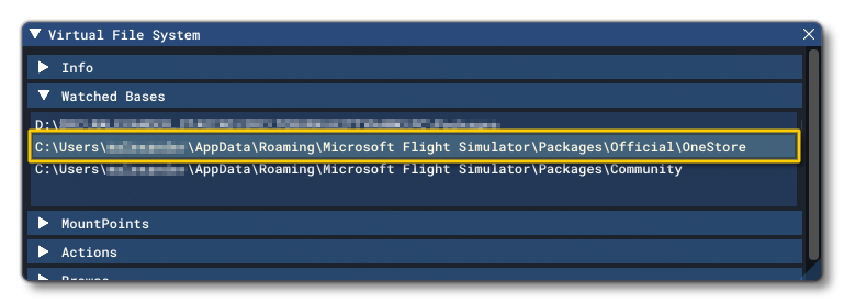
To find the OneStore root you can use The Virtual File System window:
Finally, model behaviors are also used to define Input Events. These are events that are triggered by some interaction between the user and an aircraft cockpit control, like a lever or a button. The input events are used to change or set a value corresponding to the control being used, using the SimVar associated with the control and RPN to modify the value. The XML contents for these events are described in full in the following section:
It is worth noting that the Input Events can also be used to intercept and override some of the general simulation key events, by binding Event IDs to an input event <Preset>. This is explained in the following section:
Basic Components
To get a better idea of how model behaviors are constructed let's look at a simple component within the context of the [model].xml file. In this file, components are added within the <Behaviors> element, and in the example below you can see a component for changing the visibility of something:
<?xml version="1.0" encoding="UTF-8"?>
<ModelInfo version="1.0" guid="<!-- GUID HERE -->">
<!-- General Model XML Here -->
    <Behaviors>
        <Component ID="Some_Unique_Id" Node="Node_Name_To_Hide_Here">
            <Visibility>
                <Parameter>
                    <Sim>
                        <Variable>STALL WARNING</Variable>
                        <Units>bool</Units>
                    </Sim>
                </Parameter>
            </Visibility>
        <Component>
    </Behaviors>
</ModelInfo>
In this example, you can see that the component is given an ID string and - in this case - a Node. The node comes from the model glTF and should be the name of a part in the 3D model. Within the component we tell the simulation what kind of behavior we are dealing with (visibility) and then define some parameters that will modify this behavior. In this case we're using a SimVar, which means that - in the simulation - the node for the model will be made visible/invisible depending on the value that the given SimVar has at any time.
NOTE: In this example the <Variable> and <Units> elements are required to define the SimVar, but there are also optional <Scale> and <Bias> elements for SimVars that can be included to.
This is the most basic way to add a component to the model XML and may even be the best approach when creating simple SimObjects other than aircraft. Note that the model behaviors XML is not just limited to using the <Component> element at it's top level, and it can also create <Macro> and <InputEvent> elements. You can find an explanation of these - and other - general template elements on the following page:
The documentation also has an interactive Template Explorer which can be accessed here:
<ModelBehaviors>
The <Behaviors> element is how all new SimObject behaviors should be defined, but previously this was done using the <ModelBehaviors> element, like this:
<ModelInfo version="1.0" guide="">
    <!-- Model Info XML here -->
</ModelInfo>
<ModelBehaviors>
    <!-- ModelBehaviors XML here -->
</ModelBehaviors>
This format has been deprecated for the [model].xml files and should not be used for new projects. However, everything described in this section of the documentation can be applied equally to <ModelBehaviors> as it can to <Behaviors>.
NOTE: <ModelBehaviors> is still a valid element when it is the root element for Input Events and Event templates.
Templates
More complex SimObjects will require more complex behaviors, and in an attempt to streamline things for developers and make creating model behaviors easier, Microsoft Flight Simulator makes use of a template system. This is basically a large quantity of components that have been pre-created and stored in various template files, and each of these components can be referenced from within any other component, or directly from the [model].xml file in the <Behaviors> element. The idea here is to reduce the time and effort required to create complex systems, since all you need to do is add in a template, and then override only those values that are relevant to the model the behavior is for.
NOTE: There is an interactive tool for exploring templates and model behaviours here: Template Explorer
Let's have a look at the visibility XML from before, but this time converted into a template:
<Template Name = "ASOBO_GT_Visibility_Sim">
    <Parameters type="Default">
        <VISIBILITY_SIMVAR_SCALE>1</VISIBILITY_SIMVAR_SCALE>
        <VISIBILITY_SIMVAR_BIAS>0</VISIBILITY_SIMVAR_BIAS>
    </Parameters>
    <Visibility>
        <Parameter>
            <Sim>
                <Variable>#VISIBILITY_SIMVAR#</Variable>
                <Units>#VISIBILITY_SIMVAR_UNITS#</Units>
                <Scale>#VISIBILITY_SIMVAR_SCALE#</Scale>
                <Bias>#VISIBILITY_SIMVAR_BIAS#</Bias>
            </Sim>
        </Parameter>
    </Visibility>
</Template>
In the XML above you can see that we have created a template with the name "ASOBO_GT_Visibility_Sim", and then we define some default values for the template. The default parameters are there to set values for any optional parameters that the user want's to omit if they use the template.
NOTE: The parameters of the XML will be processed in a linear order, from top to bottom.
We then define the actual <Visibility> element, and we supply the required SimVar parameters. You'll see that these are given names between hash # symbols. Using the # like that tells us that these values are the ones that the user will be able to set when they call the template, and they are also the names of the elements that the user will use to set the value. In this case - for example - we have "#VISIBILITY_SIMVAR#", which would become the <VISIBILITY_SIMVAR> element when the template is called.
IMPORTANT! Parameter elements created in this way can have some special attributes assigned to them. Please see the section below on Parameter Attributes for more information.
Now, to use the template above you'd have something like this in the [model].xml:
<?xml version="1.0" encoding="UTF-8"?>
<ModelInfo version="1.0" guid="<!-- GUID HERE -->">
<!-- General Model XML Here -->
    <Behaviors>
        <Include ModelBehaviorFile="Asobo\Generic\FX.xml"/>
        <Component ID="Some_Unique_Id" Node="Node_Name_To_Hide_Here">
            <UseTemplate Name="ASOBO_GT_Visibility_Sim">
                <VISIBILITY_SIMVAR>STALL WARNING</VISIBILITY_SIMVAR>
                <VISIBILITY_SIMVAR_UNITS>bool</VISIBILITY_SIMVAR_UNITS>
            </UseTemplate>
        </Component>
    </Behaviors>
</ModelInfo>
The important thing to note here is the <Include /> element, which specifies the model behavior XML file that has the template(s) that we want to reference. This is required when using the template system to tell Microsoft Flight Simulator where to look to find the template that is being used, and it should be called at start of the XML defining the <Behaviors>.
It's worth mentioning too that you can use the element # naming system to create values using multiple inputs. For example, consider the following template element:
<WWISE_EVENT_1>#LIGHT_TYPE#_light_#INTERACTION_TYPE#_on</WWISE_EVENT_1>Here you have two "custom" values that would be generated from the XML that uses the template like this:
<LIGHT_TYPE>landing</LIGHT_TYPE>
<INTERACTION_TYPE>switch</INTERACTION_TYPE>
So, this essentially creates the value "landing_light_switch_on", which is passed to the Wwise event in this case.
Finally, here's the same visibility template, only this time set up to use RPN rather than a SimVar to determine the outcome:
<Template Name = "ASOBO_GT_Visibility_Code">
    <Parameter type="Default">
        <ONCE>False</ONCE>
    </Parameter>
    <Visibility Once="#ONCE#">
        <Parameter>
            <Code>#VISIBILITY_CODE#</Code>
        </Parameter>
    </Visibility>
</Template>
We'll be referencing both the SimVar and RPN versions of this template in the XML Programs section.
Parameter Attributes
When creating custom XML parameter elements using the # symbol (as explained in the section on Templates), there is a special pre-defined attribute that can be used when calling the element elsewhere in the XML:
| Attribute | Description | Type | Required |
|---|---|---|---|
Process |
This processes the contents of the parameter ins a specific way, as explained below. |
String:
|
No |
The attribute types listed above will do the following:
- Int: Compute the contents of the element using RPN, with an integer result.
- Float: Compute the contents of the element using RPN, with an float result.
- Param: Get the content of a parameter by name when it is not possible to use
#PARAM_NAME#. What this means is that the#parameter will first be evaluated, then it's value will be used to create the parameter within the node (see the example below). - String: Allow a parameter to be processed as a string using the RPN String Operators.
Here are some examples of use:
<SIMVAR_INDEX Process="Param">#TYPE##ID#_SIMVAR_INDEX</SIMVAR_INDEX>
<MIN_SPEED_TAKEOFF_LIFT Process="Float">#MIN_SPEED_TAKEOFF_HYDRAULICS# 0.45 *</MIN_SPEED_TAKEOFF_LIFT>
<STATE_ON_ID Process="Int">#DIMMER_POS_0_VALUE# 100 == if{ 0 quit } #DIMMER_POS_1_VALUE# 100 == if{ 1 quit } 2</STATE_ON_ID>
<PREFIXED_ID Process="String">#ID# '%03d' @sprintf</PREFIXED_ID>
XML Programs
One important feature of using the template system is that you can create "XML Programs" that use different XML elements to create small programs that will change the model behavior based on the outcome of some calculation or check. Generally you'll find these XML programs in the lowest level of the template hierarchy, in the "sub-templates", however they can be used just about anywhere.
To give an example of how these elements can be used, we'll build on the visibility template examples given in the sections above, and use them to create our own template. In this template we'll do a conditional check to use either a SimVar or some RPN code to decide if the model node should be visible or not:
<Template Name="MyVisibilityTemplate">
    <Component ID="#NODE_ID#" Node="#NODE_ID#">
        <Condition NotEmpty="VISIBILITY_CODE">
            <True>
                <UseTemplate Name="ASOBO_GT_Visibility_Code"/>
            </True>
            <False>
                <UseTemplate Name="ASOBO_GT_Visibility_Sim"/>
            </False>
        </Condition>
    </Component>
</Template>
This custom template is using a conditional check to see if the element <VISIBILITY_CODE> is "empty" or not.
NOTE: An "empty" node is a node that has been created but has no assigned value, while a node that does not exist would be considered as "undefined" rather than "empty".If it is not empty - the condition is True - then the ASOBO_GT_Visibility_Code template will be used, and if it is empty - the condition is false - then ASOBO_GT_Visibility_Sim will be used. Where does the <VISIBILITY_CODE> element come from? Well, that would be from some XML that is either in another template, or in the [model].xml itself, and it would look like this when using RPN:
<UseTemplate Name="MyVisibilityTemplate">
    <NODE_ID>NodeNameToHide</NODE_ID>
    <VISIBILITY_CODE>(A:STALL WARNING, Bool)</VISIBILITY_CODE>
</UseTemplate>
Or it would look like this when using a SimVar:
<UseTemplate Name="MyVisibilityTemplate">
    <NODE_ID>NodeNameToHide</NODE_ID>
    <VISIBILITY_SIMVAR>STALL WARNING</VISIBILITY_SIMVAR>
    <VISIBILITY_SIMVAR_UNITS>Bool</VISIBILITY_SIMVAR_UNITS>
</UseTemplate>
So, either one of the XML snippets above will call the template "MyVisibilityTemplate", and if you use the one with the <VISIBILITY_CODE> element, then the conditional check will use the supplied RPN code to set the visibility, while if you use the other one, then a SimVar will be used. This is a very simple example of how a simple XML program is created, but there are a great number of program XML elements that can be used to modify the way any template resolves based on the given inputs.
You can find out more about all the specific programming elements from the following page:
And you can find examples of the main "building block" elements for these programs on this page:
Input Parameters
When dealing with Input Events, some initial value is normally passed in from the input source, which is usually a <MouseRect>. This will contain some RPN code that generates the initial value for the button, lever, switch, etc... that is being interacted with. This value is then passed through to the <InputEvent> as the variable pN, where N is a value starting at 0 and incrementing for each parameter that is being passed into the input event.
To give an example, we'll imagine a simple button that is used to set the COM volume to 50% . In this case our <MouseRect> will have this snippet of RPN:
50 (>B:SOUND_COM_1_Volume_Set)
This is calling the InputEvent "SOUND_COM_1_Volume", and is using the code defined in the <Set> element to generate the actual event. This element would look like this:
<Set>
<Code>p0 0 max 100 min (>O:MyValue) (O:MyValue) (>K:COM1_VOLUME_SET)</Code>
<Parameters>
<Param Type="Float" RPN="True">p0</Param>
</Parameters>
</Set>
Here, all that's happening is that the value contained in p0 is being passed into the input parameter without being modified, then it is being output and becomes the p0 input used in the <Code> element, where the RPN uses it to set the "MyValue" component variable. This will then be used to set the COM VOLUME SimVar, as defined in the <Value> element of the XML:
<Value>
<Units>percent</Units>
<Code>(O:MyValue)</Code>
<Init>(A:COM VOLUME:1, percent) (>O:MyValue)</Init>
<WatchVars>
<Simvar ID="COM VOLUME:1"/>
</WatchVars>
</Value>IMPORTANT! Even if you do not wish to modify the p0 input, you must declare it as a <Param>, as shown in the <Set> example, above. Trying to access p0 without first having assigned a parameter will cause errors.
Another important thing to note is how the input parameters are affected by the use of RPN or not, since a <Param> that is not using RPN will not be considered as using an input parameter at all. For example, consider this XML that has various bindings with 2 parameters in each:
<Set>
<Code>p0 if{ (>H:My_Event_True) } els{ (>H:My_Event_False) } p1 (>O:MyValue)</Code>
<Parameters>
<Param Type="Float" RPN="True">p0</Param>
<Param Type="Float" RPN="True">p1</Param>
</Parameters>
<Bindings>
<Binding Alias="EVENT_Set_Value_True">
<Param>1</Param>
<Param RPN="True">p0</Param>
</Binding>
<Binding Alias="EVENT_Set_Value_False">
<Param>0</Param>
<Param RPN="True">p0</Param>
</Binding>
<Binding Alias="EVENT_Set_Value_Toggle">
<Param RPN="True">(L:MY_VALUE_IS_ON) !</Param>
<Param RPN="True">p0</Param>
</Binding>
</Bindings>
</Set>
If you look at the alias "EVENT_Set_Value_True", here we only have one input parameter, which is p0, but we will be outputting two parameters: 1 and p0 (in that order since the XML is parsed in a linear form). This means that in the "set" <Code>, the first input parameter - p0 - is 1 and the second input parameter - p1 - is the initial input value from p0. To make it clearer, let's label the inputs and outputs:
<Binding Alias="EVENT_Set_Value_True">
<!-- No Input -->   <Param>1</Param>               <!-- p0 Output -->
<!-- p0 Input -->   <Param RPN="True">p0</Param>   <!-- p1 Output -->
</Binding>
Essentially you can consider the pN format as simply defining a local scope variable to hold a value until the next operation.
You can find a full example that illustrates input parameters as well as the creation of a simple input event from the following section:
You can also find more information on input bindings from the section below, and we have a full tutorial on using the vairous templates and parameters for simple interactions here:
Input Bindings
An important feature of Input Events is that they can be bound to Event IDs or even to each other. This means that you can use an Input Event to override a default key event behavior using your own code, or you can create aliases for different presets within your own behaviors. Let's consider the following example for setting a value inside the input event <Preset> "Sound_COM1_Volume":
<Set>
<Code>p0 0 max 100 min s0 (>O:MyValue) l0 (>K:COM1_VOLUME_SET)</Code>
<Parameters>
<Param Type="Float" RPN="True">p0 100 *</Param>
</Parameters>
<Bindings>
<Binding EventID="COM1_VOLUME_SET">
<Param RPN="True">p0 16384 /</Param>
<!-- convert -16k/16k value to -1/1 value -->
</Binding>
<Binding Alias="SOUND_COM_1_Volume_Min">
<Param>0</Param>
</Binding>
<Binding Alias="SOUND_COM_1_Volume_Max">
<Param>1</Param>
</Binding>
</Bindings>
</Set>In this example, a binding that overrides the behavior of an Event ID has been defined with the attribute "EventID":
<Binding EventID="COM1_VOLUME_SET">This will now intercept the simulation event KEY_COM1_VOLUME_SET and instead use the <Code> within the <Set> element. Note that when setting the binding to an event ID, the Input Parameter p0 will usually be the raw input value - which would be between -16383 and 16384 for axis input and between 0 and 1 for a single input. The parameter p1 will also always have data, and in most cases this will be the same as the p0 data, however it may also have been pre-processed in some way before being pushed to the input event. The parameters p2 - p6 may also contain data, depending on the KEY_ event being checked.
NOTE: If you plan on using KEY_ events in checklists, and those events are intercepted by an input event preset, then you have to use the p1 value and above, as p0 will always return 0 when a checklist has generated the event.
In the above example we also generate a couple of aliases that can be used to override the Input Parameters, in this case outputting a value of 0 or 1 and ignoring the p0 input:
<Binding Alias="SOUND_COM_1_Volume_Min">
<Binding Alias="SOUND_COM_1_Volume_Max">
When creating an alias, it can be whatever you want as long as it is unique, but to avoid naming conflicts we advise that you always use the base Input Event preset name suffixed by a custom name describing what the alias does. For example, to set the COM1 volume to the minimum we created the alias "SOUND_COM_1_Volume_Min" for the preset "SOUND_COM_1_Volume", which means that in RPN calling:
(>B:SOUND_COM_1_Volume_Min)would do the same thing as:
0 (>B:SOUND_COM_1_Volume_Set)
Parameter Functions
Much like Templates, parameter functions are a form of creating reusable XML that can be applied in multiple different circumstances without having to repeatedly type out the same elements. The concept here is that you can use XML Programing elements to create custom functions that can then be used within the different areas of the behaviors files. These functions are created using the <ParametersFn> element, which would be done within the <Behaviors> element (or within the <ModelBehaviors> element, if you want to create library files of functions). Once defined, the function can be called using the <UseParametersFn> element within a template or a component. Below you can see a simple schematic showing how all this comes together:
<?xml version="1.0" encoding="UTF-8"?>
<ModelInfo version="1.0" guid="<!-- GUID HERE -->">
<!-- General Model XML Here -->
    <Behaviors>
        <ParametersFn ID="GET_NODE_ID_AND_ANIM_NAME_FOR_BASE_NAME">
            <ReturnParameters>
                <NODE_ID>#BASE_NAME#</NODE_ID>
                <ANIM_NAME>#BASE_NAME#</ANIM_NAME>
            </ReturnParameters>
        </ParametersFn>
        <Component ID="EXAMPLE">
            <Parameters Type="Override">
                <UseParametersFn Name="GET_NODE_ID_AND_ANIM_NAME_FOR_BASE_NAME">
                    <BASE_NAME>A_NAME</BASE_NAME>
                </UseParametersFn>
                <!-- will load: -->
                <!-- <NODE_ID>A_NAME</NODE_ID> -->
                <!-- <ANIM_NAME>A_NAME</ANIM_NAME> -->
            </Parameters>
            <Component ID="EXAMPLE_COMPONENT" Node="#NODE_ID#"><!-- make use of the NODE_ID here -->
                <!-- do other stuff .. -->
            </Component>
        </Component>
    </Behaviors>
</ModelInfo>
In this example we have a function that will return two parameters (NODE_ID and ANIM_NAME) that have been set to hold the <BASE_NAME> string. We then have a component that calls the function before using the parameters that it generates. This is the simplest and most straightforward way to use this functionality, but it's worth noting that within a parameter function you can use XML Programing to create more complex procedures for generating parameters, and you can also nest functions, eg: your function can perform some operation and then in the <ReturnParameters> call another function to perform further operations on the parameters. The snippet below illustrates this:
<ParametersFn Name="ASOBO_FN_Get_Interaction_Parameters_Positions_OnAutoOff">
    <Parameters Type="Default">
        <POS_ON>0</POS_ON>
        <POS_AUTO>1</POS_AUTO>
        <POS_OFF>2</POS_OFF>
        <POS_ON_NAME>On</POS_ON_NAME>
        <POS_AUTO_NAME>Auto</POS_AUTO_NAME>
        <POS_OFF_NAME>Off</POS_OFF_NAME>
    </Parameters>
    <ReturnParameters>
        <UseParametersFn Name="ASOBO_FN_Get_Interaction_Parameters_X_Positions">
            <POS_ID_#POS_ON#>#POS_ON_NAME#</POS_ID_#POS_ON#>
            <POS_ID_#POS_AUTO#>#POS_AUTO_NAME#</POS_ID_#POS_AUTO#>
            <POS_ID_#POS_OFF#>#POS_OFF_NAME#</POS_ID_#POS_OFF#>
        </UseParametersFn>
    </ReturnParameters>
</ParametersFn>
You can find further examples for parameter functions on the following page: