DEBUG AIRCRAFT CFD
 This option will open the CFD (Computational Fluid Dynamics) Debug window shown above, with the CFD Simulation Running option checked. When enabled, the flow of air around the aircraft is computationally simulated so that you can use it to better understand - and improve - the aerodynamics and handling of the aircraft.
IMPORTANT! This is a new feature that has been made public so that you can test it and compare results. Feedback, issues and errors related to this feature can be posted on the Official Dev Support Forum.
How It Works
The CFD currently proposed uses a default of 20 x 20 x 20 cubic voxels that englobe the aircraft. When enabled, the simulation will then solve a custom version of the Navier Stokes equations that includes upwind advection solving designed to cope with high fluid velocities. The CFD is solved over each of the voxels by the CPU at a rate of 100 times per second with three global passes per iteration. The load is spread over 5 different threads for minimal cpu impact.
It should be noted that while the formulas used in this simulation are well known and proven, the implementation in Microsoft Flight Simulator is still experimental. Also note that while we display the absolute speed, pressure, and temperature values, as well as the deviation measurements, this data may not be exact and may require improvement over coming iterations of the debug window. Finally, it is important to understand that enabling the CFD simulation may introduce behaviors that can break the flight model. For example, with the CFD simulation enabled, the airflow generated by the aircraft propeller will hit the fuselage and change the propeller effects such as the p-factor.
Options
When you check the CFD Simulation Running option, the window will show additional information and optional checkboxes (note that if the aircraft flight model CFG file has the CFD_EnableSimulation parameter set to 1 (TRUE) then this option will already be checked and cannot be unchecked). Checking this option allocates the memory and runs the Navier Stokes fluid simulation over the discretised space around the aircraft. The rest of the options are explained below:
NOTE: You should only use these options individually, and activating more than one - or all of them - will not display correct information.
-
Air Flow Visualisation
Checking this will enable the airflow visualisation, which displays the air speed vector field as static lines. Air speed is measured relative to a fixed point on the aircraft. In this mode, the air is moving fast relative to the flying aircraft, and passing by the aircraft at an average of the airspeed in ktas of the aircraft.
-
Air Flow (World Space) Visualisation
Checking this will enable the airflow visualisation, which displays the air speed vector field as static lines. Air speed is measured relative to a fixed point on the world. In this mode, the air around the aircraft is barely moving (or moving only with the wind) relative to the world. When passing through that air, the aircraft pushes some of the air down which pushes the aircraft up (Newton's 3rd law), and some air is pushed forward and pushes the aircraft backwards, which - in turn - creates lift. However the air will still move slowly compared to the aircraft's speed.
-
Particle Flow Visualisation
Checking this will enable the particle visualisation where you can see the airflow as individual moving particles. Air speed is measured relative to a fixed point on the aircraft. In this mode, the air is moving fast relative to the flying aircraft, and passing by the aircraft at an average of the airspeed in ktas of the aircraft.
-
Particle Flow (World Space) Visualisation
Checking this will enable the particle visualisation where you can see the airflow as individual moving particles. Air speed is measured relative to a fixed point on the world. In this mode, the air around the aircraft is barely moving (or moving only with the wind) relative to the world. When passing through that air, the aircraft pushes some of the air down which pushes the aircraft up (Newton's 3rd law), and some air is pushed forward and pushes the aircraft backwards, which - in turn - creates lift. However the air will still move slowly compared to the aircraft's speed.

-
Particle CFD Visualisation
When this is enabled, the airflow will be simulated using some simple particles, removing the colour gradients and heavy lines, making its visualisation a bit more holistic:

-
Voxel CFD Visualisation
When this is enabled, each voxel in the CFD that is affecting the simulation will be shown within the voxel space:

-
Reinject Data Into Flight Model
When checked, this option will affect the interaction (collision calculation) between the fluid simulation and the rigid body aircraft simulation (note that if the aircraftflight model CFGfile has theCFD_ReinjectBodyparameter set to 1 (TRUE) then this option will already be checked and cannot be unchecked). In theory the force applied on the fluid by the airframe is always exactly opposite from the force applied on the airframe by the fluid.- When the option is unchecked: In this mode - when the interaction between fluid and rigid body is calculated - the fluid will receive the exact body to fluid force. However, the body will not receive the exact opposite force. The force received by the body will be overwritten by the aerodynamic forces as computed by the previously existing, non-CFD, calculations (which are run in parallel). What this means is that the CFD simulation is aware of the aircraft, but the aircraft will be processed by the non-CFD aerodynamic simulation and ignore the CFD simulation. Note that in this mode, Newton's third law is not respected, and the simulation will run as if there was no CFD calculated, and the CFD can be visualized but has no effect on the airframe.
- When the option is checked: In this mode the aircraft body will receive the exact opposite force to that which the fluid receives, and Newton's third law is respected. The aircraft will be flying fully on the results of the CFD simulation, and the results of the previously existing non-CFD airflow simulation are discarded. This will also supply you with further options that can enable/disable reinjection for some specific surfaces in order to make the port to the CFD system easier and to help eliminate bugs and problems:
- Rotors: When enabled, the airflow is reinjected for rotors and the air passing by the rotor will no longer move at the airspeed of the aircraft, but at the airspeed accelerated by the rotor. This is more realistic but will affect the performance of the rotors and may require an update of the rotor parameters. Note that this option requires that the propellers have been setup to use the new surface based propeller mode (see
prop_mod_use_modernfor more details). - VTailX and HTailY: When enabled the CFD calculation forces are reinjected for the X and Y components that are applied on the tail control surfaces of the airframe. This option exists because the airflow simulated by the CFD is significantly affected and will be different from the average airflow around the airplane. Enabling this will require a complete trim and tail control surface effectiveness re-tune, but the result is a much more realistic simulation of deep stall and propeller wash.
- Rotors: When enabled, the airflow is reinjected for rotors and the air passing by the rotor will no longer move at the airspeed of the aircraft, but at the airspeed accelerated by the rotor. This is more realistic but will affect the performance of the rotors and may require an update of the rotor parameters. Note that this option requires that the propellers have been setup to use the new surface based propeller mode (see
-
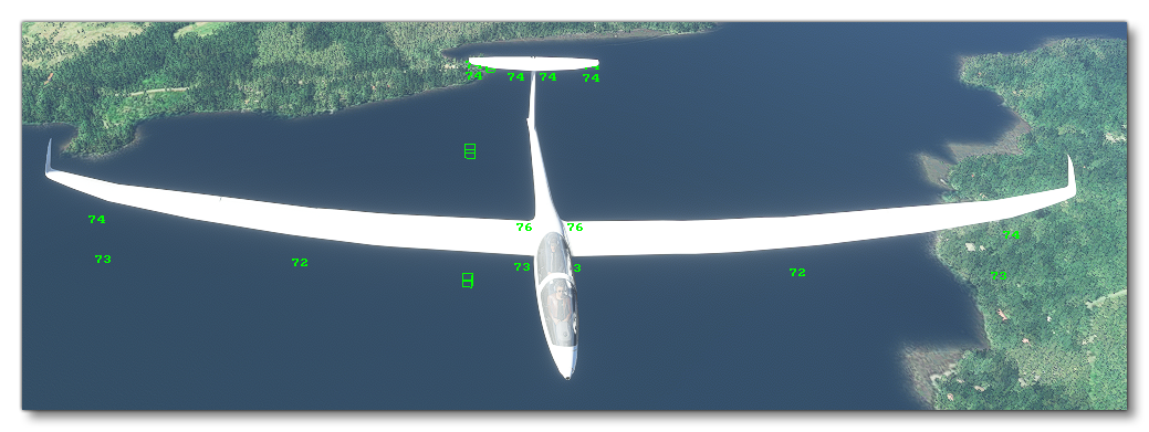
Show CFD Measure Points
This option will show the prop-wash measure points of the aircraft and the values they are registering when using the CFD simulation, and can be used to debug the flight model by comparing them to the values of the real aircraft:
How To Use
The following list gives the recommended instructions for general usage of the CFD debug window:
- Before using the window, if you are debugging a propeller aircraft, you should ensure that you are using the modern propellor model. See here for more information:
prop_mod_use_modern. - Enable the CFD simulation, but ensure the flight model reinjection option is unchecked.
- Check the airflow field lines in all 4 visualization modes and verify that everything seems correct. Use the debug values at the various points of the aircraft and check the airflow readings and verify that everything is correct.
- If the simulation looks like it is not working, or has issues, then use the viscosity, incompressibilty, voxel size, and voxel number variables to tweak the CFD for better results (see the
CFD_AirViscosityand subsequent parameters for more information). - Once it appears that the CFD simulation is working as it should, enable the flight model reinjection. However, ensure that the the Rotor, VtailX and HtailY reinjection options are unchecked.
- Check the general aircraft behaviour and the airflow field lines in all conditions and aircraft configurations, applying corrections to the aircraft parameters where necessary.
- Once you have tested with the CFD (and flight model injection) enabled, and you have tweaked your aircraft parameters to give the most accurate possible flying experience, you can then go ahead and enable the CFD simulation to be used for the aircraft permanently using the CFD parameters listed in the
flight_model.cfg(for example:CFD_EnableSimulation).
When the flight model reinjection has been enabled, the following aircraft details will probably be affected and should be monitored:
- Engine Wash / P-factor: With the CFD being reinjected, prop wash will be fully simulated. Prop wash will hit the wings, fuselage sometimes at a very high speed and with a lot of energy. The prop wash will often have a different orientation than front-back. It can completely change engine effects, amplify or cancel out p-factor, generate exaggerated control surface effectiveness.
- Tail Control Surface Effectiveness: The air that hits the tail may will be deflected by the surfaces in front of the tail (propeller, wing, fuselage). This will impact trim, effectiveness, range of controls.
- Self Impact: When the reinjection is ON, the air pushes the surface which pushes the air which pushes the surface... In some occasions this may create unwanted "flutter" and oscillations. A debug of AP oscillations, control surface oscillations, resonance, and flutter, may be necessary in these cases.