MODEL BEHAVIOURS
This section explains how to use the Model Behavior system and the Input Events to connect the nodes and animations that have been created by artists so that the plane reacts correctly to the various user inputs. This is done by building XML files that describe the different properties of each instrument. Using this system enables you to create templates that can be used to reduce greatly the amount of duplicated code and build up a library of functions that can be reused as you build more planes.
Before continuing, it is worth noting that using and creating Model Behaviors is a big task and requires a certain amount of work. As such, we strongly suggest that you revise the following pages of the main documentation to get a greater understanding of the information given in this section:
Setup
In the section on the Model CFG and Aircraft XML, you should have created some XML files that are meant to contain the Model Behavior code. In most cases, you will have created one file for the interior of the plane and one for the exterior. Their names should correspond to the names that are defined inside of the model.cfg file next to the parameters interior (for the interior) and normal (for the exterior).
While the standard structure would be to have both XML files inside of the model folder along with the model.cfg file, it is possible for them to be located elsewhere. This can be useful for variations, where the variation has exactly the same nodes and animations and doesn't require it's own XML file. Basically this lets you use the base aircraft XML file rather than having to write a custom one each time.
NOTE: The XML files that you have created can be opened with any text editor, though text editors that are designed for coding such as Notepad++ or Visual Studio are advised.
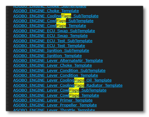
It is very important to note that there have been a great number of model behavior templates created for the default aircraft available in Microsoft Flight Simulator. These tmeplates can be used for your own aircraft, and we strongly recommend that whenever you want to implement an instrument or behavior, it is advised to search through the templates folder for anything that may be appropriate. This task is made simpler by using the SDK documentation, where all the templates are listed and can be explored:
As an Example, if you go to that page and then search "Flaps", you will see highlighted a number of templates that can be of use to you, and these can be used to easily implement flaps behavior without having to reinvent the wheel:
File Structure
The model XML files are standard XML files which should contain a single <ModelInfo> tag at their root. That tag will contain a <LODS> tag that is used by the artists to setup when LODs should change (this should already have been filled in), and a <Behaviors> tag which will contain all the model behavior implementation.
NOTE: Some older aircraft may have the <ModelBehaviors> tag in their XML files. This is a deprecated way to structure the file, and you should be using the <Behaviors> tag that is described above.
Once you have setup these initial tags, you can then move on and add in the <Include> tags, inside of the <Behaviors> tags. This will be used to include the files containing the XML Templates that you are planning to use. If at any point you decide you need to use a template from a new file, then a new <Include> will need to be added.
If you are expecting to create a number of templates specific to the aircaft you are working on, it can be a good idea to create one or more extra XML files to store those templates, and these will also be included in the model XML.
Once you've added the files to be included, you should add the <IncludeBase> tags, if required. This is used when an aircraft is a variation of another aircraft and allows you to include all the XML from that aircraft. For example, using it on a ski variation of an aircraft allows you to only have to define the ski specific components rather than having to duplicate the whole XML file. On an aircraft which is not using another aircraft as a base, this tag should not be used.
Finally, to complete the initial setup, you should also have one or more <Component> tags. These will be used to separate the different sections of the aircraft, and - since they can be imbricated - you can use them to describe broad sections, and then define panels, and then define individual instruments or switches. Here is an example of the overall basic structure:
<Behaviors>
    <Component ID="Left_Panel">
        <Component ID="Throttle_Section">
        </Component>
        <Component ID="Lights_Section">
            <Component ID="Exterior_Lights">
            </Component>
            <Component ID="Interior_Lights">
            </Component>
        </Component>
    </Component>
    <Component ID="Right_Panel">
        <Component ID="Fuel_Section">
        </Component>
        <Component ID="Trim_Section">
        </Component>
    </Component>
    <Component ID="Front_Panel">
        <Component ID="Instruments_Section">
        </Component>
        <Component ID="Glasscockpits_Section">
        </Component>
    </Component>
    <Component ID="Overhead_Panel">
         <Component ID="Engine_Start_Section">
         </Component>
    </Component>
</Behaviors>
Writing a clear and logical structure can be very important in making sure that the XML code is maintainable and that debugging is simpler. It is worth taking the extra time to setup and prepare things properly before diving into implementing the different interactions.
Components Hierarchy
A Behavior is defined using <Component> nodes, and a hierarchy of these nodes can be defined. In general, when defining a component hierarchy, you'll be using the following elements:
<CameraTitle><FX><AnimationTriggers><Visibility><EmissiveFactor><Update><Animation><MouseRect><UseInputEvent>
These elements are the main content you'll want to create, since they can take care of animation, interactions, visual FXs, Emissives and so on. Everything that has to be dynamic can be defined using a concrete component.
Each component is has to be given an "ID" and optionally a "Node" which will correspond to a node in the 3D model. For some elements such as <MouseRect> or <EmissiveFactor>, these can only be defined inside components with a Node. This node will be the one used to generate the clickable area in the case of a <MouseRect> and the emissive mesh for an <EmissiveFactor>. Generally, components will be structured as so:
<Component ID="A_Component">
    <!-- Elements definition here -->
    <!-- Only elements that don't require a node as target -->
    <!-- list: Animation, Triggers, Update, FX, InputEvent -->
</Component>
<Component ID="An_Other_Component" Node="A_GLTF_Node">
    <!-- Elements definition here -->
    <!-- Any element can be created here as there is a node defined -->
</Component>
Syntax
A component can be defined within a template definition or within a <Behaviors> or a <ModelBehaviours> node. A component "ID" must be unique within the same scope.
<Component ID="Invalid_Declaration">
    <Component ID="A_Component"/>
    <Component ID="A_Component"/><!-- "A_Component" already exists! -->
</Component>
<Component ID="Valid_Declaration">
    <Component ID="A_Component"/>
    <Component ID="B_Component"/>
</Component>
Override
A component UID is defined by it's place in the hierarchy.
<!-- in some behavior file some_behavior.xml -->
<Component ID="Root_Component">
    <Component ID="Child_Comp"/><!-- UID is Root_Component:Child_Comp -->
</Component>
The component content can be overridden when it is included using <IncludeBase>. You would redefine the component content to target a specific component using its UID with the attribute "OverrideID".
<!-- in an other behavior file -->
<IncludeBase RelativeFile="some_behavior.xml"/>
    <!-- Any content defined originally by the component in some_behavior.xml -->
    <!-- will be replaced by this definition instead -->
<Component ID="A_Component" OverrideID="Root_Component:Child_Comp"/>
Parameters
Components essentially push a scope on the stack of parameters, and parameters defined within a component will be valid for the whole parsing of the elements defined in the same scope or below. Here we're going to concentrate on one important feature of the parameter system which is being able to save and load parameters as part of a component, since the sections on <Parameters> and Model Behaviors already have extensive information about what parameters are and how to use them correctly.
Save parameters
A parameters save <SaveParameters> can be defined anywhere a <Parameters> can be defined. The save is given a unique identifier value and a list of parameters to save. For example:
<SaveParameters ID="Save_ID">
    <A_PARAM>A Value</A_PARAM>
</SaveParameters>
This way of saving parameters is destructive, meaning that - unless an Append rule is defined - the save will be reset if it already existed, and only the new parameters being set for saving will be stored:
<SaveParameters ID="An_Other_Save_ID">
    <A_PARAM>A Value</A_PARAM>
</SaveParameters>
<SaveParameters ID="An_Other_Save_ID">
    <ANOTHER_PARAM>An other Value</ANOTHER_PARAM>
</SaveParameters>
<!-- /!\\ warning A_PARAM has been deleted -->
<!-- the saved parameters with ID Another_Save_ID has a parameter -->
<!-- ANOTHER_PARAM with value "An other Value" -->
Using an Append rule will prevent this behavior and give you some control over how any exisiting parameter value should be handled:
<SaveParameters ID="Save_ID">
    <A_PARAM>A Value</A_PARAM>
</SaveParameters>
<SaveParameters ID="Save_ID" Append="Override">
    <ANOTHER_VALUE>B Value</ANOTHER_VALUE>
</SaveParameters>
<SaveParameters ID="Save_ID" Append="Default">
    <A_PARAM>Override attempt</A_PARAM>
</SaveParameters>
<!-- the saved parameters with ID Save_ID has a parameter -->
<!-- A_PARAM with value "A Value" -->
<!-- ANOTHER_VALUE with value "B Value" -->
Load parameters
The element <LoadParameters /> can be used to load a copy of the contents of a previous save onto the current parameters stack. Note that performing a load operation is not destructive, and loaded parameters will still exist in the save with the same value. Essentially, the action is always to load a copy.
<SaveParameters ID="Save_ID">
    <A_PARAM>A Value</A_PARAM>
</SaveParameters>
<LoadParameters ID="Save_ID"/>
<!-- Stack now has a parameter A_PARAM with a value "A Value" -->
<!-- Save_ID still exists -->
Note that if a save isn't found for the given ID then the load will simply fail silently. The existence of a saved parameter file can be checked using the <Condition> attribute CheckSavedParameters where the attribute value is the ID of the save to look up.
Remove saved parameters
The element <RemoveSavedParameters /> can be used to remove a saved stack of parameters.
<SaveParameters ID="Save_ID">
	<A_PARAM>A Value</A_PARAM>
</SaveParameters>
<LoadParameters ID="Save_ID"/>
<RemoveSavedParameters ID="Save_ID"/>
<!-- Stack now has a parameter A_PARAM with a value "A Value" -->
<!-- Save_ID doesnt exist anymore -->
Similarly to <LoadParameters />, if a save isn't found for the given ID, the removal will fail silently.
Using Input Events
As part of the Model Behaviors, you can use Input Events. While this is a complex system to use, and interactions can be implemented without them, it is recommended to use this system and add an Input Event for each interaction. This is because they provide the following powerful features:
- Input Events allow you to create Increase/Decrease operations for your interaction, which enables gamepad interactions, using the lock/unlock system.
- Input Events allow you to intercept key Event IDs in order to force them to go through the Input Event's code rather than the normal C++ code.
NOTE: This also means that you can disable some key events, or add some XML code to keys (By intercepting them, running your XML code, then calling that Key again
- Input Events allow you to abstract a number of events into a single shorthand. As an example, to make the Copilot press a button in the checklist, you would normally have to set both the variable (and/or possible key) driving the button itself, but also for momentary buttons an extra LocalVar to make the button stay down for a second. Using input events, you can create a shorthand which holds down the button for a limited time, which can then be called Checklist side in a single instruction.
You can find a full and detailed tutorial on input events within the SDK documentation:
Conventions
There are a number of conventions that the Model Behavior templates use which you should be aware of. Unless you are writing your templates by hand, you will want to have your artists follow these conventions to ensure that the templates behave properly:
- When an interaction (switch/lever/etc...) has a normal On/Off logic, frame 0 of the animation should correspond to Off, and the maximum frame should correspond to On.
- When a knob can do a full 360° rotation, it should have at least 3, equidistant, frames in its animation to ensure that it rotates in the right direction.
- When a knob can do a full 360° rotation, it should have its first and last frame at the same position, and the XML should set the
<WRAP>parameter to true to ensure it properly wraps from 360° to 0°.
- When a switch has more than 2 positions, it should have frame 0 at the top position - for vertical switches - or the left position - for horizontal switches.
- Whenever possible, animations should have the same name as the nodes they are animating.
- Enabling the
<USE_TRAJECTORY_DRAG_MODE>parameter for a lever can allow you to have a dragging interaction where that lever's position is based on the animation position. It generally results in a more natural interaction, but it requires that the lever's animation frame 0 is at its minimum position, and its final frame is at its maximum position.
- Animations should be linear to be accurate, especially for needles.
- When the gauge of a needle does not have linear intervals (say if an RPM gauge has the same angle between 0° and 40° than between 40° and 60°), the artist can separate the animation in linear intervals, to facilitate its XML implementation. If that artists adds frames at 0, 20, 40 and 60, the default needle template will be able to properly animate the needle without having to account for the non-linear gauge.