THE MODELLING PROCESS
This page gives some general guidelines related to modelling the cockpit for the aircraft. It is worth reading the page for the airframe before continuing, as the guidelines given their are generally also applicable to modelling the cockpit:
Cockpit Poly Count
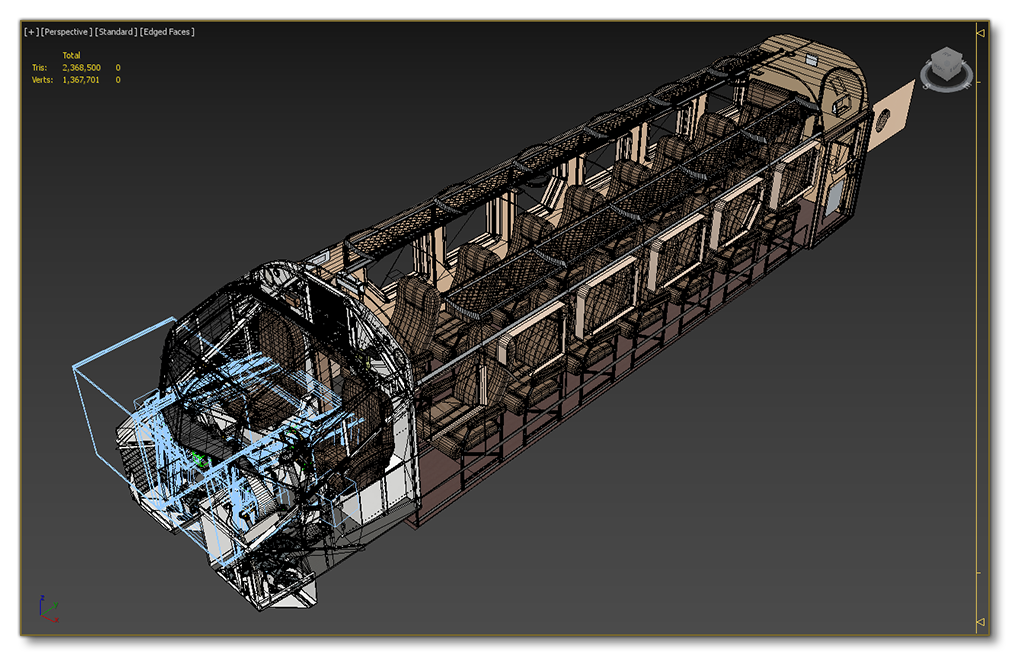
Before starting with the aircraft cockpit, it's good to be aware of the limitations of the simulation and the recommended polygon count for the aircraft that you are making. Aircraft that go over the recommended limits will be considered un-optimized and may cause issues when used in the simulation, so we strongly recommend that you pay attention to these values when creating your models.
The table below is a general guide as to how many triangles you can spend on a single plane asset:
| Plane Size | Plane Description | Triangle Count Interior |
|---|---|---|
| Extra Large plane | Jumbo Jet | 500,000 tris |
| Large plane | Large Passenger Jet | 400,000 tris |
| Medium plane | Small Passenger Jet | 200,000 tris |
| Small plane | Single/Double Seater | 150,000 tris |
Since this part of the documentation deals with creating the cockpit model with the highest possible fidelity for LOD0, the above table doesn't show the polgon count for the other LODs. However, you can find all the information on the optimal number of polygons to use for each LOD level on the following page:
Match Mesh With Airframe
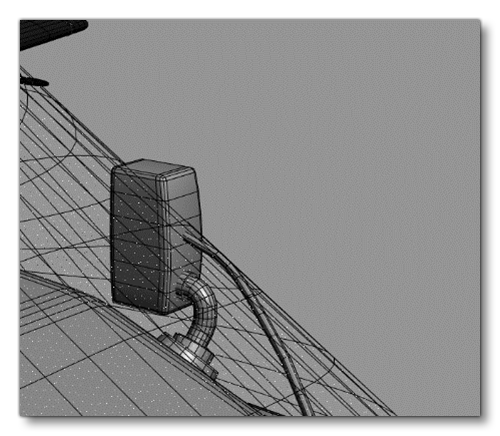
When you create a cockpit (and/or a cabin) you must check that your mesh will fit inside the airframe, so you will need to test by merging the cockpit into the airframe file temporarily. Once you have done the import, you will need to verify that all the joints are good and that there are no holes between the cockpit and the airframe. No mesh from the cockpit should be visible outside of the aircraft, for example, the image below shows a cockpit which does not adequately match the airframe - a component is going through the windshield:
Ultra High-Res Geometry
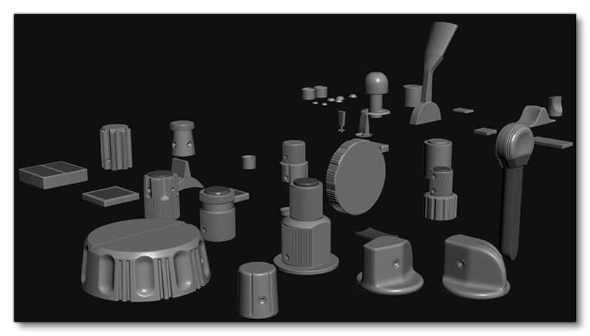
In order to achieve the best results, it will probably be necessary to create ultra-high-res geometry to bake normal information from. With a tool like Substance Painter it is possible to texture a lot of normal information when modelling, as shown in the following example high-res mesh for baking:
You can find more detailed geometry guidelines on the following page:
Instancing
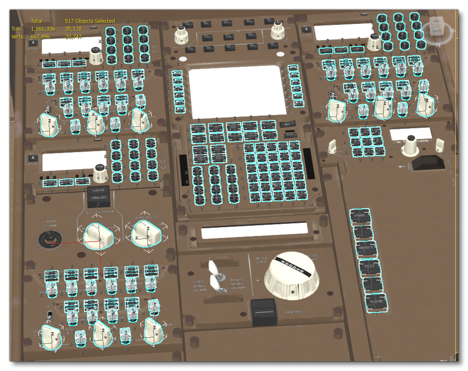
When creating your cockpit model we recommend that you use, where possible, instancing to generate "clones" of things like buttons, knobs or sliders. This means that instances of the same object will be rendered as a single batch and also be stored as a single object in memory, which reduces the GPU overhead required to render it in the game. The image below illustrates some of the elements of a cockpit that have been instanced:
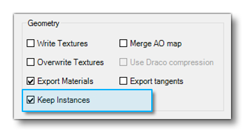
 When using instances and exporting the glTF, ensure that you have enabled the Keep Instances option in the Babylon Exporter in 3Ds Max:
Cabin Detail
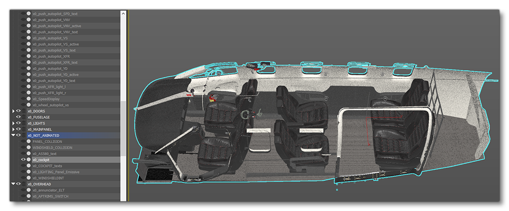
In some cases, it may be that there is part of the interior aircraft cabin that will be visible from the cockpit, and as such this should be modelled as part of the cockpit model:
 If the aircraft has a visible cabin, this - and all it's contents - should be placed in a separate group0 and called simply
 x0_Cabin (and x1_Cabin, x2_Cabin, etc... for all LODs):

Pilots
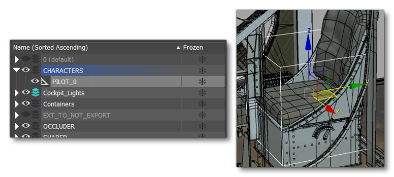
To ensure that the pilot and co-pilots will spawn correctly within the cockpit when it is used in the simulation, you simply have to do the following:
- Create a helper called
PILOT_N(where N is either 0 or 1, where 0 is the pilot and 1 is the co-pilot/instructor) - Place it on it's own layer called CHARACTERS (having it on it's own layer means you can choose which LOD to export with in the multi-exporter).
- Position the helper on the seat of the cockpit.
Object Breakdown
The following is a general list of the different objects that will be required to create the cockpit, and that should not be merged:
- All the animated and other interactive objects are separated -
- Inputs (buttons, knobs, levers, breakers…) with decals if there is any on it
- Pedals
- Yoke
- Doors
- Seat belts and harnesses
- Stairs
- Sun Visors
- Windshields and windows
- Lights
- Other glass objects
- Collisions
- Decals
- Occluder
- Various Dummies (pilots, lights, VR…)
In general the rest of the objects in the cockpit can be merged to create a single cockpit "shell":
Merging static and non-interactive elements is important as each object will be a "node" to load in the simulation, so by merging them you will reduce the amount of objects to load, which in turn reduces the draw calls, which result in better performance. This is especially important for large aircraft like airliners as they will have a lot of input objects that can't be merged, so trying to reduce nodes everywhere else is essential.