MODEL ANIMATION DEFINITIONS
This section is dedicated to the XML elements related to model animation. These elements can be used as part of the [model].xml file, or as a separate animations.xml file. If any animations are being defined for a single model then you would normally include these elements within the actual [model].xml, but if you wish to share animations across multiple models, then you would set up an animations.xml file, formatted as follows:
<?xml version="1.0" encoding="UTF-8"?>
<ModelInfo version="1.1" guid="<!-- GUID HERE -->">
<Animation>
<Event time="1" name="Event_Name"/>
</Animation>
<!-- FURTHER ANIMATION EVENT DATA HERE -->
<AnimGraph>
<DefaultState name="Default_State_Name"/>
<BlendTreeState name="Idle">
<Animations>
<Animation guid="<!-- GUID HERE -->" loop ="True/False" speed="1"/>
</Animations>
<Events>
<Event time="1" name="Event_Name"/>
</Events>
</BlendTreeState>
<!-- FURTHER BLENDTREE STATES HERE -->
<Transition start="Start_Animation" end ="End_Animation">
<Condition> <!-- RPN CONDITION HERE --> </Condition>
</Transition>
<!-- FURTHER TRANSITIONS HERE -->
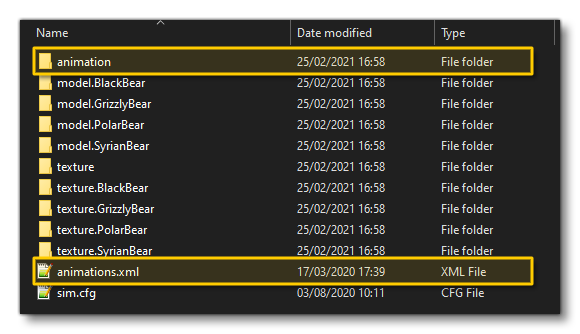
<AnimGraph>
</ModelInfo>This file would be placed in the same location as the sim.cfg file or aircraft.cfg that will be using the animations, and there should be an "animations" folder in the same directory, for example:
 Note that the elements listed here can also be used within the
 <Behaviors> element of the [model].xml to define animations as part of the Model Behaviors, or as part of a <Component> definition.
<Animation>
This element is the root entry of any behavior. It defines the name the of the model animation and the behavior it should be linked to. It can contain the <Event /> sub-element and has the following parameters:
| Attribute | Description | Type | Required |
|---|---|---|---|
name |
A unique name for the new animation. It should not contain any spaces or punctuation, but can contain underscores and numeric digits. | String | Yes |
guid |
The unique GUID for the animation. This is the reference the simulation will use to identify the animation, and must be in the format "{xxxxxxxx-xxxx-xxxx-xxxx-xxxxxxxxxxxxxxxx}", all lower case, e.g: "{12f06ee8-11ce-4e7b-a715-a9c5deb5352f}". |
String | Yes |
length |
This is used only for "Sim" animations, and exists for backwards compatibility. It is not necessary to specify this if you specify the <AnimLength> element of a <PartInfo> animation. |
Float | No |
type |
Defines the type of animation. Standard animations are simpler to define and not typically driven by aircraft controls. Sim animations are usually linked to Simulation Variables, see the section on <PartInfo> below for more information. |
Enum: "Standard" |
Yes |
typeParam |
This is used to set the animation play property for the different animation types. You can uses either or both of the available options, eg: typeParam = "Autoplay" |
String : "AutoPlay" - the animation will run when the object is rendered "Random" - the animation will be started at a random point along its timeline "FrameRate" - The FrameRate reference value, where the default value is 18fps. This is essentially a scalar of 1, so if you set the FrameRate to 36fps the animation would be played at double the speed, or at 9fps to play at half speed. |
No |
typeParam2 |
This parameter is used for "Sim" animations only and specifies which <PartInfo> to use for this animation. This is a legacy parameter, and as such should not be used. |
String | No |
<NodeAnimation>
This element is currently used for advanced "wingflex" bone animation. It animates the positions of several nodes in three dimensions. For this to have the desired effect, the nodes should be the joints of a skeleton that skins the wings and the nodes are hard-coded to a limit of 12 with the following order:
| Order | Node Position |
|---|---|
| 0 | the left wing bone closest to the center |
| 1 | in between |
| 2 | in between |
| 3 | the left wing bone furthest from the center |
| 4 | the right wing bone closest to the center |
| 5 | in between |
| 6 | in between |
| 7 | the right wing bone furthest from the center |
| 8 | the left wing engine pivot node closest to the center |
| 9 | the left wing engine pivot node furthest from the center |
| 10 | the right wing engine pivot node closest to the center |
| 11 | the right wing engine pivot node furthest from the center |
The element has the sub-element <Node /> and takes the following attribute:
| Attribute | Description | Type | Required |
|---|---|---|---|
type |
The type of node animation to use (currently only 1 type is available) |
Enum: "WingFlex" |
Yes |
<Node />
This self-closing element is a sub-element of <NodeAnimation> and is used to define the 12 different wingflex nodes on the model for the aircraft (one <Node /> element per wingflex node).
<AnimationEvent>
This element describes a moment in time when the animation reaches a certain point. Note that it is sensitive to the direction in which the animation changes, and by default an event only fires when an animation value increases. It can have <Time> and <IsNormalPlayback> sub-elements, and takes the following attributes:
| Attribute | Description | Type | Required |
|---|---|---|---|
EventName |
The name of the event, which can be used by other parts of Microsoft Flight Simulator 2020, like missions. |
String |
Yes |
AnimationName |
The name of the animation this event links to. | String | Yes |
<Time>
This is a sub-event of <AnimationEvent> and is used for setting the time - as a percentage of the animation duration - at which this event should trigger. An animation can have several <Time> elements, in which case the event will fire on all those occasions. Note that some animations contain several parts. For example, the gear animations have the retraction in the first half and the suspension in the second half. This element has no attributes.
<IsNormalPlayback>
This is a sub-event of <AnimationEvent>. If this is set to False (0), the animation event will trigger when the animation value decreases instead. The default value is True (1).
<AnimGraph>
This element is a container element that is used to hold the various elements used to define one or more animations for a model, as well as how those animations should transition together based on specific conditions. It can contain the following sub-elements: <DefaultState />, <BlendTreeState>, and <Transition>. Additionally you may also provide one or more <Layer> elements, but this is a beta feature and so should be extensively tested if used.
The AnimGraph system is mostly used by Living Thing SimObjects: a complex example would the airport Marshaller, while a more simple example would be an animal walking around. The <AnimGraph> will contain at least two or more <BlendTreeState> elements, each with a unique name. It will also contain a <DefaultState /> (that references a <BlendTreeState>), and one or more <Transition> elements to control the change between two blendtree states.
Each <BlendTreeState> has at least one animation - but can have more - and these animations can be used by several <BlendTreeState> elements if required. A <BlendTreeState> element also specifies whether an animation should loop or not, which means you can have two <BlendTreeState> elements for the same animation, with one looping while the other does not. Switching between these blendtree states is done using the <Transition> element, which must be specified for it to be possible to go from one blendtree state animation to another.
<DefaultState />
This is a self closing element that sets a default model animation state. The element should be included as part of an <AnimGraph> or a <Layer> and has a single attribute:
| Attribute | Description | Type | Required |
|---|---|---|---|
Name |
The name of the blendtree state that should be used as the default animation state for the model. |
String |
Yes |
<BlendTreeState>
This element is used to define one or more animation states that can be used for animating the model. These states can be blended together using the <Transition> element, and can have <Animations>, <Events> and <Value> elements used as sub-elements to further control how and when the animation will be played. This element is used within the main <AnimGraph> container or within a <Layer> and has the following attribute:
| Attribute | Description | Type | Required |
|---|---|---|---|
Name |
The name of the animation state that is being defined. |
String |
Yes |
<Value>
This element is used to set a value for the animation state. This is done using Reverse Polish Notation, for example:
<Value>(A:GROUND VELOCITY, METERS PER SECOND)</Value>
<Animations>
This is a container element for one or more of the <Animation> sub-elements and is used inside a <BlendTreeState> element. It has no attributes.
<Animation>
This sub-element defines how a single animation - based on the supplied animation GUID - should be performed. The attributes that control the animation within this element are:
| Attribute | Description | Type | Required |
|---|---|---|---|
guid |
The animation GUID to reference (as defined by the main <Animation> element). |
String | Yes |
loop |
Whether the animation should loop (True) or not (False). | Bool | Yes |
speed |
The animation speed scalar. When set to 1 the animation will play at the original speed. Lower values will slow the animation and higher values will speed it up, eg: 0.5 would play it at half speed and 2.0 would play it at double speed. | Float | Yes |
threshold |
This is the threshold value for choosing an animation based on the returned |
Float | No |
FireEventOnEnd |
This is used to notify the end of an animation for a <SimMission.PlayBlendTreeStateAction> to become "complete". This means that if the <SimMission.PlayBlendTreeStateAction> is set with <Immediate>False</Immediate>, it will wait until the end of the animations from the <BlendTreeState> element that do have this set to "True", before continuing to the next action. |
Bool | No |
<Transition>
The <Transition> element is a container element for the <Condition> sub-element and is designed to create a transition between two different <BlendTreeState> animations. This element is a child of the main <AnimGraph> or <Layer> elements.
When creating transitions between states, you can have them work in four different ways depending on the attributes and elements that are set for it:
- A transition without any
<Condition>element nor anExitTimeattribute will be considered as "manual". This means that it will only be executed when some code or script requests a different<BlendTreeState>and the following conditions are met: the requested state is the definedendstate of the transition, and the currently playing animation matches thestartstate animation. - The following are all considered as "automatic" transitions:
- A transition with a
<Condition>but without anExitTimeattribute will be automatically executed if the<Condition>resolves as true and thestartstate is the current one. - A transition with an
ExitTimeattribute and no<Condition>will be automatically executed when the animation from thestartstate reaches a certain ratio of the animation. For example, anExitTimeof 1.0 will start the transition immediately at the end of the current animation. A value of 0.5 will start at half the duration of the current animation. A value of 2.5 will start after two and a half (looped) iterations of the current animation. - A transition with both an
ExitTimeand a<Condition>will be automatically executed when both the<Condition>resolves as true and theExitTimevalue has been reached.
- A transition with a
NOTE: "Automatic" transitions cannot be controlled by code or script, and should only be used when the transition is expected to always happen after some time/condition, no matter what the circumstances.
Some notes on triggering transitions:
- when using the
<Condition>element, if the current state is thestartone from the transition, the code in the<Condition>is evaluated every frame, and if it resolves as true, then the transition triggers. - using a
<SimMission.PlayBlendTreeStateAction>in a mission/script file to ask an animation to go to state X. This will search for a transition going from the current state to state X, and will trigger that transition if it is found (if no such transition exists, the action will do nothing). - When using an
ExitTimegreater than 0, you are setting a "ratio" that will trigger the transition automatically once the animation from thestartstate has reached that far in the animation. For example:- if you set
ExitTime="0.5", the transition will trigger when the animation is halfway through, and the animation keeps going - blended with the new one - during the transition duration as usual. - if you set
ExitTime="3.0"- and the animation is set to loop - then the transition will automatically trigger after 3 loops.
- if you set
The element has the following attributes:
| Attribute | Description | Type | Required |
|---|---|---|---|
start |
The name of the start animation (the one to transition from), as defined by the <BlendTreeState> "Name" attribute. |
String | Yes |
end |
The name of the end animation (the one to transition to), as defined by the <BlendTreeState> "Name" attribute. |
String | Yes |
duration |
The duration of the transition, in seconds. | Float | No |
ExitTime |
The time ratio for when the transition should trigger (see the information given above for more details) | Float | No |
<Condition>
This element is for defining a conditional expression that will be evaluated every frame to see if the parent <Transition> should be triggered or not. The condition should be written using Reverse Polish Notation, for example:
<Condition>(A:SURFACE RELATIVE GROUND SPEED, METERS PER SECOND) 0.1 ></Condition>
<Layer>
IMPORTANT! This is a Beta feature and as such should be used with caution. If you have issues, please contact the developers.
This is an advanced feature that can be used to assign different blendtree states to different layers within the model and as such have various animations playing independently of each other. The intended use of the layers system is to have each layer corresponding to an independent part of the model, so that their animations do not conflict. For example, you could have a layer controlling the legs and lower body of a Human model, another layer for the arms and upper body, and a third layer for the head. Each layer could then be in a different state : legs walking or not, arms idle or doing some animation, face looking happy or sad or talking, etc...
This element can contain the following sub-elements: <DefaultState />, <BlendTreeState>, and <Transition>, and it has the following attributes:
| Attribute | Description | Type | Required |
|---|---|---|---|
name |
The name of the layer. | String | Yes |
weight |
This can can be used to determine how to blend several layers together if they happen to conflict with one another or with Model Behavior animations. Default value is 1. | Float | No |
<Events>
This is a container element for the <Event /> sub-element which is used to define animation events within a <BlendTreeState> element. It has no attributes.
<Event />
This is a sub-element of the <Events> container element - and also the <Animation> element - and is used to set the timing of specific animation events that are used in world scripts (usually for flora/fauna SimObjects in the world), or as events to be performed when an animation has ended (as used in <BlendTreeState> elements). It is a self-closing element that has the following attributes:
| Attribute | Description | Type | Required |
|---|---|---|---|
time |
The time that the event should trigger. This is a frame number, and should start from 0. | Integer | Yes |
name |
The name of the animation this event links to. | String | Yes |
<PartInfo>
This element is used to link animations and there should be one of these elements for every <Animation> of the type "Sim". The element takes no parameters, and is a container for multiple sub-elements: <Name>, <Copy>, <AnimLength>, <Animation>, <Parameter>, <MouseRect>. Please see the page model.cfg Examples for examples of how this element is used.
IMPORTANT! This - and the sub-elements it contains - is a legacy element and should not be used, nor is it required, for custom SimObjects made for Microsoft Flight Simulator 2020.
<Name>
This is a sub-element of <PartInfo> and is the name of the animation from the <Animation> element. This element has no attributes.
<Copy>
This is a sub-element of <PartInfo>. One <PartInfo> entry can serve as a template for another. For example if the two have very similar animations but reference a different variable, the second can copy the first, but a new <Variable> entry will override the first. This element has no attributes.
<AnimLength>
This is a sub-element of <PartInfo>. In FSX, this was the length of the animation in frames. In Microsoft Flight Simulator 2020, this variable is only used to scale the output of <Parameter> blocks that contain either <Code> or <Sim> sub-elements. The output divided by the <AnimLength> should be a value between 0 and 1, which is then multiplied with the length of the model animation to get the correct animation position. If the divided output value is not between 0 and 1, it will be clamped. This element has no attributes.
<Animation>
This is a sub-element of <PartInfo> and describes how the part will animate. It can contain the <Parameter> sub-element and has no attributes.
<Parameter>
This is a sub-element of either the <Animation> or <Component> elements and is a container element for <Code> or <Sim> sub-elements, with the optional <Lag> elements being available too. It has no attributes.
<Lag>
This sub-element of <Parameter> can be used to introduce a lag amount. A lag can be used so that a part will not jump instantaneously from one state to the next. Lag is measured in the maximum number of keyframes per second. So, for example: if the animation frame length is 50, and the lag is set to 400, the animation will take a minimum of 50/400 or one eighth of a second to complete.
<Code>
This sub element of <Parameter> can contain a reference to a script for evaluation.
<Sim>
This sub-element of <Parameter> must contain a <Variable> entry for the animation to reference, along with <Units>, <Scale>, and <Bias> entries.
<Variable>
This is a sub-element of <Sim> (and also <CallbackDragging>) and takes the name of the simulation variable being referenced. Note that the usual notation (A:Variable name) is simplified to just the variable name for this entry.
<Units>
This is a sub-element of <Sim> (and also <CallbackDragging>) and sets the units of the variable. The page on Simulation Variables lists all the available units: Simulation Variable Units
<Scale>
This is a sub-element of <Sim> (and also <CallbackDragging>) and is used to scale the value returned by the variable. The result is the offset into the keyframes, for example: a boolean value of 0 or 1 scaled by 50, will result in keyframe 0 being used for the FALSE state, and keyframe 50 for the TRUE state.
<Bias>
This is a sub-element of <Sim> (and also <CallbackDragging>). If the value returned and scaled does not fall into the desired range for the keyframes (for example, the range -50 to +50), then a bias can be added to all values to indicate which keyframe to use. A bias of 50 in this example will adjust the range to 0 - 100.
<MouseRect>
This is used within the model behavior <Template> and <Component> elements, and can also be seen as a sub-element of the deprecated <PartInfo>. It is a container element used to define how the user interacts with an animated part. It has no attributes and can contain the following elements:
<Cursor>, <HelpID>, <ToolTipID>, <MouseFlags>, <CallbackCode>, <CallbackDragging>, <CallbackJumpDragging>, <EventID>.
<Cursor>
This is a sub-element of the <MouseRect> element, and has no attributes. It is used to define the shape of the cursor when the mouse is over the rectangle. The contents of this element should be one of the following strings:
NoneNormalUpArrowDownArrowLeftArrowRightArrowHandCrosshairGrabGrabOpenTurnLeftTurnRightTurnLeft_SmallTurnRight_SmallTurnLeft_UpSideDownTurnRight_UpSideDownUpDownArrowsLeftRightArrowsDiagonalArrowsLockDynamicAnimTip
<HelpID>
This is a sub-element of the <MouseRect> element, and has no attributes. It takes the ID of the help string to display when the cursor is over the mouse rectangle. For more information, see the page on Help Text IDs.
<ToolTipID>
This is a sub-element of the <MouseRect> element, and has no attributes. It takes the ID of the tooltip string to display when the cursor is over the mouse rectangle. For more information, see the page on ToolTip Text IDs.
<MouseFlags>
This is a sub-element of the <MouseRect> element and holds one or more case-insensitive mouse flags that indicate when the <Behaviors> is to be triggered. The element has no attributes and will take one of the following strings:
LEFTALLRIGHTALLMIDDLEALLRIGHTSINGLEMIDDLESINGLELEFTSINGLERIGHTDOUBLEMIDDLEDOUBLELEFTDOUBLERIGHTDRAGMIDDLEDRAGLEFTDRAGMOVERIGHTRELEASEMIDDLERELEASELEFTRELEASEWHEELUPWHEELDOWNWHEELDOWNREPEATMOVEREPEATLEAVE
<CallbackCode>
This is a sub-element of the <MouseRect> element and allows for a range of calculations, assignments and the sending of key events to take place. This element can contain the following sub-elements and has no attributes: <XScale> / <YScale> / <ZScale>, <MinValue> / <MaxValue>, <IsRelative>, <DragAnimName>, <DragNodeName>, <DragAnimSynced>, <DragUseAnimLag>, <DragMode>, <DragScalar>, <DragFlagsLockable>.
<XScale> / <YScale> / <ZScale>
These are sub-elements of the <CallbackCode> and <CallbackDragging> elements and can be used to scales the delta X, Y or Z value for the mouse. The delta is the difference in screen co-ordinates between the current position of the mouse and the position when the dragging started.
<MinValue> / <MaxValue>
These are sub-elements of the <CallbackCode> and <CallbackDragging> elements and can be used to set the lower and upper limits of the value that will actually be sent with the key event.
<IsRelative>
This is a sub-element of the <CallbackCode> and <CallbackDragging> elements and has no attributes.
<DragAnimName>
This is a sub-element of the <CallbackCode> and <CallbackDragging> elements and has no attributes.
<DragNodeName>
This is a sub-element of the <CallbackCode> and <CallbackDragging> elements and has no attributes.
<DragAnimSynced>
This is a sub-element of the <CallbackCode> and <CallbackDragging> elements and has no attributes.
<DragUseAnimLag>
This is a sub-element of the <CallbackDragging> element and has no attributes.
<DragMode>
This is a sub-element of the <CallbackCode> and <CallbackDragging> elements and has no attributes. Will be one of the following:
TrajectoryDefault
<DragAxis>
This is a sub-element of the <CallbackCode> and <CallbackDragging> elements and has no attributes.
<DragScalar>
This is a sub-element of the <CallbackCode> and <CallbackDragging> elements and has no attributes.
<DragFlagsLockable>
This is a sub-element of the <CallbackCode> and <CallbackDragging> elements and has no attributes.
<CallbackDragging>
This is a sub-element of the <MouseRect> element and adding this entry allows for a more complex interaction with the part. The location where the user clicked and the current simulation value related to this part are captured, then when the user drags the mouse a set key event is triggered. The value passed with this key event is determined by the simulation <Variable>, and the <Scale> and <Bias> values. This element can contain the following sub-elements and has no attributes: <XScale> / <YScale> / <ZScale>, <MinValue> / <MaxValue>, <IsRelative>, <DragAnimName>, <DragNodeName>, <DragAnimSynced>, <DragUseAnimLag>, <DragMode>, <DragScalar>, <DragFlagsLockable>,.
<CallbackJumpDragging>
This is a sub-element of the <MouseRect> element and adding this entry allows for mouse interactions when an increment and decrement key event are required. It has the following sub-elements and takes no parameters: <XMovement> / <YMovement>.
<XMovement> / <YMovement>
These are sub-elements of the <CallbackJumpDragging> element and have no attributes. These elements contain the definition of the required mouse movement (in the X and Y directions), and can also contain the following sub-elements: <EventValueInc> / <EventValueDec>, <Delta>.
<EventValueInc> / <EventValueDec>
These are sub-elements of the <XMovement> / <YMovement> elements and have no attributes. They can be used to define the value to be sent as the increment or decrement.
<Delta>
This is a sub-elements of the <XMovement> / <YMovement> elements and has no attributes. It takes a value which is the mouse movement in screen co-ordinates required for one increment or one decrement key event to be triggered. By default movement to the right or up increments, but this can be reversed by entering a negative delta.
<EventID>
This is a sub-element of the <MouseRect> element and can also be a sub-element of the <CallbackDragging> element.
When used with the <MouseRect> element, it stores the ID of the event that will be triggered if the mouse is clicked over the mouse rectangle. Alternatively a custom numeric event can be defined (in the range 0x11000 to 0x1FFFF), to be picked up by a gauge handler written in C++. The element has no attributes.
When used with the <CallbackDragging> element, this should be a set key event and not a key event that toggles or increments or decrements.