panel.cfg
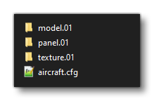
The panel.cfg file is a critical file when it comes to defining aircraft, and would go in the panel folder in the root directory for the aircraft (along with the model, sound, etc... folders). This file is used to create the different virtual cockpit elements by referencing one or more XML, HTML, or C/C++ gauges.
If the panel.cfg file is for a livery or a variation, then it's worth noting that it should go in a folder that has been named using the following convention: panel.<name>, where <name> is an identifier for your livery/variation.
 This file will also need to be referenced in the
 aircraft.cfg under the [FLTSIM.N] section panel parameter, eg:
[FLTSIM.0]
title = "My Aircraft Variant"
model = "01"
panel = "01"
sound = "01"
Below you can find information on the different sections used in the panel.cfg file as well as what parameters and values are expected within them.
[VARIATION]
This section is only used when you are creating an aircraft that references another "base" aircraft, for example when creating a livery. Basically the panel.cfg file for a livery/variation will follow these three rules:
- if the livery/variation doesn't include a
panel.cfgfile then the "base"panel.cfgfile will be inherited and used. - if the livery does have a
panel.cfgfile, and doesn't have theoverride_base_containerparameter (or theoverride_base_containerparameter is set to 1) then it needs to contain ALL the required data as it will override everything in the "base"panel.cfg. - if the livery has a
panel.cfgand also hasoverride_base_containerset to 0, then it will use the "base" file and add in the extra sections from the livery/variation (or overwrite any sections that already exist in the "base" file).
| Parameter | Description | Type | Required |
|---|---|---|---|
override_base_container |
Whether to override the "base" panel config file or not. By default this is 1 (TRUE). |
Integer |
No |
[Window Titles]
IMPORTANT! This section is legacy only and has no effect on Microsoft Flight Simulator 2020. As such it can be omitted.
This section permits you to give a title to each of the different panel windows defined in the config file. Windows are numbered from 0, and each [WindowN] section, should have it's own corresponding title parameter in [Window Titles]. The parameters available to this section are as follows:
| Parameter | Description | Type | Required |
|---|---|---|---|
WindowNN |
The name (title) of the panel window defined in the config file for the aircraft. This string is used as the display name for the panel in various places within Microsoft Flight Simulator 2020 so you should ensure that the label you use for each window is appropriate. Also note that the order in which you assign panel windows does not matter, so long as you start with Window00. |
String |
Yes |
[WindowNN]
IMPORTANT! This section is legacy only and has no effect on Microsoft Flight Simulator 2020. As such it can be omitted.This section permits you define a panel window for gauges within an aircraft. NN is the window number (numbered from 00) and each new window section should increment by 1 (so Window00, Window01, Window02, etc...). Available parameters are:
| Parameter | Description | Type | Required |
|---|---|---|---|
file_1024 |
The bitmap file to use when the screen width has been set by the user to more than 800. | String | No |
size_mm |
A definition of the unit size used for placing and sizing gauges on this panel. For example, if the If |
1D table of 2 Floats (see Data Types for more information) |
No |
window_size |
The percentage of the screen to be taken up by window, from 0 to 1. If this is set, the size of the main panel is ignored for this panel and size_mm becomes irrelevant for determining the size of the panel window (note that size_mm is still used for calculating the relative sizes of the gauges within the window). |
Float |
Yes |
windowsize_ratio |
Determines the width of a panel window as a ratio of the client area of the main window. If not specified, 1.0 is the default. | Float | No |
visible |
Set to 0 if the panel is not visible by default. The default is 1 (visible). | Bool | No |
update_rate |
This parameter can be used to change the default update rate, in hertz. The default update rate is 18hz, and note that this is the default rate for the whole panel, and this can be overridden by the update rate for individual gauges. | Float | No |
position |
Specifies the relative position of a panel window to the main window, expressed as an integer value. Default value is 7. |
Integer:
|
No |
background_color |
Use for a background created with no background bitmap. Use 0,0,0 for a transparent background. |
1D table of 3 Floats (see Data Types for more information) |
No |
alpha_blend |
The percentage (from 0.0 to 1.0) to blend the panel window with the background scene when the panel is docked. | Float | No |
ident |
Specifies a unique identifier to define the panel window. If your panel windows description does not fit any of the enum values listed, use any number between 10000 and 19999 (lower and higher numbers are used internally). There should be a |
Enum:
|
Yes |
gaugeNN |
Specifies which gauge file to load and the X,Y position of the gauge. The Panel system starts loading gauges from gauge00 until it reaches gauge99. After that, it loads gauge100, gauge101, and so on until it finds a break in the progression. This comma-delimited parameter exists primarily to specify which gauge DLL file to load and the X, Y position of the gauge, in millimeters. This will override the The basic format is: where:
Note that if you have set |
1D table of mixed values (see Data Types for more information) |
Yes |
draw_orderNN |
Instructs the renderer to draw certain sets of gauges in a specific order. In any draw order list, the gauges are drawn in that order. For example:
This simply means gauge50 is drawn before gauge60. |
1D Table of Floats (see Data Types for more information) |
No |
zorder |
Determines the order of appearance of the panels on the screen. Takes values from 0 (bottom) to 100 (top). | Integer | No |
[VCockpitN]
The [VCockpitN] sections provide you with a way to define the different virtual cockpit panels. Each panel should have a single [VCockpitN] entry, where N starts at 1 and each new entry increments it by one, without skipping any values. Note that for a correct VCockpit setup, each entry must have at least one gaugeNN or htmlgaugeNN parameter set up.
The parameters available in this section are as follows:
| Parameter | Description | Type | Required |
|---|---|---|---|
size_mm |
A definition of the unit size used for placing and sizing gauges on this panel. For example, if the size_mm is 200 x 200 and a gauge's size is 50, 50, it will take up 1/16th (¼ x ¼) of the panel window. If no size_mm is defined, the size of the panel's background bitmap (not the gauge's background bitmap) will be used. If no background bitmap is defined, a default size of 100 x 100 is used. |
1D table of 2 Floats (see Data Types for more information) |
Yes |
pixel_size |
Sets size of window in pixels. If not set, and sizeable is false, window pixel size will be set to background image size. If size y is set to 0, it will be generated from the aspect ratio of background file. If no background file is used y will be set equal to x. |
1D table of 2 Floats (see Data Types for more information) |
Yes |
texture |
This is the material ID of the screen where the instrument will be drawn. To create a gauge that has no render context use "NO_TEXTURE" as the material ID (see the Note For Invisible Gauges for more information). IMPORTANT! Previously - in FSX - this string needed to be preceded with a |
String | Yes |
background_color |
Use for a background created with no background bitmap. Use 0,0,0 for a transparent background. |
1D table of 3 Floats (see Data Types for more information) |
Yes |
hud |
This parameter provides a way to offset the HUD texture UVs on the quad mesh that displays it. The parameter requires 5 input values in the following format: hud = is_hud, yaw_offset (or displace_x), pitch_offset (or
When the
When the
|
1D table of 5 Floats (see Data Types for more information) |
No |
render_on_screen |
This parameter provides - when supplied - a way to render the VCockpit panel directly to the screen at a given position. The parameter requires 7 input values in the following format: render_on_screen = posX, posY, width, height, xoffset, yoffset, cameraFlag, hideInVR
The following example would be used to display a panel in the center of the screen when using the cockpit camera: render_on_screen = 0.5, 0.5, 0.5, 0.5, 0.5, 0.5, 0.5, 1, 1 NOTE: The width/height should be set to a 16:9 aspect ratio to ensure correct support in VR. |
1D table of 6 Floats and 1 Integer (see Data Types for more information) |
No |
emissive |
Specify whether the gauge is emissive or not. This is set to 1 (TRUE) by default, so use 0 (FALSE) to disable. | Bool | No |
backlight |
Specify whether the gauge is back-lit or not. This is set to 0 (FALSE) by default, so use 1 (TRUE) to enable. | Bool | No |
gaugeNN |
Specifies which XML/WASM gauge file to load and the X,Y position of the gauge. The Panel system starts loading gauges, starting from gauge00 until it reaches gauge99. After that, it loads gauge100, gauge101, and so on until it finds a break in the progression. This comma-delimited variable exists primarily to specify which gauge file to load and the X, Y position of the gauge, in millimeters. This will override the The basic format is: where:
Note that if you have set |
1D table of mixed values (see Data Types for more information) |
No (Yes if no |
htmlgaugeNN |
Specifies which HTML gauge file to load and the X,Y position of the gauge. The Panel system starts loading gauges, starting from htmlgauge00 until it reaches htmlgauge99. After that, it loads htmlgauge100, htmlgauge101, and so on until it finds a break in the progression. This comma-delimited variable exists primarily to specify which gauge file to load and the X, Y position of the gauge, in millimeters. This will override the The basic format is:
where:
Note that if you have set |
String |
No (Yes if no |
Note For Invisible Gauges
It is possible to create an "invisible" gauge context that will not be rendered - but will still run - by providing "NO_TEXTURE" as the material code for the texture and by setting the size to (1,1), as shown in the example below:
[VcockpitNN]
size_mm      = 1,1
pixel_size   = 1,1
texture      = NO_TEXTURE
htmlgauge00  = MyGauges/MyGaugeManagers/Manager.html, 0, 0, 1, 1
This is useful for creating "manager" or "data" gauges which only exist as a means to monitor something, or to move and process data, and which do not require any visual representation within the virtual cockpit displays.
[VPaintingN]
This section controls the drawing of registration numbers by the aircraft livery. Available parameters are:
| Parameter | Description | Type | Required |
|---|---|---|---|
size_mm |
The size of the texture to use, given as width,height. 1mm corresponds to 1 pixel of the texture image. |
1D table of 2 Floats (see Data Types for more information) |
No |
texture |
This is the material ID of the texture to use for the livery painting. IMPORTANT! Previously - in FSX - this string needed to be preceeded with a $ sign. However in Microsoft Flight Simulator 2020 this should not be used as it is now used to indicate to the engine that the material is a collision material, which is obviously not the case for livery text. |
String | No |
location |
Where the texture should be located on the aircraft. |
Enum: exterior interior |
No |
paintingNN |
The path to the HTML that defines the number look/layout. To use the default settings, please use the following path: Registration/Registration.html At it's most basic the full path should look like this: paintingNN=[html_file_path]?optionalParameter, X, Y, W, H Here you give the path, then a comma separated list for the dimensions of the area to paint. The area is defined using the relative (x,y) coordinates to draw from, plus a width and a height . Note that the maximum for the width/height values should be the values defined in the
Additional settings can be added to the path like this: painting00=Registration/Registration.html?font_color=0xe6ed01&stroke_size=120&stroke_color=0x3be0db, 0, 0, 2048, 512 The full list of settings that can be added in this way are:
All colours can be either a CSS predefined color like "red", "black, "blue" or a hexadecimal color code like "0xFF00FF".
|
String | No |
[Default View]
This section controls the default view for the default 3D window. Available parameters are:
| Parameter | Description | Type | Required |
|---|---|---|---|
X |
Specifies the X position of the default 3D window. | Float | No |
Y |
Specifies the Y position of the default 3D window. | Float | No |
SIZE_X |
Specifies the width of the default 3D window. | Float | No |
SIZE_Y |
Specifies the height of the default 3D window. | Float | No |
[Color]
This section controls the default color lighting settings. The Day and Night colors effectively determine the maximum and minimum brightness of the panel. The Luminous value specifies the color that can be applied to the luminous sections of the gauges. Available parameters are:
| Parameter | Description | Type | Required |
|---|---|---|---|
Day |
The lighting color applied during daytime (comma separated list where each item is a colour component from 0 to 255: R,G,B). |
1D table of 3 Floats (see Data Types for more information) |
No |
Night |
The lighting color applied at night (comma separated list where each item is a colour component from 0 to 255: R,G,B). | ||
Luminous |
The lighting color applied to gauges that are luminous (comma separated list where each item is a colour component from 0 to 255: R,G,B). |