DEBUG LODs
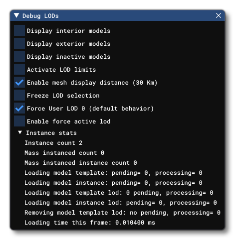 This window is opened from the DevMode Debug menu, and can be used to help debug the different LODs used by the models in a scene. This window has the following options:
-
Display Interior Models
Selecting this will display information about the interior model LODs currently being rendered. This will also show some Additional Options.
-
Display Exterior Models
Selecting this will display information about the exterior model LODs currently being rendered. This will also show some Additional Options.
-
Display Inactive Models
This option can be used to display the LOD details for "inactive" models, and it will only work when you also have Display Exterior Models enabled. An "inactive" model is one that the simulation has hidden from the scene, either because it is outside of the LOD range or because the current graphics settings have disabled it. They will usually be shown with cyan text and a LOD level of -1:

-
Activate LOD Limits
This option activates LOD limits, enabling you to preview the LOD system (described here: ). Note that this should be activated before initialising a flight.
-
Enable Mesh Display Distance
This option permits you to toggle on/off the mesh display distance. When on meshes will only be displayed up to a distance of 3km from the camera. When off the display distance is essentially infinite.
-
Freeze LOD Selection
When enabled, LOD selection will be frozen and no objects in the scene will update it's LODs. This permits you to set a LOD level for an object based on the camera position, freeze the LODs, and then move the camera closer to get a good look at how the LOD model looks in scene.
-
Force User LOD 0
This option will be on by default and will force the user aircraft to always show LOD 0 (the most detailed). Disabling this option will permit the user aircraft to go through the available LODs when you change the exterior camera.
-
Enable Force Active LOD
Enabling this option will show a LOD slider:
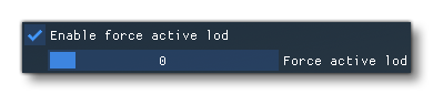 Changing this slider will alter the LODs for all objects being rendered, permitting you to check out lower detailed LODs even when the camera is right next to the object:

-
Instance Stats
This section, when expanded, shows the status for the different object instances being loaded and/or processed currently for the camera view.
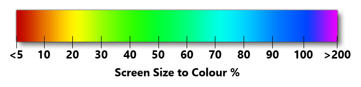
Note that the text (and bounding spheres) used to display LOD information will be colored to give a visual representation of this value, using the following scale:
 NOTE: This value will be affected by the Objects Level Of Detail setting from the General Options of the main simulation menus.This color will be shown except when the LOD Limits options are activated, in which case the text and bounding spheres will be colored based on how optimised the LOD values are, where:
- RED - The LOD is unoptimised and needs to be fixed
- ORANGE - The LOD is borderline optimised, but may have issues
- GREEN - The LOD is optimised
Additional Options
If you enable Display Interior and/or Display Exterior Models, then you will be presented with the following additional options:
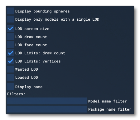
The options available here are:
-
Display Bounding Spheres
When this option is enabled, "bounding spheres" will be shown for all the models. These spheres are used as part of the screen size calculations as well as other internal calculations, and are a good way to visualise the approximate size and position of objects.
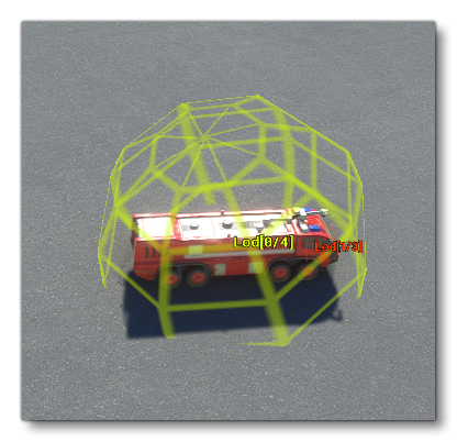 The color of the bounding sphere is a visual representation of the approximate LOD screen size following the same scale as that shown below in the LOD Screen Size description.
-
Display Only Models With A Single LOD
Selecting this option will change the debug display to only show those object instances with a model that has only a single LOD. This can be used to pinpoint objects that may be unoptimised for the simulation.
-
LOD Screen Size
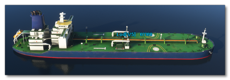
When this is enabled, there will be a value shown beside the LOD data for each object instance visible:
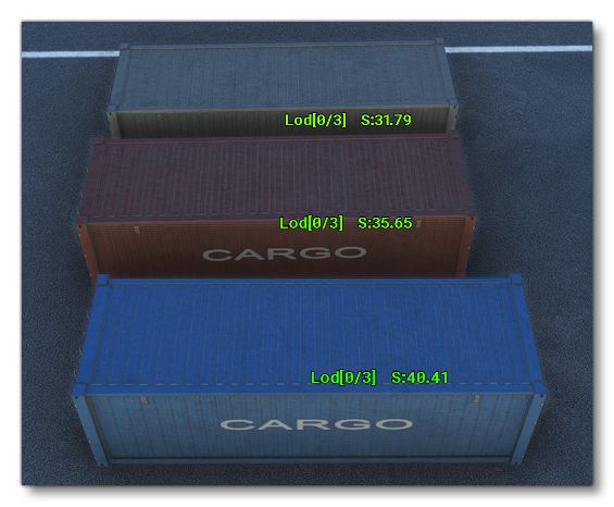 This value is the approximate size on screen for the object based on the bounding sphere (and not the object model). The value is calculated as a percentage.
-
LOD Draw Count
This will draw the current draw count for each LOD in the scene:
-
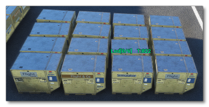
LOD Face Count
This option will add the model LOD face count to the display:
-
LOD Limits: draw count
Enabling this will show the draw count for the currently displayed LOD as well as the maximum number of draw calls for that LOD. Draw counts are influenced by the number of vertices and the number of materials that are associated with an object (although there may be other factors too).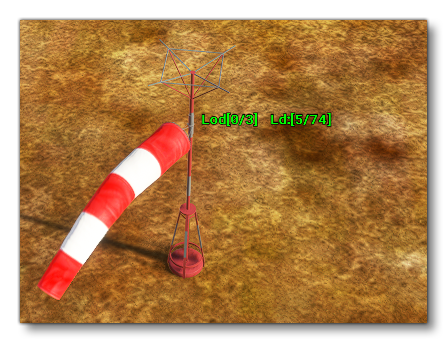
-
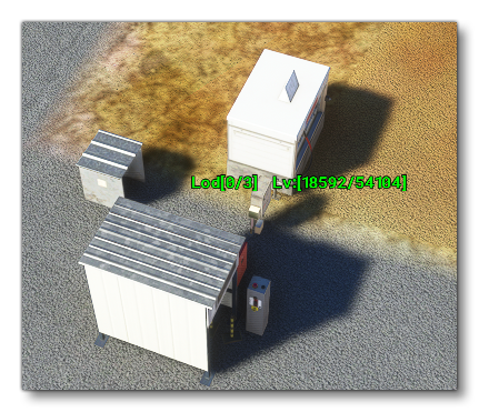
LOD Limits: vertices
Enabling this will show the the number of vertices for the currently displayed LOD as well as the maximum number of vertices for that LOD.
-
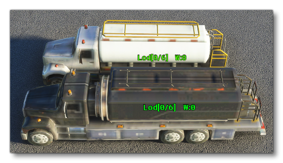
Wanted LOD
When enabled, this option will show the LOD that is to be loaded for each instance for it's LOD level:
-
Loaded LOD
This option, when enabled, will show a bitmask for the different LODs available to the model. Each value of the bitmask represents a LOD level, and if it is 0, the LOD is not currently loaded, while if it is 1, the LOD is loaded in memory:
-
Display Name
Using this option you can display a name for each of the object instances being displayed. When you enable this, you can choose from one of 4 options:
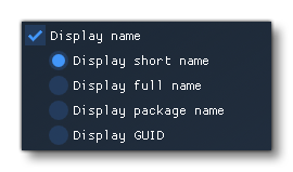
- Display Short Name: This will show the "short" name for the object, taken from the XML filename.
- Display Full Name: This shows the short name along with the path to the package where the file is stored.
- Display Package Name: This will show the package name that has the object in it.
- Display GUID: This will show the GUID for the object.