ANIMATING THE LANDING GEAR
In this section we'll go through some of the types of landing gear and explain briefly how they should be animated.
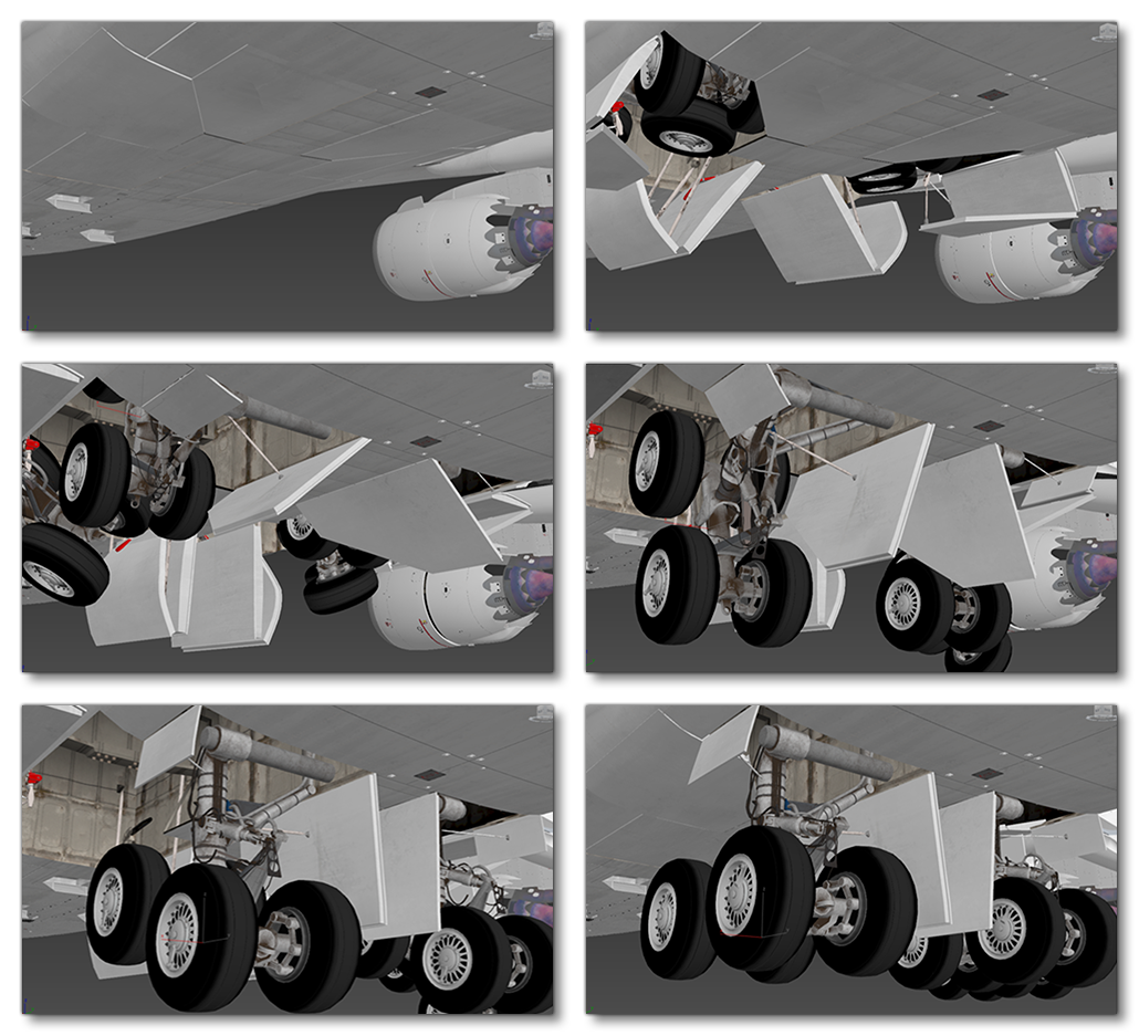
When modelling the landing gear, it should fold out and move exactly as it does in the real world. You should take great care to ensure that the various component parts of the plane are all modelled and set up correctly. The following image sequence shows what would typically be expected of the animation:
Animations
The animation for landing gears is split into two parts for every type of aircraft, including aircraft with retractable gears see for additional information). So, the first part of the animation is for extending the gears (or positioning the non-retractable gears), and the second part is for the gear compression. Essentially, landing gears are 50% gear position, and 50% compression.
NOTE: Create as many helpers as you need to animate all elements in the landing gear, and before creating the animation, make sure to duplicate all helpers you created for one gear and mirror them to get exactly the same helpers for the second gear, so that a single animation is applied to bothe the left and right gears.
When animating the landing gear and any associated parts of the airframe (like wheel covers, etc...) you can use constraints: LookAt, InverseKinetics, etc... Also make sure that there is no penetration between the different airframe nodes as you animate them (which can be a common issue when using constraints). Also consider that there can be some nodes that will benefit from Skinning on the gear, like cables.
Non-Retractable Landing Gear Key Frames
For non retractable landing gear the first keyframe (frame 1, 0%) would be the same as the "neutral position" keyframe, as would the 50% keyframe. The frames from 50% to 100% would be the in between frames from neutral (50%) to fully compressed (100%). For example, if the compression takes 50 frames your total animation would be 101 frames comprised of:
- frame 0: neutral position
- frames 1 to 51: static landing gear in neutral position
- frames 51 - 101: landing gear compressing from neutral to fully compressed, as shown in the image below
Retractable Landing Gear Key Frames
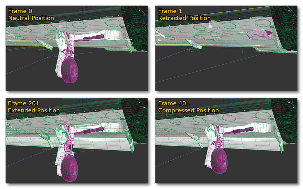
If your aircraft has retractable landing gear then the same rules outlined above still apply, ie: your animation is split into two parts with the last 50% being the landing gear compression. Only this time, the first fifty percent should be the frames showing the landing gear retracting. So, let's say our animation was 401 frames long, it would be comprised of:
- frames 0: neutral position
- frames 1 to 201: landing gear being extended animation, from fully retracted, to fully extended
- frames 201 - 401: landing gear compressing from neutral to fully compressed
 It should be pointed out that between these keys you can adjust the animation by adding inbetween keys, smoothing the movement and making this animation more realistic and functional.
Left / Right Landing Gear
To illustrate how you can animate the landing gear, we'll take a look at just the right side, since the same principles will be applied equally to the left, and the front/rear center gears.
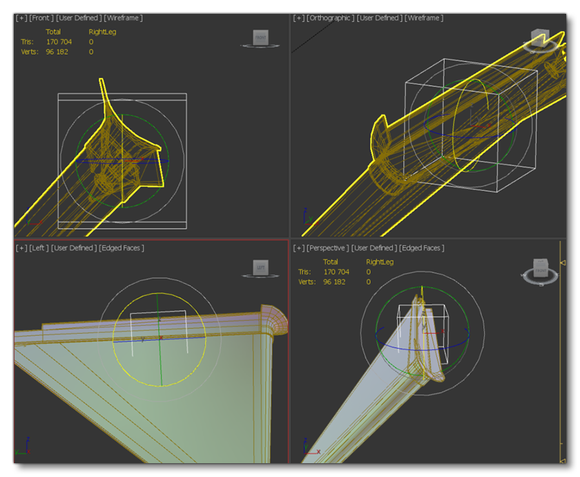
To start with, we create a new helper and name it RightLeg and link it to HIPS. We then place this new helper at the junction between the landing gear and the fuselage (where the deformation will happen). On our example aircraft, we need to align the helper with the fuselage along the rotational axis of the deformation, as this will give a good compression and correct movement for the gear, like this:
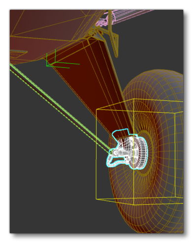
We'd then link the wheel helper RightWheel with the the the RightLeg helper, so that the wheel moves with the right leg object. You can then go ahead and link statics objects to the RightLeg if they don't need to be skinned:
You can then go ahead and use Skinning for the different parts of the landing gear which that you want to deform during landing and take off. Use RightLeg and HIPS helpers to skin the appropriate meshes.
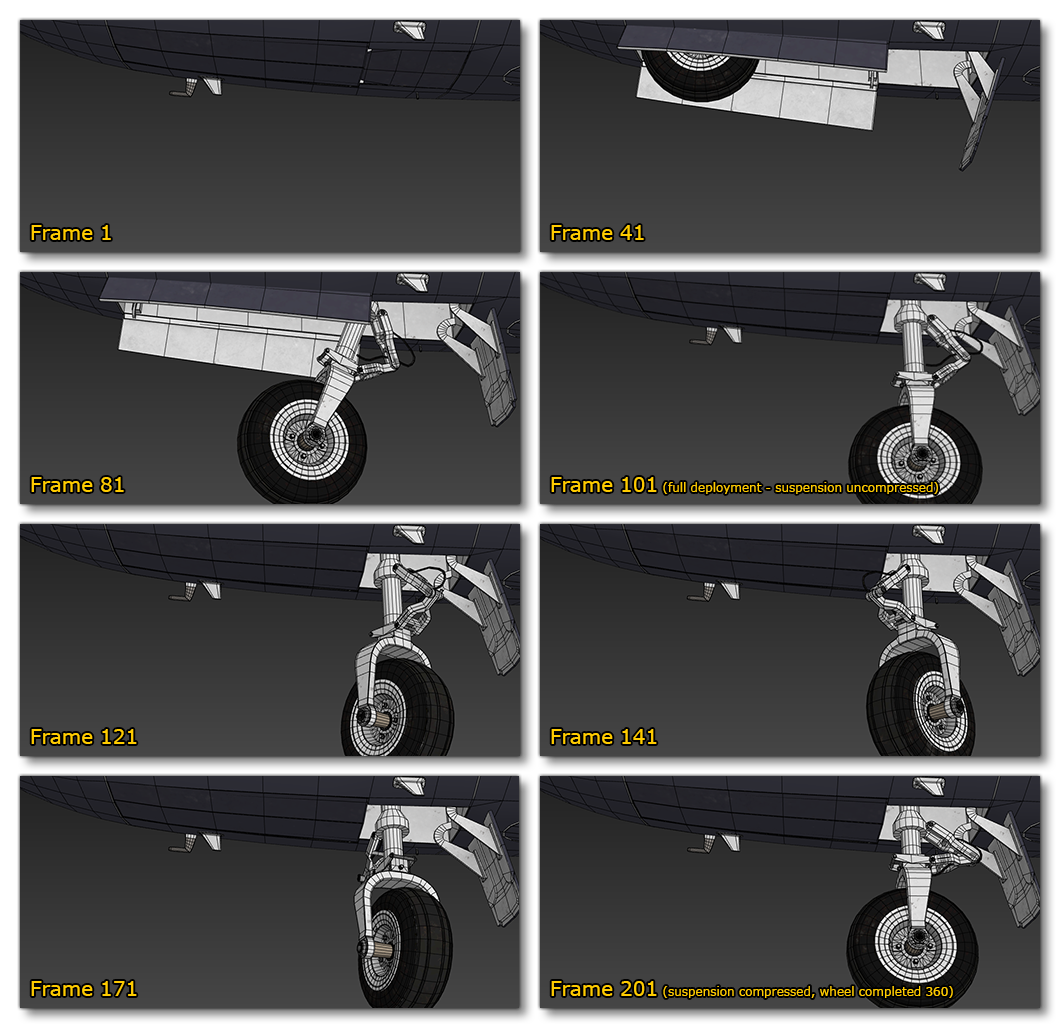
Front Landing Gear
With the front landing gear, it would be set up using the same process as for the others, but we need to also add steering. For that we have to rotate the front fork a full 360 degrees in a clockwise direction (note that if you have arms/pistons attached to the front fork you'll also need to add a look-at constraint). As a visual reference, the following images show how this would look for a landing gear animation of 200 frames: