ANIMATIONS OVERVIEW
At this point in the process you should have the airframe modelled (fuselage, wings, tail) and be ready to add in the parts that you will be needing to animate within the simulation. This will include the landing gear, flaps, ailerons, rudder, doors and other things depending on the aircraft you are modelling. Essentially, all the movable parts of the plane should be animated, and as such they should be modelled with this in mind.
On this page we give a brief overview of some of the things that should be considered before starting the animation process. Subsequent pages will go into more detail on how the animations should be set up within your modelling program.
IMPORTANT! As you work on animations, you will need to add them into the Babylon JS Animation Groups window for them to be exported correctly. Please see here for more information: Animation Groups.
General
Animations in Microsoft Flight Simulator work with percentages. What this means is that all animations that are imported into the simulation can use an arbitrary number of frames which will be interpolated between 0% (first frame) and 100% (the last frame).
The simulation can interpolate both linear and curve animations, however we highly recommend that you use linear animations for everything. For example, if you want to animate needles or knobs and they need to do 360° rotation, then you will need to animate it in linear, to avoid unwanted visual acceleration and deceleration. This acceleration/deceleration in the animation would be due to the smooth curves between keys and as a consequence it will not show you the right position of the needle.
Setup
When preparing 3DS Max for your animations, we recommend that you set up the Time Configuration as follows (you can access this window by right-clicking on the Play button):

- Time Display - Check the "Frames" option.
- Playback - Check the "Real Time" option, and set the "Speed" to x1.
- Animation - Here you will need to set your timeline "Start Time" and "End Time" values. Be sure to set enough frames on your timeline to animate everything in your cockpit / airframe. Note that there is no need to edit the frame count, as normally it will automatically update with your modifications in the Start and End values.
Rigging
To animate the parts of the airframe, we use helpers - dummies and parenting - as a rig. Rigging is a technique in animation where an object is represented in two parts : the mesh and a hierarchical set of bones (helpers), essentially a virtual armature to animate
meshes.

At this point, you will have the airframe meshes in folders labelled by LOD, eg: x0, x1 etc… However, you don't want to create your rig in those layers because you we want it to be relative to all LODs. So, you should make a new layer called "Shared" or something similar and all bones will be placed in this layer.
To animate additional mechanisms used by the different parts of the aircraft, you will need to "helpers", which you'll be adding into a group called PLOT. PLOTS are children of the different animation helpers and will be used to constrain meshes without animating them. So, in the "Shared" layer you would make a new "PLOTS" layer, and then in that layer you would create the required helpers.
We also need to create a root helper, which we'll call HIPS. For that you need to click the Helpers button ![]() in the Create window, select Point, select Box, and finally name it HIPS. You should then click on the viewport to validate and create the point, ensuring that position is reset to [0, 0, 0].
in the Create window, select Point, select Box, and finally name it HIPS. You should then click on the viewport to validate and create the point, ensuring that position is reset to [0, 0, 0].

When it comes time to start animating, be sure to create the animations using the linear in/out tangents:
 It is also of vital importance that the animations are set up without using groups or mirroring objects as - although this may work in 3DS Max - it will not work correctly once the aircraft is imported into Microsoft Flight Simulator.
NOTE: If you are thinking about using skinning, this should only really be required when adding wires and/or cables and for the wingflex, which is discussed in more detail here.
Frame Convention
It is important to note that when we discuss animations in this document, we will always be referring to animations starting on frame 1. This is because the general convention that we recommend is that frame 0 is used as the "t-pose" or "neutral position" frame, where you set up the model to look as it would when parked on the runway. This is important because certain animations (for example Landing Gear) require a specific number of frames, and the value does not include frame 0. So, to use landing gear as an example: for landing gear you need an even number of frames for the animation - say 100 - but you'd have an odd number of total frames - 101 - because you would also have frame 0.
Control Surface Details
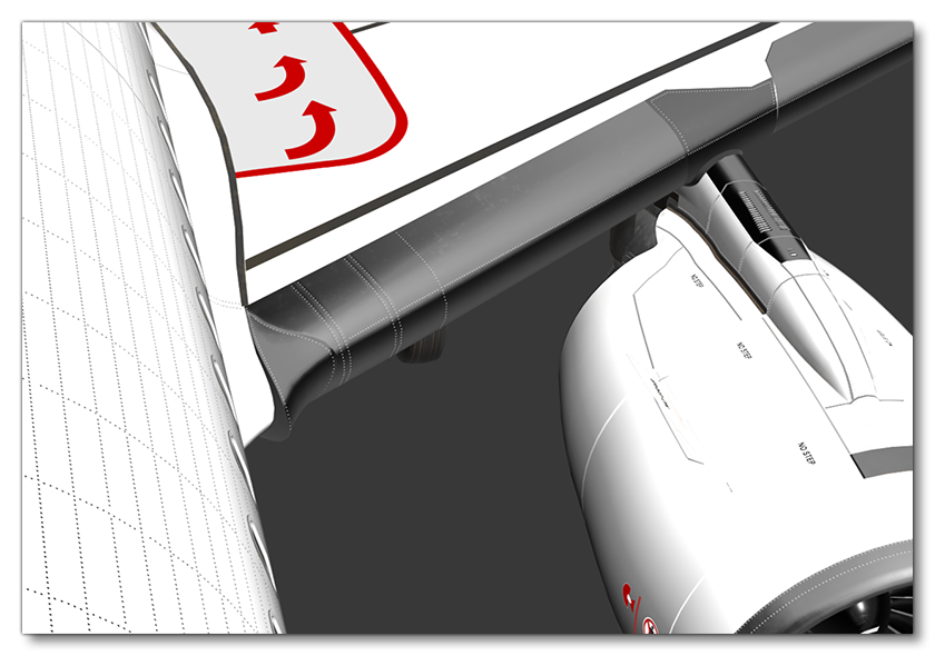
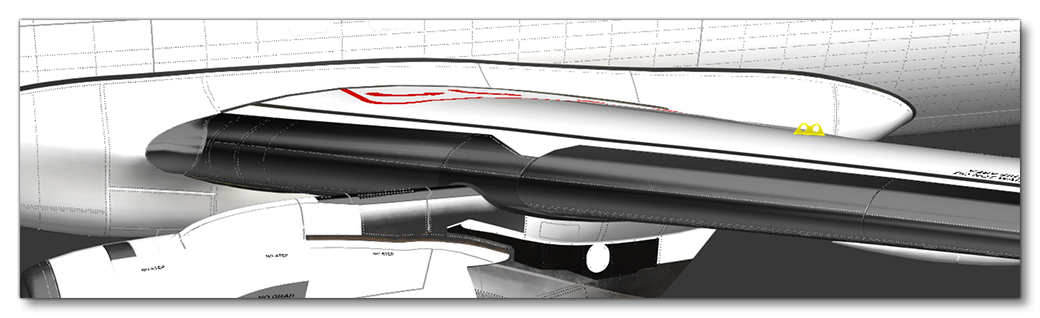
When modelling the moving parts of the aircraft, keep in mind that what's under and around them will be visible to the user at some point too, and as such detail needs to be modelled in the appropriate places. The example images below show how this is handled for flaps (mouse over the images to see before/after animation images).


General Process
The following images illustrate the general process for creating control surface animations, using flaps on a small aircraft as an example.
- Isolate the part you want to animate in the model:

- Create two point helpers:

- Snap each point to the "best" (most logical) position, as shown:

- Select one point then use the "LookAt Contraint" to constrain it to the other point:

- Assign the flap pivot to the point which has a LookAt Contraint on position and rotation:

Skinning
To animate certain airframe features, we can also use skinning. When skinning it's worth keeping the following details in mind:
- Before starting, take a good look at the real mechanisms to understand all the possible movements and how they work.
- When modelling, all the nodes used to skin the object have to be in the same hierarchy, but the skinned object does not need to be in the hierarchy.
- Pay attention to avoid penetration of the models with each other.
- Skinned items do not need to be added to Babylon Animation Groups.
- Checking "Show all Envelopes" can be helpful if you skin with vertices.
- The "Bone Affect Limit" MUST BE 4.
- Make sure that the skinned mesh node itself is part of the bone hierarchy. When a skinned mesh is moved with bones that are somewhere else completely in the hierarchy, it can cause an issue where the skinned mesh disappears when looking at it because the bounding box used for camera frustum culling is in a completely different location from the vertices. Having the skinned mesh node as part of the hierarchy means that the bounding box will move along with it and prevent the issue from happening.
To illustrate these points we'll be looking at using skinning to animate some cables that connect the Elevator Trim to the Elevator, and then the Elevator to the Fuselage.
To start with, we'll select the mechanism that we want to skin, in this case some cables. We then go to the Modify window in 3DS Max and select Skin from the modifier list:

The skin now needs to be set up and in general you'd be setting it up the same way for everything and not just for this elevator cabling. So, to start with, in the Advanced Parameters we set the Bone affect limit to 4:

Then in the Display section, we select Show no Envelopes:

Finally, in the general Parameters, you need to go to the bones section and click Add then select the bones to use. In our example these would be some PLOTs we'd have created earlier, for example: ElevatorTrim_Aux1 and ElevatorTrim_Aux2.
 Now you would edit the skin, keeping it simple while being as workable as possible. You can then repeat this process for any other mechanisms.

As a further example of skinning, you may want to connect a mechanism or cable to the fuselage or some other static element of the airframe mesh. With our elevator example, we have a cable that connects the trim to the main elevator, and then another cable from the elevator to the fuselage.
For the cable to the fuselage we just need to skin it with two bones:
ElevatorTrim_Aux[N]- the one moving with the Elevator - which is the part of the cable on the elevator and will move along with it.- HIPS - the part of the cable that links to the fuselage and that will not move.
Specific Airframe Parts
Now that you know the general process, you can continue on to the following pages that explain how to animate each of the essential airframe parts in more detail:
- Animating Ailerons, Flaps and Spoilers
- Animating The Elevator
- Animating The Rudder
- Animating Landing Gear
- Animating Wheels