ANIMATING THE RUDDER
This page goes through the steps needed to animate the rudder of the aircraft.
Basic Animation
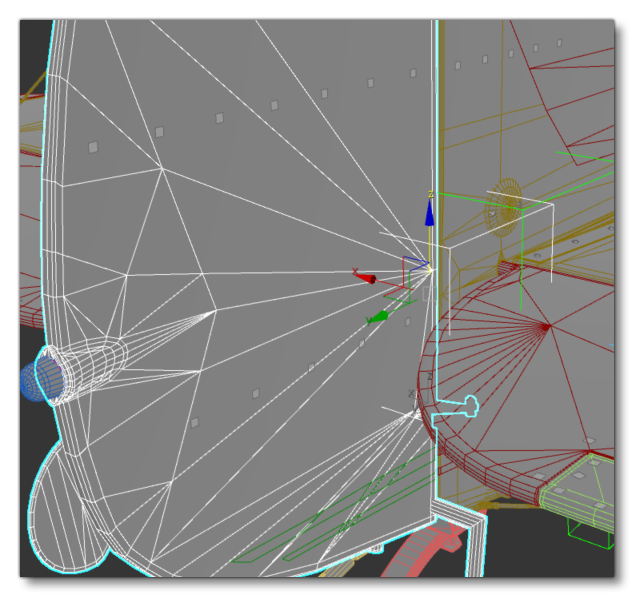
To animate the rudder, you'll need to first create a point (generally using the format Rudder), and then place it on the rotational axis of the rudder mesh. Note that the pivot must be aligned with the rotational axis. With that done you can now link the mesh to the rudder bone with the link tool![]() .
.
The animation of the rudder is done over 4 frames (0 to3):
| Frame | Left Aileron |
|---|---|
| 0 | Neutral position |
| 1 | LEFT (20°-25° angle) |
| 2 | Neutral position |
| 3 | RIGHT (20°-25° angle) |
Mechanisms
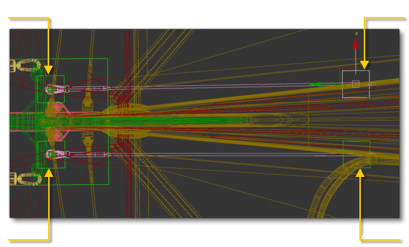
As with other parts, you may have additional mechanisms to add. In the rudder for the example aircraft used here, there are two cables that directly link the rudder to the rudder pedals in the cockpit. To animate these you would need to create two more PLOTs and place them at the intersection between the cable and the rudder, naming them using the standard convention: Rudder_Aux1 and Rudder_Aux2. Since these two must move with the rudder, they need to be linked to the Rudder helper.
Next you would need to create another two PLOTs and place them at the intersection between the cable and the fuselage. These will again be named using the same convention: Rudder_Aux3 and Rudder_Aux4. Since these two shouldn't move with the rudder they should be linked to the helper HIPS.
We also want to ensure that the cables are kept apart from the fuselage when they follow the movement of the rudder, so you'd create a LookAt Constraint between Rudder_Aux1 and Rudder_Aux3, and between Rudder_Aux2 and Rudder_Aux4. After constraint PLOTs, you'd link mesh objects to them: right cable to Rudder_Aux1 and left cable to Rudder_Aux2.
Rear Wheels
We're going to look at a more complex element of the model that is specific to the rudder: having a tail wheel that is linked to the rudder position. To make the wheel follow the rotation of the rudder, we need to constrain the mechanism with the rudder helper.
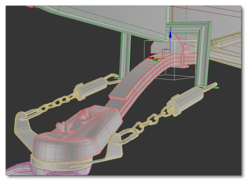
To start with, on the mesh we can see that the axis of rotation of the wheel is fixed to a static element:
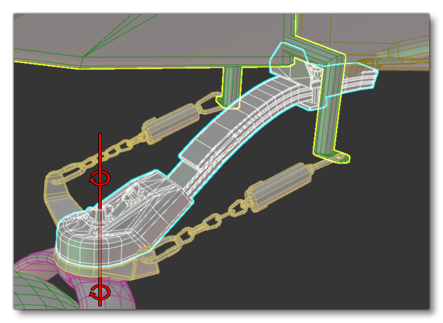
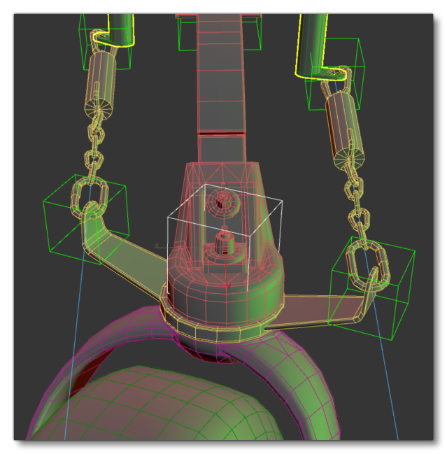
We can also see that the rudder is linked by two chains to the wheel:
So, with this setup, we want the wheel to rotate along with the chains at the same time as when the rudder is moved using the rudder pedals.
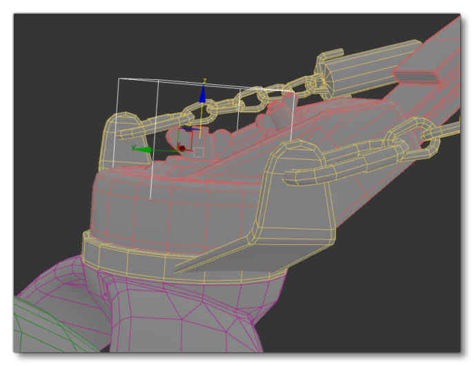
To create this correctly, you'd need a new helper - called something like CenterUpLeg - and this helper will allow us to animate the rear landing gear (just a small movement of deformation when the plane will land). This would be placed at the junction of the landing gear and the fuselage and be linked to the HIPS helper.
Now we need to constrain the rotation of the wheel with the rotation of the Rudder. For that, we create a new PLOT, and name it CenterLeg and then we place it on the rotational axis of the wheel mechanism. The PLOT must be aligned with the axis, not just be placed on it, and be linked to the CenterUpLeg helper.
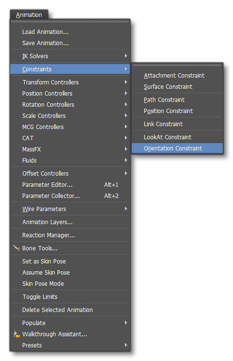
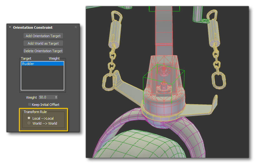
To constrain its rotation, you would go to the Animation menu, select Constraints, then select the Orientation constraint. You can now link the plot with the Rudder helper.
Now you can link objects with the same rotational axis to the PLOT CenterLeg.
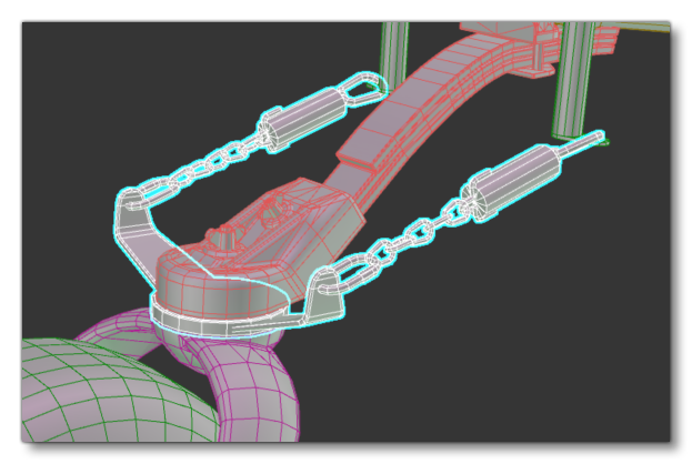
We now need to constrain the chains to follow the rotation. For that, we create two PLOTS (like previous rudder mechanisms) and name them CenterLeg_MasterAux1 and CenterLeg_MasterAux2 and those will be linked with the rudder helper. Next, we'd create two more PLOTs and name them CenterLeg_MasterAux1.1 and CenterLeg_MasterAux2.1 and those will be linked with the CenterLeg Plot.
After that, we create a LookAt constraint between PLOTs: CenterLeg_MasterAux1 with CenterLeg_MasterAux1.1 and CenterLeg_MasterAux2 with CenterLeg_MasterAux2.1. After creating LookAt constraints, we link the left chain to CenterLeg_MasterAux1 and the right chain to CenterLeg_MasterAux2.
 NOTE: You can use Skinning for the chains instead of linking them using PLOTs.