MATERIAL MAPPING
In order to best determine the material breakdown and mapping for the cockpit, there are three elements taken into account.
- Material Type: for example glass cannot share UVs with opaque objects and must be a different ID.
- Texel Density: it may not be possible to have all dials and panels on one sheet and maintain the required texture resolution (more information here: Texel Density)
- Sharing Assets: as you create more aircraft, you'll find that it's easier to share elments (like gauges, glass cockpit displays, seats, etc...) so these will be split into their own IDs.
To give a better idea of how materials should be mapped, there are a couple of examples presented below. Note that the following material texture pages are not in those examples:
- Gauges: All the gauges should be placed on their own material page, and these can include the needles as they will all use an emissive texture.
- Emissives: Any object that is not a decal but requires an emissive should be on this page. This will include inner lights, misted light glass (this does not need to be on the glass page as it doesn't have alpha) and any dials that glow entirely.
Example 1:
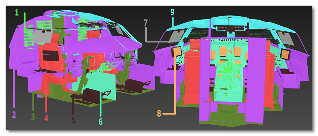
In this example the materials are broken down and mapped as follows:
| Material | Area Used | Texture Size And Notes |
|---|---|---|
| 1 | Dials and switches (page 1) | 2K |
| 2 | Main body page | 2K |
| 3 | Yoke and carpet |
2K These will require a high resolution to attain the detail necessary (high res micro scratches on yoke handle, and normal map on carpet). The other elements can be moved to another ID if necessary. |
| 4 | Seats |
2K Left and right can be mirrored instances. |
| 5 | Dials and switches (page 2) |
2K As page 1 but includes pedals to fill out the texture sheet to the same texel density. |
| 6 | The centre console | 2K |
| 7 | Glass shader |
2K This will likely be less when rendered in the simulation. |
| 8 | Screens | No texture required, but they need to be mapped correctly with the correct aspect ratio of the actual screen. |
| 9 | Ceiling |
2K This will likely be less when rendered in the simulation. |
| 10 (Not shown) |
Decals |
2K Make good use of the texture sheet reusing labels and words where possible. See here for more information: Decals And Detail Maps |
Example 2:
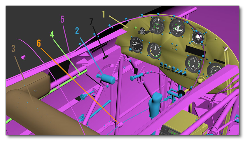
In this example the materials are broken down and mapped as follows:
| Material | Area Used | Texture Size And Notes |
|---|---|---|
| 1 | Main interior | 2K |
| 2 | Inputs | 2K Includes yoke and pedals. |
| 3 | Seats |
2K |
| 4 | Interior Glass |
2K |
| 5 | Secondary Interior |
2K |
| 6 | Alpha Rivets | 2K |
| 7 | Decal Text |
2K |
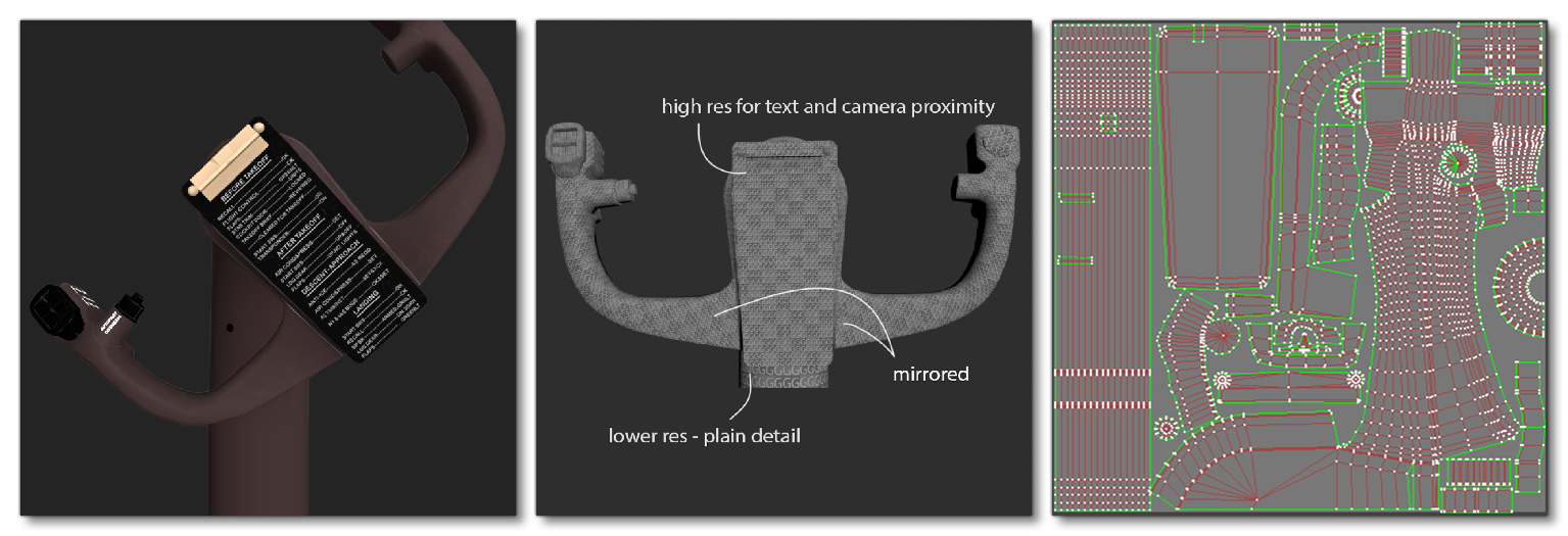
Sub-Object Breakdown
Specific components should be broken up as sub-objects from the rest of the cockpit in order to reduce the total size of the texture atlas and also to allow for dynamic lodding. When doing this you must ensure that you map them efficiently in order to get the best resolution where you need it most. The following images show a steering yoke as an example of how this can best be achieved, as it is entirely seperate from the rest of the cockpit, both in mesh and also in texture ID. Also note that in this example the parts that can be mirrored are mirrored and the parts that can be reduced in resolution have been.