POLYGON OBJECTS
A Polygon object is an object element used to define an N sided area (minimum 3 sides) that you can create to define an arbitrary area in the scene to manipulate in some way. The properties that you assign to the polygon will allow you to do some of the following:
- flatten the terrain
- exclude auto-generated buildings
- force or exclude vegetation
- change vegetation type
- specify airport zones (changes the type of auto-generated buildings)
- apply a material to the ground
- add or remove water
When you select this object type the Objects window will not show any different object elements as currently there is only one type of polygon and what it does is defined through its Properties:

When you select a polygon object and click Add, the cursor will have a red cross-hair attached to it, and if you then hold down Ctrl and use the Left Mouse Button you can start to place points on the world to outline the shape.
IMPORTANT! You can have a maximum of 13107 (vertices) in a polygon object. Any more than that will mean the polygon will not be displayed by the simulation, although we recommend that you never even get close to this upper limit for performance reasons, and only use the absolute minimum of points necessary at all times.
When you are happy with the area you have delineated, you can press Enter to "fix" the shape, which will now look like this in the world:

The polygon will have a Gizmo in its center and this can be used to change the position/rotation/scale of the polygon. Note that polygons can be convex or concave, so you can define just about any area, although the edges of the polygonal area should never cross, as this will lead to errors when rendering or performing the actions required of the polygon. If you wish to remove the polygon object from the world, you can select it and then press the Delete key.
If you want to change the area that the polygon covers after you have created it, you can click the Left Mouse Button on any point to set the gizmo to that point. This point can then be translated to a new position using the gizmo or by inputting new values in the gizmo window, updating the area of the polygon as you do.
Polygon objects also have specific commands available from the Right Mouse Button menu (see here for information on the general RMB options - Scene RMB Menu):

- Add Point - When you right click on an edge of the polygon and select this option, a new point (vertex) will be added to the edge at the position that was clicked.
- Remove Point - Right clicking and selecting this option on any point of the polygon will remove that point.
- Split Edge - When you right click on an edge of the polygon and select this option, a new point will be added to the center point of the edge.
- Resume Editing - Selecting this option will put you back into the edition mode, the same as when you first added the polygon object to the scene. There will be a red cross-hair and you can add points to the polygon using
Ctrl+ Left Mouse Button, and then finalise usingEnter. - Reset Points Altitude - From this sub-menu you have two options that are used to reset the altitude of all points on the path:
- At Ground Level - When this is selected, each point will be snapped to the ground altitude at the point position.
- At Center Level - When this is selected, the simulation will calculate the altitude center point (as a mean of the altitudes of all points in the polygon), and set all points to this altitude, essentially "flattening" the polygon.
IMPORTANT! If you load a previously created scenery project into DevMode, it is possible that you will be asked if you want to convert terraforming to the "new" system. This is a permanent change and cannot be undone, so if you are happy with the way your terraforming looks, you should select Cancel. For more information, please see here: Old Terraforming Method 
Polygon objects come in two "types", either regular or water and they both have different Properties which can be edited. The sections below give descriptions of these properties based on the type selected.
Regular Polygon

-
Name
This is the name of the element as defined from its properties. For example if you have selected the Airport Area option, the name would become "Polygon (Airport Texture)".
-
Display Name
This is the name of the element as it will be displayed in the The Scenery Contents List. This can be edited and is helpful for identifying elements when you have a lot of items in the content list.
-
Unique ID
This shows the GUID-formatted Instance ID unique to the specific instance of the polygon object placed within the simulation. If you need the GUID for this instance of the object then you can use the
Copy...button to add the GUID into the clipboard.
Excludes

-
Exclude All Buildings
This is a convenience option which will check/uncheck all the other exclude building options in a single click.
NOTE: These data-sets can overlap, so you may see different buildings in the same locations if you exclude one or the other of OSM or Detected buildings, and so will need to exclude both kinds to clear the area.
-
Exclude TIN
The TIN data is data streamed from Bing Maps, which may include buildings as well as other things.
-
Exclude Detected Buildings
These are buildings created algorithmically from the aerial image data.
-
Exclude OSM Buildings
These are buildings created from the data supplied by Open Street Maps.
-
Exclude MS Buildings
These are buildings generated from open-source data for North America that comes from Microsoft.
-
Exclude Secondary Heightmaps
Secondary heightmaps are those which add more "ruggedness" to the ground, and so enabling this option will exclude any those heightmaps within the defined polygon and create a much flatter area of terrain. Note that while this will help flatten the terrain, there will still be some surface heightmap detail applied from the primary heightmap.
-
Exclude Roads
Enabling this option will exclude any roads and traffic that have been generated within the bounds of the polygon. Note that traffic will generally instantly stop spawning but roads may still be visible or require some time to update correctly while being previewed in the scenery editor.
-
Exclude Street Lights
Enabling this option will exclude any streetlights that have been generated within the bounds of the polygon.
-
Exclude Feature Points
Enabling this option will have the polygon exclude exclude feature points. Feature points are generated from OSM - for example, windmill, wind turbine, com masts, etc... - and these will be excluded within the polygon, along with any lights that are associated with them.
Buildings

-
Force Buildings On Tin
This can be used when you have excluded TIN data, but want to still have TIN generated buildings present.
-
Force Detected Buildings
This option can be used to force the rendering of detected buildings for an area.
Terraforming

-
Enable
When this option is checked, the polygon shape can be used to terraform the terrain based on the form of the polygon and its altitude, as set through the translate Gizmo.
-
Falloff Distance
This sets the distance around the polygon which will be "feathered", smoothing the difference in altitude between the polygon terraformer and the surrounding terrain. This is shown in the scene as a dashed line, and the value is in meters.

-
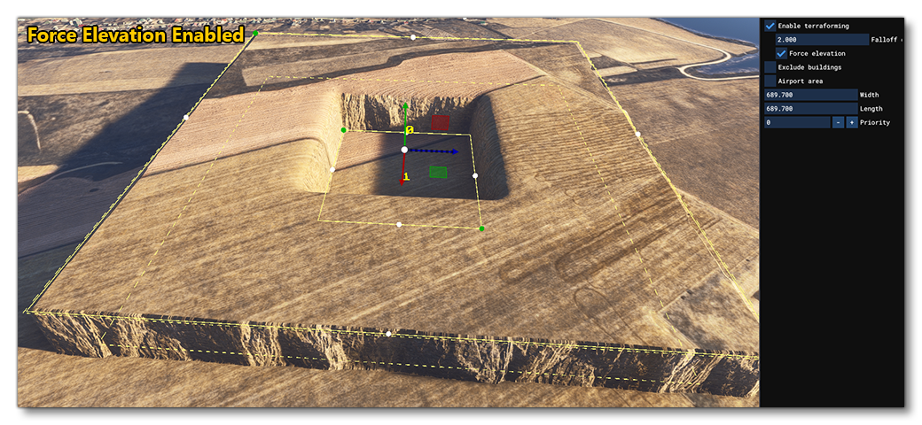
Force Elevation
When enabled, this option will force the ground to be at the same elevation as the terraformer, creating a perfectly flat surface. This means, however, that you can't overlap terraformers without having severe discontinuity in the terrain (the Priority setting of the polygon is used to define which terraformer is used). When this option is disabled you can more easily mix terraformers, as the falloff can sculpt any other terraformers that overlap. You can mouse over the image below to see examples of this option enabled and disabled (note that image shows the Rectangle Object but the effect is the same for polygons):
-

Material

This section permits you to define the type of surface material that will be used by the area in the polygon. Clicking the ... button will open The Material Editor where you will see a list of the available materials. You would then select the one you want from this list, click on it then drag it onto the ... button to apply it to the polygon. The button name will then change to name of the material that you have just applied. To return to the default material, click the x button. Note that this option will have no effect if the polygon is set to Vegetation.IMPORTANT! When being rendered, polygon elements are baked into the terrain textures. This helps reduce the polycount and permits the element to be terraformed. However, it also means that the texture quality won't be any greater than the resolution of the terrain textures themselves. In general, this resolution is around 4mm/pixel at the equator, with the best/highest resolution terrain textures reserved for higher LODs so we have a better quality for airports. For users, they will experience the best resolution possible setting the "Terrain level of detail" option to its maximum value.
-
Stretch UV
This will stretch the material texture UVs so that the material texture fills the entire polygon width/height without tiling.
-
Tiling
This sets the tiling scale for the texture used by the material. Note that this option will not be available if the Stretch UV option is checked.
-
Texture Offset U / V
This sets the U/V offset for the material texture.
-
Rotation
This sets the angle at which the material texture will be rendered.
-
Falloff
This sets the distance around the polygon in which the material will be "feathered" to smooth the transition between the polygon material and the terrain.
-
Opacity
This setting is for changing the transparency of the material.
-
Ground Merging
When this is checked, the terrain textures under the polygon will be merged with the material texture, subtly changing it's colouring and patterning.
-
Coloration
This permits you to add a colored "tint" to the material. Setting the RGB values to (0, 0, 0) will remove all tinting.
Note that if you have enabled the Vegetation Mask Override or option then no material will be shown for the polygon until that option is disabled again.
Vegetation Override

-
Enable Vegetation Mask Override
When this option is enabled, the polygon will be filled with vegetation. By default, the vegetation used will be in accordance with the biome for the zone that you are creating scenery for, but you can use the biome override option to change this to anything supported, even custom vegetation. Note that when this option is enabled, any you have selected will no longer be shown.

-
Exclude
When this is checked, the polygon will exclude any vegetation from being spawned in the area. Enabling this will disable the other options related to vegetation as they are no longer relevant.
-
Scale
This sets the scale of the vegetation within the polygon.
-
Density
This sets the density of vegetation within the polygon. Note that if you set this too high for the current graphics settings then a warning will be shown. Getting this warning means that you will not be seeing the actual results of the density setting as the vegetation has been "capped", and you should either lower the density or edit the "Trees" setting in the simulation graphics options.
-
Falloff Distance
This sets the distance around the polygon in which the vegetation will be "feathered" between the edge and the surrounding terrain. This is shown in the scene as a dashed line.
-
Biome Override
Clicking the
Select...button permits you to select a different biome to be used for the vegetation within the polygon area. Note that changing this option will affect all the vegetation in the polygon, whether you have the Vegetation option checked or not. To return to the default biome data, click theClear Selectionbutton from the drop-down list.
Rocks Override

-
Enable Override
When this option is enabled, the polygon will be filled with rocks. By default, the rocks used will be in accordance with the geome for the zone that you are creating scenery for, but you can use the geome override option to change this to anything supported by the game, even custom rocks. Enabling this will also show additional sliders to control how the rocks are rendered.

-
Exclude
When this is checked, the polygon will exclude any vegetation from being spawned in the area. Enabling this will disable the other options related to vegetation as they are no longer relevant.
-
Scale
This sets the scale of the rocks within the polygon.
-
Density
This sets the density of the rocks within the polygon.
-
Falloff Distance
This sets the distance around the polygon in which the rocks will be "feathered" between the edge and the surrounding terrain. This is shown in the scene as a dashed line.
-
Geome Override
Clicking theSelect...button permits you to select a different geome to be used for the rocks within the polygon area. To return to the default geome data, click theClear Selectionbutton from the drop-down list.
Airport Area
This option tells the simulation that the polygon area is part of an airport. Selecting this option will affect how some of the buildings within the polygon are rendered in the world (including forcing the display of any TIN buildings, regardless of whether Force Buildings On Tin is unchecked or not), and also open a further option to set the approximate size of the airport:

This option will exclude any type of fauna from the area as well as affect the size and type of buildings that may be auto-generated in the area, including certain airport models like ATC Towers.
Extra Properties

-
Subject Photo GUID
This option is used to assign a unique GUID string to the polygon. This can then be used in the World Photographer missions to identify an area to be photographed as part of the mission.
NOTE: Currently this kind of mission cannot be created, but the documentation for these missions will be added in a future SDK update, when it is available in the simulation for developers.
-
Priority
This option sets the render priority for the polygon. The default render priority is 0, which for most cases is fine. However, if you have overlapping polygons and want one to render over another one, then you will need to change this value clicking the
+or-buttons to raise or lower the priority value. Higher priority values will render over lower priorities, for example, a polygon with priority 1 will render over one with priority 0, which in turn will render over one with priority -1. Note that the engine cannot guarantee the render order for polygons with the same priority, so if you need something to always render over or under something else, you need to set this value. If the polygon is flagged as terraforming then the priority value will be rendered in the world view to make debugging easier. Finally, this option will only affect the following polygon features:-
Material draw order
-
Vegetation brightness
-
Rock generation vs rock exclusion
-
Water Polygon

Selecting this option tells the simulation that the polygon is defining an area of water. Here you can choose the type of water that is to be rendered within the polygon, or you can choose the Exclude option to remove any water from within the area.
NOTE: when Exclude is ticked, the water polygon excludes only the type of water that is selected. In the image further down the page, the bigger polygon is OCEAN, so the central exclusion polygon only works if it is also of type OCEAN.
The image below shows a water polygon in a scene:

If you wish to exclude part of this polygon, for example to create an island, you can create a new polygon object, set it to water - ensuring that the type is the same as the base polygon, so if the main polygon is Ocean the exclude polygon must be Ocean too - and then select Exclude:

You can see in the image above that the edges of the water are "feathered" with the land to create a smooth transition. This is because water polygons create a distance field on the water-side of the polygon boundary to create the shoreline. Also note that water polygons will work additively when multiple overlapping polygons are used together. A single water polygon increments the internal "water" value by 1, while a water polygon with Exclude decrements the internal "water" value by 1. The distance field will be applied based on this value, so an internal "water" value greater than 0 will mean that water is rendered while a value of 0 or less will mean that water is not rendered.

IMPORTANT! Polygons of the same water type do not merge! If you have overlapping polygons of the same type they will cancel each other out and create what appears to be an exclusion area, only without the correct distance field feathering. So, avoid overlapping polygons unless you are creating an exclusion area or they are different types.