HYDRAULIC SYSTEM EXAMPLES
It can be complex to set up a Modular Hydraulics System, and so on this page we provide two examples to help you. These samples cover a simple aircraft (like the DA62) and a complex aircraft (like the Boeing 737), and provides both a visual schematic for the systems being created, and the resulting CFG settings.
Simple Aircraft
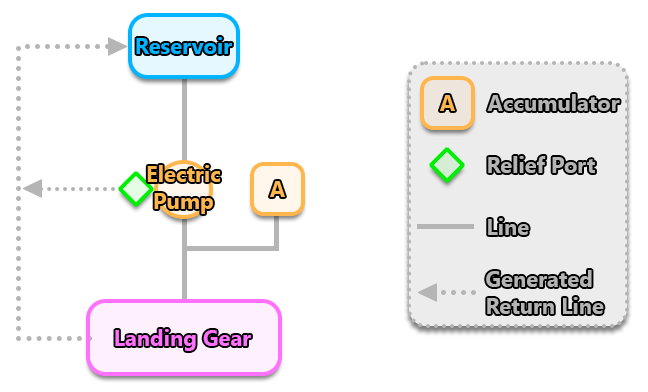
The hydraulics system for small aircraft is a very simple one, as it only has a single actuator for the landing gear. For this actuator to work it requires the actuator itself as well as a single reservoir and an automatic electric pump provide the actuator with pressurized fluid, along with an accumulator (which allows the pilot to extend the landing gear even if the pump fails). The image below shows the schematic for the DA62 hydraulic system:

The CFG file contents for the components in this system would look like this:
[HYDRAULICS_SYSTEM_EX1]
Version = 1
Reservoir.1 = Name:Tank #Maxcapacity:10 #WearAndTearCollision:GlobalDamage
Pump.1 = Name:ElectricPump #Type:Electric #Normalpressure:2000 #Nominaldisplacement:600 #Circuit:HydraulicPump #Mode:Auto #WearAndTearCollision:GlobalDamage
Accumulator.1 = Name:Accumulator #Normalpressure:2000 #Initialpressure:1700 #Capacity:500 #WearAndTearCollision:GlobalDamage
Actuator.1 = Name:LandingGear #Fluidvolume:300 #Minimalpressure:1300 #Type:LandingGear #WearAndTearCollision:GlobalDamage
Line.1 = Name:TankToPump #Inputs:Tank #Outputs:ElectricPump #WearAndTearCollision:GlobalDamage
Line.2 = Name:PumpToLdgGear #Inputs:ElectricPump #Outputs:LandingGear #Accumulator:Accumulator #WearAndTearCollision:GlobalDamage
In this simple system, the accumulator can hold 500ml of hydraulic fluid at pump pressure, and the actuator consumes 100ml/s. This means that the accumulator can sustain the actuator for 5 seconds, but as it depletes its pressure will decrease towards its pre-charged pressure, and so it may fall below the minimal pressure of the actuator if not set correctly.
Complex Aircraft
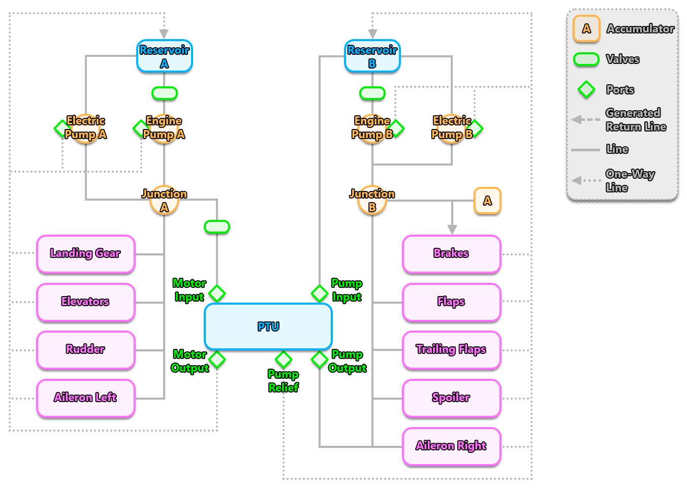
The hydraulics system of a complex aircraft - like an airliner - is a more complex setup than the one used by the simple aircraft shown above. It has two separate hydraulics systems which are connected via a non-reversible PTU. The PTU itself is the most complex of the hydraulic components as it has multiple ports to deal with the various input and output lines. Notice that this one does not use the Motor Relief port. If it was reversible then this would be required as well. The way this system is setup means that the "A" system can provide the "B" system with hydraulic power if necessary. It is also worth noting that the number of hydraulic pumps has been doubled for the complex aircraft, as each system has an electric pump and an engine driven pump. This provides redundancy to the system, so that having a failure on any one of the pumps will not cause a catastrophic system failure.

The CFG file contents for the components in this system would look like this:
[HYDRAULICS_SYSTEM_EX1]
Version = 1
Reservoir.1 = Name:TANKA #MaxCapacity:10
Reservoir.2 = Name:TANKB #MaxCapacity:10
Valve.1 = Name:ValveSO_A #Type:ShutOff #Circuit:C_HYDRAULIC
Valve.2 = Name:ValveSO_B #Type:ShutOff #Circuit:C_HYDRAULIC
Valve.3 = Name:ValvePTU #Type:ShutOff #Index:3
Pump.1 = Name:Pump_ENG_1 #NormalPressure:3000 #NominalDisplacement:2400 #Type:EngineDriven #Index:1
Pump.2 = Name:Pump_ENG_2 #NormalPressure:3000 #NominalDisplacement:2400 #Type:EngineDriven #Index:2
Pump.3 = Name:Pump_ELEC_1 #NormalPressure:3000 #NominalDisplacement:800 #Type:Electric #Circuit:C_Hyd_PUMP_1
Pump.4 = Name:Pump_ELEC_2 #NormalPressure:3000 #NominalDisplacement:800 #Type:Electric #Circuit:C_Hyd_PUMP_2
Accumulator.1 = Name:AccumulatorBrakes #NormalPressure:3000 #InitialPressure:1080 #Capacity:3
Actuator.1 = Name:Rudder #MinimalPressure:1500 #FluidVolume:400 #Type:Rudder
Actuator.2 = Name:Flaps #MinimalPressure:1500 #FluidVolume:400 #Type:Flaps#Index:1
Actuator.3 = Name:Brakes #MinimalPressure:1000 #FluidVolume:400 #Type:Brakes
Actuator.4 = Name:LandingGear #MinimalPressure:1500 #FluidVolume:400 #Type:LandingGear
Actuator.5 = Name:Spoilers #MinimalPressure:1500 #FluidVolume:400 #Type:Spoilers
Actuator.6 = Name:Elevator #MinimalPressure:1500 #FluidVolume:400 #Type:Elevator
Actuator.7 = Name:AileronsL #MinimalPressure:1500 #FluidVolume:400 #Type:LeftAilerons
Actuator.8 = Name:AileronsR #MinimalPressure:1500 #FluidVolume:400 #Type:RightAilerons
Actuator.9 = Name:FlapsTrail #MinimalPressure:1500 #FluidVolume:400 #Type:Flap #Index:2
Junction.1 = Name:JunctionA
Junction.2 = Name:JunctionB
PTU.1 = Name:PTU #NormalPressure:3000 #NominalDisplacement:1200
Line.1 = Name:TankAToPumpEng #Inputs:TANKA #Outputs:Pump_ENG_1 #Valves:ValveSO_A
Line.2 = Name:TankAToPumpElec #Inputs:TANKA#Outputs:Pump_ELEC_1
Line.3 = Name:PumpsToJunctionA #Inputs:Pump_ENG_1,Pump_ELEC_1 #Outputs:JunctionA
Line.4 = Name:JunctionAToActuators #Inputs:JunctionA #Outputs:LandingGear,Elevator,Rudder,AileronsL
Line.5 = Name:JunctionAToPTUMotor #Inputs:JunctionA #Outputs:PTU.MotorInput #Valves:ValvePTU
Line.6 = Name:TankBToPumpEng #Inputs:TankB #Outputs:Pump_ENG_2 #Valves:ValveSO_B
Line.7 = Name:TankBToPumpElec_PTU #Inputs:TANKB #Outputs:Pump_ELEC_2,PTU.PumpInput
Line.8 = Name:PumpsToPTUActuatorsB #Inputs:PTU.PumpOutput, Pump_ENG_2, Pump_ELEC_2 #Outputs:Flaps, Spoilers, AileronsR, FlapsTrail, JunctionB
Line.9 = Name:JunctionBToBrakes #Inputs:JunctionB #Outputs:Brakes #Accumulator:AccumulatorBrakes #NonReturn