PNEUMATIC SYSTEM EXAMPLES
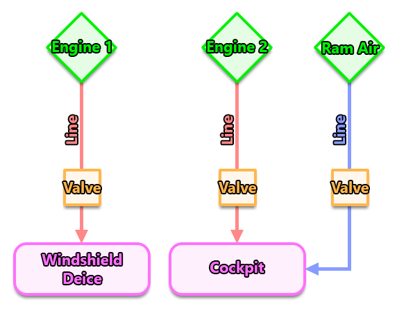
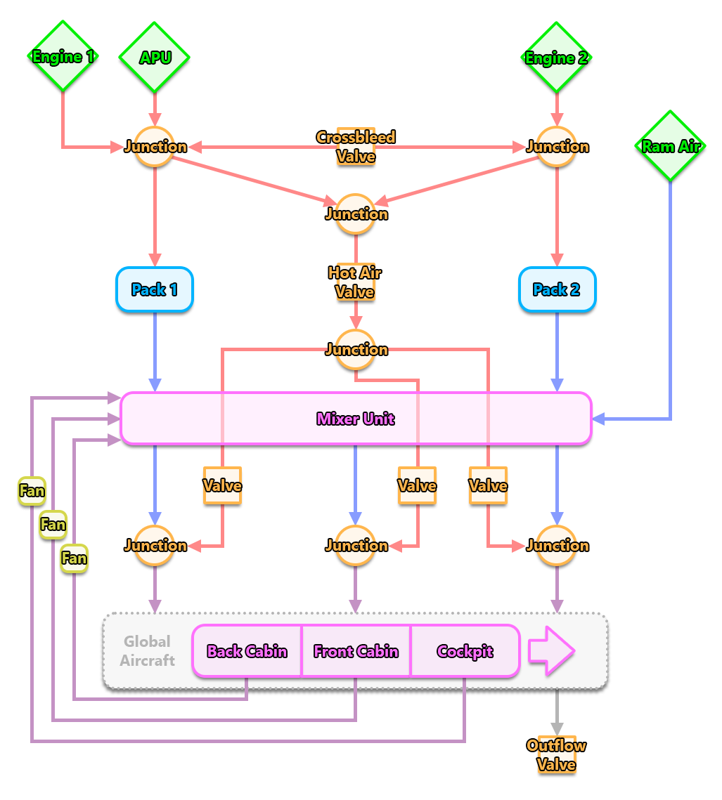
It can be complex to set up a Modular Pneumatic System, and so on this page we provide two examples to help you. These samples cover a simple small aircraft (like the DA62) and a complex large aircraft (like the Boeing 737), and provides both a visual schematic for the systems being created, and the resulting CFG settings.
Small Aircraft
The pneumatic system of small aircraft is a very simple one with one pneumatic engine powering windshield deicing and the other pneumatic engine powering the cockpit. The cockpit also has a link to a ram air entry. All of the lines for this system are controlled by valves, and there are no other components used. The image below shows an example schematic for a small aircraft (like the DA62) pneumatic system:

The CFG file contents for the components in this system would look like this:
[PNEUMATIC_SYSTEM_EX1]
Version = 1
Engine.1 = Name:LeftEngine #Index:1 #BleedTemperaturesCurve:1 #Outputflow:0.2
Engine.2 = Name:RightEngine #Index:2 #BleedTemperaturesCurve:1 #Outputflow:0.2
Curve.1 = 0:30, 100:60
RamAir.1 = Name:RamAir #Surface:0.1
Outlet.1 = Name:WindshieldDeice #Type:WindshieldDeice
Area.1 = Name:Cockpit #Volume:10 #AmbientBleedStaticFlow:0.02
Valve.1 = Name:LeftEngineHotAirValve #Circuit:1
Valve.2 = Name:RightEngineHotAirValve #Circuit:2
Valve.3 = Name:RamAirValve #Circuit:3
Line.1 = Name:LeftEngineToWindShieldDeice #Source:LeftEngine #Destination:WindshieldDeice #Valves:LeftEngineHotAirValve #WearAndTearCollision:GlobalDamage
Line.2 = Name:RightEngineToCockpit #Source:RightEngine #Destination:Cockpit #Valves:RightEngineHotAirValve
Line.3 = Name:RamAirToCockpit #Source:RamAir #Destination:Cockpit #Valves:RamAirValve
Large AIrliner
Most large airliners need a lot of components as they has to manage pressure using at least two engines and an APU. We see on the schematic below, that there are lines connecting an engine to its corresponding pack, but they are also connected to each other via the crossbleed valve (a ram air entry is also possible, directly in the mixer unit). The bleed air that enters the packs is cooled and sent to the mixer unit, and from there it will be pushed into the corresponding areas. At the same level as the packs, the hot air valve receives the bleed air coming from each engine and lets it go through to the valves regulating the hot air in the corresponding areas. After those valves, the hot air is mixed (if needed) with the cold air coming from the mixer unit and arrives in the areas where it will affect the temperature and the pressure of the aircraft. Note that areas send back some of the air to the mixer unit, completing the air loop. The outflow valve at the bottom manages the pressure in the aircraft and opens accordingly.

The CFG file contents for the components in this system would look something like this:
[PNEUMATIC_SYSTEM_EX1]
Version = 1
AreasMinTemperature = 18.0
AreasMaxTemperature = 30.0
MaxDifferencialPressure = 8.9
AreasMaxTemperatureInput = 70.0
APU.1 = Name:APU #BleedTemperaturesCurve:1 #OutputFlow:3.0
RamAir.1 = Name:RamAir #Surface:0.05
Engine.1 = Name:LeftEngine #Index:1 #BleedTemperaturesCurve:2 #OutputFlow:3.0
Engine.2 = Name:RightEngine #Index:2 #BleedTemperaturesCurve:2 #OutputFlow:3.0
Curve.1 = 0:200, 100:220
Curve.2 = 0:200, 100:250
Pack.1 = Name:LeftPack #Circuit:1 #DefaultTemperatureOutput:24 #PackFlowLow:0.8 #PackFlowHigh:1.2 #MinTemperatureOutput:8 #MaxTemperatureOutput:50 #TypicalFlow:3.0
Pack.2 = Name:RightPack #Circuit:2 #DefaultTemperatureOutput:18 #PackFlowLow:0.8 #PackFlowHigh:1.2 #MinTemperatureOutput:8 #MaxTemperatureOutput:50 #TypicalFlow:3.0
MixerUnit.1 = Name:MixerUnit
Area.1 = Name:Cockpit #Volume:13 #AmbientBleedStaticFlow:0.02
Area.2 = Name:FrontCabin #Volume:250 #Bleed:1, 0.2:3, 0.5 #AmbientBleedStaticFlow:0.02
Area.3 = Name:BackCabin #Volume:250 #AmbientBleedStaticFlow:0.02
Outlet.1 = Name:WingsDeice #Type:WingDeice
Valve.1 = Name:OutflowValve #Circuit:1 #Type:Outflow #OpeningTime:3.0
Valve.2 = Name:CrossbleedValve #Circuit:2 #Type:Crossbleed #OpeningTime:3.0
Valve.3 = Name:HotAirValve #Circuit:3 #Type:HotAir
Valve.4 = Name:CockpitHotAirValve #Circuit:4 #ManagedArea:Cockpit
Valve.5 = Name:FrontCabinHotAirValve #Circuit:5 #ManagedArea:FrontCabin
Valve.6 = Name:BackCabinHotAirValve #Circuit:6 #ManagedArea:BackCabin
Valve.7 = Name:RamAirValve
Junction.1 = Name:LeftJunction #InputOnlyLines:APUToLeftJunction #OutputOnlyLines:LeftJunctionToEnginesHotAirJunction, LeftJunctionToLeftPack
Junction.2 = Name:RightJunction #OutputOnlyLines:RightJunctionToEnginesHotAirJunction, RightJunctionToRightPack
Junction.3 = Name:EnginesHotAirJunction #InputOnlyLines:RightJunctionToEnginesHotAirJunction, LeftJunctionToEnginesHotAirJunction #OutputOnlyLines:EnginesHotAirJunctionToAreasHotAirJunction
Junction.4 = Name:AreasHotAirJunction #InputOnlyLines:EnginesHotAirJunctionToAreasHotAirJunction #OutputOnlyLines:AreasHotAirJunctionToCockpitJunction, AreasHotAirJunctionToFrontCabinJunction, AreasHotAirJunctionToBackCabinJunction
Junction.5 = Name:CockpitJunction #InputOnlyLines:MixerUnitToCockpitJunction, AreasHotAirJunctionToCockpitJunction #OutputOnlyLines:CockpitJunctionToCockpit
Junction.6 = Name:FrontCabinJunction #InputOnlyLines:MixerUnitToFrontCabinJunction, AreasHotAirJunctionToFrontCabinJunction #OutputOnlyLines:FrontCabinJunctionToFrontCabin
Junction.7 = Name:BackCabinJunction #InputOnlyLines:MixerUnitToBackCabinJunction, AreasHotAirJunctionToBackCabinJunction #OutputOnlyLines:BackCabinJunctionToBackCabin
Junction.8 = Name:OutflowJunction #InputOnlyLines:CockpitAreaToOutflowJunction, FrontCabinAreaToOutflowJunction, BackCabinToOutflowJunction #OutputOnlyLines:OutflowJunctionToOutflowValve
Line.1 = Name:APUToLeftJunction #Source:APU #Destination:LeftJunction
Line.2 = Name:LeftEngineToLeftJunction #Source:LeftEngine #Destination:LeftJunction
Line.3 = Name:RightEngineToRightJunction #Source:RightEngine #Destination:RightJunction
Line.4 = Name:LeftJunctionToRightJunction #Source:LeftJunction #Destination:RightJunction #Valves:CrossbleedValve
Line.5 = Name:LeftJunctionToEnginesHotAirJunction #Source:LeftJunction #Destination:EnginesHotAirJunction
Line.6 = Name:LeftJunctionToLeftPack #Source:LeftJunction #Destination:LeftPack
Line.7 = Name:RightJunctionToEnginesHotAirJunction #Source:RightJunction #Destination:EnginesHotAirJunction
Line.8 = Name:RightJunctionToRightPack #Source:RightJunction #Destination:RightPack
Line.9 = Name:EnginesHotAirJunctionToAreasHotAirJunction #Source:EnginesHotAirJunction #Destination:AreasHotAirJunction #Valves:HotAirValve
Line.10 = Name:LeftPackToMixerUnit #Source:LeftPack #Destination:MixerUnit
Line.11 = Name:RightPackToMixerUnit #Source:RightPack #Destination:MixerUnit
Line.12 = Name:MixerUnitToCockpitJunction #Source:MixerUnit #Destination:CockpitJunction
Line.13 = Name:MixerUnitToFrontCabinJunction #Source:MixerUnit #Destination:FrontCabinJunction
Line.14 = Name:MixerUnitToBackCabinJunction #Source:MixerUnit #Destination:BackCabinJunction
Line.15 = Name:AreasHotAirJunctionToCockpitJunction #Source:AreasHotAirJunction #Destination:CockpitJunction #Valves:CockpitHotAirValve
Line.16 = Name:AreasHotAirJunctionToFrontCabinJunction #Source:AreasHotAirJunction #Destination:FrontCabinJunction #Valves:FrontCabinHotAirValve
Line.17 = Name:AreasHotAirJunctionToBackCabinJunction #Source:AreasHotAirJunction #Destination:BackCabinJunction #Valves:BackCabinHotAirValve
Line.18 = Name:CockpitJunctionToCockpit #Source:CockpitJunction #Destination:Cockpit
Line.19 = Name:FrontCabinJunctionToFrontCabin #Source:FrontCabinJunction #Destination:FrontCabin
Line.20 = Name:BackCabinJunctionToBackCabin #Source:BackCabinJunction #Destination:BackCabin
Line.21 = Name:CockpitToMixerUnit #Source:Cockpit #Destination:MixerUnit
Line.22 = Name:FrontCabinToMixerUnit #Source:FrontCabin #Destination:MixerUnit
Line.23 = Name:BackCabinToMixerUnit #Source:BackCabin #Destination:MixerUnit
Line.24 = Name:LeftJunctionToWingsDeice #Source:LeftJunction #Destination:WingsDeice
Line.25 = Name:CockpitAreaToOutflowJunction #Source:Cockpit #Destination:OutflowJunction
Line.26 = Name:FrontCabinAreaToOutflowJunction #Source:FrontCabin #Destination:OutflowJunction
Line.27 = Name:BackCabinToOutflowJunction #Source:BackCabin #Destination:OutflowJunction
Line.28 = Name:OutflowJunctionToOutflowValve #Source:OutflowJunction #Destination:OutflowValve
Line.29 = Name:RamAirToCockpit #Source:RamAir #Destination:Cockpit #Valves:RamAirValve
No Packs
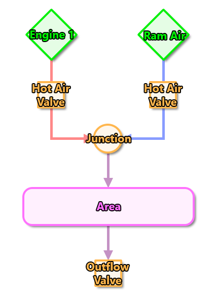
This example is not from any specific aircraft, but is meant to illustrate a very simple setup that does not use any packs to regulate temperature or pressure:

The CFG file contents for the components in this system would look like this:
Version = Latest
Curve.1 = 0:150, 100:200
RamAir.1 = Name:RamAir #Surface:0.05
Engine.1 = Name:Engine #BleedTemperaturesCurve:1 #OutputFlow:1.0
Valve.1 = Name:HeatingValve #Circuit:1 #ManagedArea:Cabin ; Automatic Valve managing Heating
Valve.2 = Name:ColdAirValve #Circuit:2          ; Manual valve to add cold air
Valve.3 = Name:OutflowValve #Circuit:3 #Type:Outflow
Junction.1 = Name:CabinJunction
Area.1 = Name:Cabin #Volume:15
Line.1 = Name:EngineToJunction #Source:Engine #Destination:CabinJunction #Valves:HeatingValve
Line.2 = Name:RamAirToJunction #Source:RamAir #Destination:CabinJunction #Valves:ColdAirValve
Line.3 = Name:JunctionToCabin #Source:CabinJunction #Destination:Cabin
Line.4 = Name:CabinToOutflow #Source:Cabin #Destination:OutflowValve