AIRCRAFT.XML AND MODEL.CFG
Assuming that you've exported your interior and exterior models into the appropriate folders within the aircraft package, the next step is to link the files to the aircraft you are creating within the simulation. For that you need to set up the model.cfg file and also create (at least) two XML files for the aircraft - one for the interior and one for the exterior. On this page we'll go through the basics of how to make these files.
model.cfg
This file is very simple to setup and is what is used to tell the simulation what XML files will be used to define the different models used for the different LODS, as well as to define their animations and behaviors. When you first created the aircraft project, the model.cfg file will have been created for you in the model folder (where you should have saved the glTF files), and will look like this:

The first thing you need to do here is setup the [models] section to point to two files which will defined the aircraft model behaviors. These files don't exist yet - we'll create them later - but we can still give their names here. These files usually follow the same format:
<aircraft_name>.xml
<aircraft_name>_interior.xml
EG:
da62.xml
da62_interior.xml
So for a basic aircraft, the model.cfg file will now look like this:
[models]
exterior=myaircraftname_aircraft.xml
interior=myaircraftname_aircraft_interior.xml
The next thing you would need to add to this file is the [model.options] section. This section has some parameters that are used to tell the simulation how the interior and exterior models should interact, and a general "rule of thumb" for these options is that if you have an interior model, they should all be set to true, and if you don't then they should all be set to false. So, at the top of the file, before the [models] section, you would add the following:
[model.options]
withExterior_showInterior=true
withExterior_showInterior_hideFirstLod=true
withInterior_forceFirstLod=true
withInterior_showExterior=true
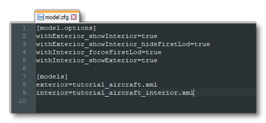
AFter this the whole file should look something like this:

At this point you want to save the file to the "models" folder for the aircraft, which should have a path similar to the following:
ROOT\<PackageName>\PackageSources\SimObjects\Airplanes\<AircraftName>\model\model.cfg
Aircraft XML
Having created the CFG file and referenced the interior and exterior XML files, the next logical step is to create those files. The XML files for both interior and exterior are going to be very similar to start with, as all you need them to do is tell the simulation which glTF file to use for each specific LOD.
To start with you would generally create the exterior XML file first - creating it in the same location as the model.cfg file - and it should be named it after the name of your aircraft (eg: da62.xml). Ensure that this is the same filename that you gave for the exterior parameter in the CFG file.
NOTE: If you'd like more information on the different XML elements used in these files, please see the following page: Model XML Properties.
With the file for the exterior (airframe) of the aircraft created, you should open it and add in the following:
<?xml version="1.0" encoding="utf-8" ?>
<ModelInfo version="1.0" guid="">
    <LODS>
        <LOD minSize="150" ModelFile="tutorial_aircraft_LODx0.gltf"/>
        <LOD minSize="80" ModelFile="tutorial_aircraft_LODx1.gltf"/>
        <LOD minSize="50" ModelFile="tutorial_aircraft_LODx2.gltf"/>
        <LOD minSize="25" ModelFile="tutorial_aircraft_LODx3.gltf"/>
        <LOD minSize="1" ModelFile="tutorial_aircraft_LODx4.gltf"/>
    </LODS>
</ModelInfo>
Once you have that, you can save the file to the same location as the model.cfg. Note that the values given don't need to be edited straight away and you can copy those shown above as placeholders until you can test the aircraft in the simulation and adjust them as required. If your aircraft has more or less than the five LODs shown in the example code, then simply adapt the values shown as required, but note that the minSize values for the last 3 LODs are usually the same, regardless of the size of the aircraft.
For the interior file, you can go ahead and duplicate the XML file you saved for the exterior, renaming it to use the name given in the model.cfg file for the interior. In general you'll want to keep the exact same information and only change the name of the model files to be those of the interior LODs:
<?xml version="1.0" encoding="utf-8" ?>
<ModelInfo version="1.0" guid="">
    <LODS>
        <LOD minSize="150" ModelFile="tutorial_aircraft_interior_LODx0.gltf"/>
        <LOD minSize="80" ModelFile="tutorial_aircraft_interior_LODx1.gltf"/>
        <LOD minSize="50" ModelFile="tutorial_aircraft_interior_LODx2.gltf"/>
        <LOD minSize="25" ModelFile="tutorial_aircraft_interior_LODx3.gltf"/>
        <LOD minSize="1" ModelFile="tutorial_aircraft_interior_LODx4.gltf"/>
    </LODS>
</ModelInfo>
That should be enough information for you to actually get the aircraft package loaded into the simulation and begin to tweak the Flight Model and other information using the SimObject Editor. However, this file will also contain much more information related to the animations that the aircraft uses and how interactions should be performed based on user input. This is is all dealt with using the Model Behavior system, which is explained in detail in the following section: