FILE SETUP
For most aircraft the cockpit will be modelled in a separate file which is later merged at runtime with the exterior airframe by the Microsoft Flight Simulator engine. When creating your cockpit model, you should follow the same general guides for Setting Up the airframe when creating the initial file. After that you should then proceed to follow the guidlines outlined on this and subsequent pages.
Layer Construction
When setting up the file for your aircraft cockpit within your modelling tool, you should create a series of layers based on LOD level following the conventions in this table:
| Layer Name | Description |
|---|---|
| Default | Empty |
| CHARACTERS | Will hold the pilot/copilot helpers (see Pilots for more information). |
| CONTAINERS | Will hold any container instruments (see Gauges for more information) |
| VR | Will hold the helpers required by yokes in VR (see VR Helpers for more information). |
| X0 |
All objects prefixed "x0_". This is the main cockpit LOD for close-up viewing. |
| X1 |
All objects prefixed "x1_". This is a secondary cockpit LOD for those elements that may still be visible from the outside of the aircraft (like the yoke, seats, etc...) |
| Additional LODS for large cockcpit/cabin details like passanger seats, yoke wheels, doors, etc... | |
| X2 | All objects prefixed "x2_" |
| X3 | All objects prefixed "x3_" |
| X4 | All objects prefixed "x4_" |
| X5 |
All objects prefixed "x5_" (may not be required for smaller aircraft) |
| X6 |
All objects prefixed "x6_" (may not be required for smaller aircraft) |
Each layer set may have nested layers within without any issues as long as the object names are prefixed correctly with the suggested LOD identifier and follow the correct naming convention. This naming is important as it ensures that the 3DS Max plugin tools work correctly and is also required for certain things to work correctly when the aircraft is imported into the simulation. As a general rule, however, the format is as follows:
[lod prefix]_[object name]_[position/identifier]
For example:
x0_Yoke_Left
x2_Knob_RightControl_01
x1_Caution_Shield_Carburetor_01
Naming Conventions
The naming for cockpit elements follows the typical naming convention for aircraft parts and sub-elements, ie: all should be prefixed with the relevant LOD, for example: x0_switch_com_1.
Depending on the complexity of the cockpit and the size of the aircraft you may potentially have hundreds of buttons and switches, and so these should be grouped into layer sets for ease of navigation in your model file. The recommended practice is to group banks of dials into their material groups. For example, if you have one texture sheet that forms the top bank of dials and switches then these would be in a layer set called something like "control panel top left". Within this layer set you would have each of the dials named sensibly according to the function.
Some examples of naming would be:
- A radio push button for the pilot with number 1 on it would be called:
btn_pilot_radio_1. - If you have a plane with banks of controls, you may use an extra descriptor to aid locating the button from outside of file. For example:
btn_PanelTopLeft_pilot_radio_1 - An overhead knob with multi-selection options should be called:
knob_ovhd_start_fuel_jettison_sel - A switch with no obvious function should be called:
switch_unknown_001
The base panels behind the switches can also be componentized. For example, the fire panel could be named: ovhd_fire_protect_panel.
Screens should be named simply based on location - eg: cockpit_screen_middle - or simply have them as one object called something like cockpit_screens.
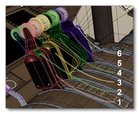
Multi-component objects such as complicated throttles should be named in relation to each other, for example:
 |
|
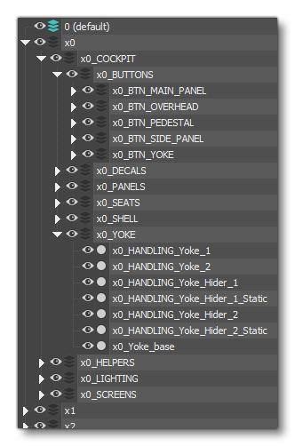
The image below shows further examples of how things should be named and their hierarchy within 3DS Max: