THE CAMERAS TAB

The Cameras Tab is used to set up some of the basic properties related to the camera used when flying in the simulation. This tab is split into the sections listed below.
Views
 This section has the following parameters and is used to determine the base position of the cockpit camera (note that all the camera definitions will be defined relative to this point):
- Eyepoint: Here you can set the Longitudinal, Lateral and Vertical distance from the center of the aircraft model for the camera. This point may be positioned visually within the simulation by checking the Show Gizmo checkbox.
- External Camera Distance: If the value given here is positive, it will be used as the priority distance for the camera (in feet) from the aircraft. If set to 0 or a negative value, then the following rules will be applied to the camera distance:
-
For airplanes the distance will be (depending on circumstances)
- the wingspan multiplied by 1.2 or,
- the shadow sphere radius multiplied by 1.75 or,
- the wing chord (calculated by wing area and wingspan) multiplied by the Camera Distance Coefficient or,
- 11 meters by default in case of failed data loading. -
For helicopters the distance will be (depending on circumstances)
- rotor diameter multiplied by 1.2 or,
- shadow sphere radius multiplied by 1.75 or,
- shadow sphere radius over rotor diameter, multiplied by the Camera Distance Coefficient or,
- 11 meters by default in case of failed data loading.
-
-
Camera Distance Coefficient: This value will be used as a multiplier on the camera distance under certain circumstances, and when the External Camera Distance has not been set manually.
Camera Ray Node Collision
 This section permits you to define up to 10 different nodes on the user aircraft model (interior and/or exterior) with which to check if the camera is "pointing" at them, using a ray traced from the camera. This camera ray is defined as coming from a point in the center of the FOV of the camera and going "forward" relative to the camera angle. Once you have defined these nodes, you can then use the SimVar
 IS CAMERA RAY INTERSECT WITH NODE to check for collisions. To add a node, you can click on the + button, and to remove it you can click the x button. Each node has the following parameters:
- Model Definition: This sets where the node is, and can be either Interior or Exterior.
- Name: This is the name of the node as defined in the glTF file.
Camera Definition

In this section you can create multiple cameras for a single aircraft. Each camera can be added by clicking on the + button at the bottom, or removed using the x button.
IMPORTANT! The first camera to be defined (0), must have the Category set to Cockpit, and have the Pilot subcategory, otherwise the camera file will not be parsed correctly.
Below are all the parameters required for setting up the various cameras that you want to have for the aircraft:
- Title: This is descriptive only, not used by the system
- UI Title: This is a localisable string that will be used to show the name of the camera in the simulation UI. Note that this should always be formatted using "TT", eg:
TT:my_company_aircraft_name
- GUID: Camera definition's unique identifier. This GUID must be unique.
- Description: A brief description of the camera.
- Category: Every camera definition must include a category that defines how the camera is exposed in the user interface. Categories define the view cycling behavior as well as the menu structure. Some categories (AirTraffic, Runway, Multiplayer and Tower) can also be instance-based, meaning new cameras are created automatically based on the object type. Available categories are (the most commonly used ones have additional explanations):
- Aircraft - For shifting the default external camera original position (title must be
DEFAULT_CHASEor name of an flight state) - AirTraffic
- Cockpit - For the cockpit camera's default position (first one), then for instrument cycle. This is also the category that is used to define the shadow sphere (see Notes For The Shadow Sphere for more information). The first camera definition should always be for the Cockpit, and also always have the Pilot sub-category.
- Custom - For the Quickviews. Always in this order: left, down, right, up
- Outside
- Multiplayer
- Runway
- Scenery
- Tower
- FixedOnPlane - For cameras fixed to the object
- Aircraft - For shifting the default external camera original position (title must be
- Sub Category: You can specify the principle role of the camera with the "subcategory". This defines the context we need the user to view from the following options:
-
Pilot - The view can be used by the cockpit to load any "pilot" view, like VFR, IFR, Landing, Copilot, etc...
-
Instrument - Allow you to define an instrument camera which we can cycle through while in instrument view.
-
QuickView - Allow you to define a Quickview camera which we can cycle through while in the Quickview view.
-
CheckList - Any Checklist view
-
Custom - Used to create a custom view.
-
FixedOnPlaneIntern - Allows you to define a fixed camera on one place in the interior of the object
-
FixedOnPlaneExtern - Allows you to define a fixed camera on one place on the exterior of the object
-
Shadow Center - Used only to specify a correct position of shaders for the interior model. Please see the
-
- Sub Category Item: This is used to specify a unique view. For each object, you can only have one of those views linked to a particular Subcategory/ Category combo, for example - Aircraft/ Quickview can have only one QuickView1. But Cockpit/ Quickview can also have one. SubCategoryItem can only be used with its linked SubCategory, and can be any one of the following:
-
ClosePilot (Subcategory:Pilot) - Pilot view specialized for IFR flight (better view on instruments)
-
DefaultPilot (Subcategory:Pilot) - Pilot view specialized for VFR flight (better view on scenery)
-
LandingPilot (Subcategory:Pilot) - Pilot view specialized for Landing (better view on ground)
-
CoPilot (Subcategory:Pilot) - Pilot view place at the copilot position
-
TrueCockpit (Subcategory:Pilot) - Pilot view for homemade cockpits (centered, cockpit hidden)
-
QuickView1...8 (Subcategory:QuickView)
-
PilotVR (Subcategory:Pilot) - Pilot view used when VR is active.
-
- Initial XYZ: Camera XYZ position offset from the default location. All values are in meters. Note that you can position the camera within the simulation and then click on the
Get Pos From Simbutton, which will then use the current developer camera position to generate the offset values. This is also used to define the shadow sphere position (see Notes For The Shadow Sphere for more information).
- Initial PBH: Camera pitch, bank and heading orientation offset from the default in degrees. Note that positive pitches give a downward view, and positive headings are to the right, and all values are in degrees. Note that you can position the camera within the simulation and then click on the
Get Rot From Simbutton, which will then use the current developer camera pitch/bank/heading to generate the orientation offset values.IMPORTANT! When using the Cockpit camera, the "bank" value will be ignored.NOTE: This parameter is not used when the SubCategoryItem is set to "PilotVR".
- Initial Zoom: Sets the initial camera zoom level. Note that you set the camera zoom within the simulation and then click on the
Get Zoom From Simbutton, which will then use the current zoom level to generate the offset values
- VarToggle: This parameter functions as a simple toggle for local variables. You supply one (or more)
L:Vars and then when the camera is active the variable will be toggled to 1 (TRUE) and when it is deactivated it will be toggled to 0 (FALSE). This is useful, in particular when using different model behaviours - for example using the visibility template to to hide the yoke when a specific camera that is viewing an instrument. Note that this toggle of theL:var will only happen if it's value is less than one when the camera is selected. If it is already 1 (or greater) then the toggle will not happen, and that includes it being set to 0 on switching away from the camera. To add a newL:var you can click the+button then give the name of the node that you want to hide. You can remove any of theL:vars by selecting it then clicking thexbutton.
- Bounding Box Radius: Allows you to define a bounding box to the camera - in meters - which can be used with the instrument camera to give more or less "space" between the camera and the instrument auto selection and the focus with the mouse going over it. This is also used to define the size of the shadow sphere (see Notes For The Shadow Sphere for more information).
- Chase Distance: The initial distance (in meters) of the camera from the target object in external views.
- Chase Heading: Initial angular offset in degrees of the camera relative to the target object in external views.
- Chase Altitude: Initial altitude in feet of the camera relative to the target object in external views.
- Chase Time: Length of time in seconds an aircraft is kept in Fly-By view before a new position is computed.
- Chase Distance Adjust Rate: This controls the rate at which chase distance changes when incremented or decremented using key events.
- External Camera Follows Heading: This sets the speed (in ktas) below which the external camera should follow the aircraft heading.
- External Camera Follows Velocity: This sets the speed (in ktas) above which the external camera should follow the aircraft velocity vector.
- HotKey Select: Links the camera to one of the 10 pre-defined key events for activating cameras.
Finally you have three extra buttons that can be used to help you when defining cameras. These are:
Get From Sim
When you click this button, the editor will take the position, orientation and zoom factor of the camera - as positioned in the simulation - and apply the value to the Initial XYZ, Initial PBH and Initial Zoom fields.
Teleport On Camera
Clicking this button will position the camera within the simulation using the currently selected Camera Definition. This permits you to preview how the camera will look when being used.
Save And Reload
This button will save the Camera files, as well as all the other aircraft editor files, and then reload the simulation so that the camera settings are applied. This is required for properly testing cameras, since the Save And Resync option will not apply camera changes (but it will save them).
IMPORTANT! Since this button will save restart the current flight when it is used, ensure that all the other sections of the Aircraft Editor are correctly configured as they will be saved too
Notes For The Shadow Sphere
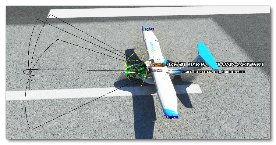
The Cameras tab is also used to define the properties of the Shadow Sphere, which is the area that defines the first shadow map for the aircraft (shown in yellow when the Shadow Sphere debug option is enabled):
 The process for defining the shadow sphere is very simple as it only requires that you set up a small subsection of the aircraft editor camera parameters, namely:
- The Origin, which should be "Cockpit"
- The Category, which should also be "Cockpit"
- The Sub-Category, which must be "Shadow center".
Once you have made those selections you can edit the Initial XYZ values to position the shadow sphere correctly within the cockpit space, and then finally edit the Bounding Box Radius parameter to set the size of the shadow sphere.