BASIC AERODYNAMICS
With our spreadsheet filled out, our aircraft loaded into Microsoft Flight Simulator, and our POH in and other resources ready, we can start to edit the various CFG files. We're going to start by editing the flight_model.cfg to get the basic aerodynamic parameters setup correctly, but before continuing, make sure you have the Aircraft Editor open and on the Aerodynamics section, and we also suggest that you open the Pitch debug window. This will show you an overlay of the virtual wind-tunnel which is used to visualise and calibrate the parameters that are entered here.

The use of geometric information and a surface-based simulation reduces the need for aerodynamic performance data to the strict minimum. However, it is impossible to get exactly the right values and performance just based on geometry... Each aircraft has little imperfections - forms and shapes that are too small and complex to be perfectly simulated in real time - and for that reason we use a normalization system. By entering a very small set of performance values you can define the target performance you need for the aircraft. Then, in order to achieve the performance values you've entered, the aircraft is run through a virtual wind tunnel in real time and the sim performs 100 adjustment iterations to the surface aerodynamic parameters. For this reason, we'll be starting with the minimum basic aerodynamic values required for an aircraft before moving on to the actual geometry.
\(C_{Lmax1}\) - Maximum Lift Coefficient without flaps
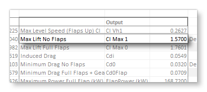
The maximum lift coefficient (without flaps) is what we'll use to fill in the lift_coef_aoa_table. You can set these values from the Aerodynamics panel in the aircraft editor, scrolling down to the AoA Tables section:
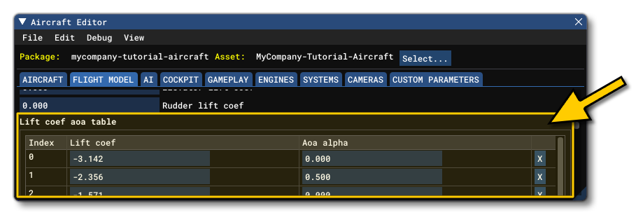
You may also edit the table directly in the flight_model.cfg under the [AERODYNAMICS] section as a comma separated list where each entry is [AoA(rads)]:[Coefficient], eg:
lift_coef_aoa_table = -3.15:0, -0.8:-1.029, -0.4:-0.789, -0.2:-0.572, -0.1:-0.375, 0:0.257, 0.2:1.408, 0.23:1.474, 0.26:1.5416, 0.29:1.528, 0.31:1.466, 0.4:0.842, 0.8:1.046, 3.15:0
The most important value here is the one that we'll be applying the \(C_{Lmax1}\) value too, which is the maximum lift that an aircraft has just before the stall point, which is usually somewhere between 16° and 20°.
IMPORTANT! The surface-based flight model used in Microsoft Flight Simulator works in full 3D and simulates the airflow over the aircraft, whatever its direction. However, we the aircraft performance is normalized to the airflow moving on the longitudinal axis, with AoA between 0° and 15°. For airflows that would move 100% laterally or vertically, we use standard aerodynamics surface definitions that cannot currently be changed. These situations however are either impossible or extremely rare in normal flight and really only have a small importance for aerobatics.
The following example from the flight_model.cfg file shows where this appears in a typical table:

Now, this table can have a maximum of 13 entries to define the curve, but only a sub-section of those values will be used when creating the wind tunnel normalization using the Microsoft Flight Simulator aerodynamics model. The other values are necessary only for compatibility with the legacy (FSX) simulation and can be ignored at this stage. So a simplified table at this stage would look like this:
lift_coef_aoa_table = -3.15:0, -0.8:-1.029, 0:0.257, 0.26:1.5416, 3.15:0
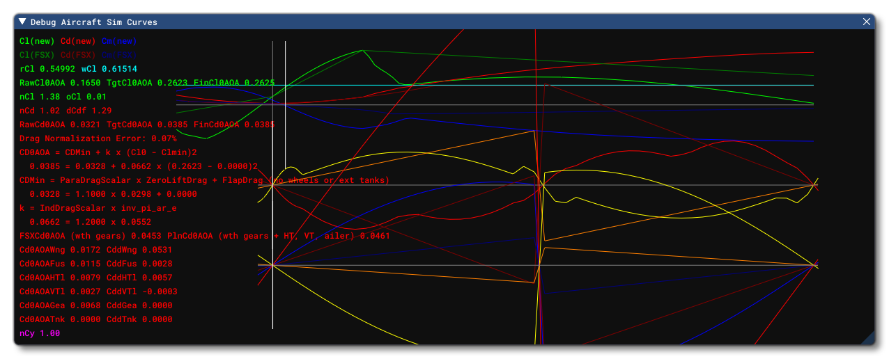
It's worth noting that to help understand the lift and drag curves of the aircraft, you can enable the Sim Curves debug option in the Aircraft Editor:
Delta Lift And Delta Drag
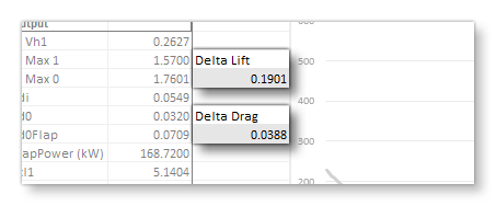
If the aircraft has flaps you should now define the Delta Lift and Delta Drag coefficients. These values will be added when the flaps are fully deployed and can be defined in the Aerodynamics panel in the aircraft editor:
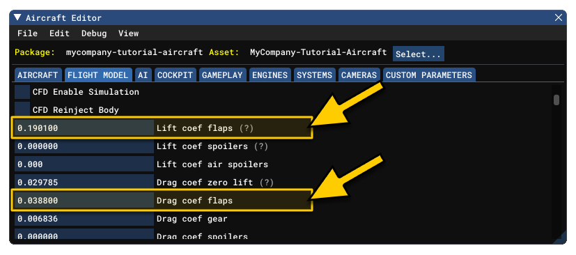 You can edit these directly by changing the values of the
 lift_coef_flaps and drag_coef_flaps parameters in the flight_model.cfg.
In previous iterations of Microsoft Flight Simulator, the lift and drag bonuses for flaps were added to the lift and drag calculations that resolved automatically from the simulation. However, now these bonuses are used for surface deflection and wind tunnel normalization (the addition of the lift coefficient cannot be achieved as before since it is not physically correct at all angles of attack). This surface deflection and wind-tunnel normalization guarantees that the total lift and drag added will correspond to the indicated values at the stall angle of attack. At an angle of attack of zero, the resulting increase of lift and drag is usually about half as much and at negative angles of attack, the effect tends to wash out completely. This is a major improvement compared to previous simulations which would have very large and incorrect lift/drag coefficients at negative angles of attack.
\(C_{D0}\) - Minimum Drag No Flaps
 We need to add in the Minimum Drag No Flaps value, which is used to fill in the Zero Lift field in the Aircraft Editor (under the Drag tab), or the
 drag_coef_zero_lift parameter in the flight_model.cfg.
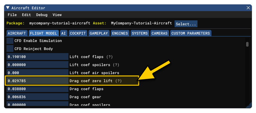
This needs to be set with the aircraft in a clean, cruise configuration, with the landing gear excluded. If the landing gear can be retracted this will give you the minimum drag of the aircraft. If the landing gear cannot be retracted, you will need to subtract the gear drag coefficient (see the section Gear Drag Coefficient, below). It's also worth noting that you can make some generalisations about this value so you can check that you have it more or less correct in the spreadsheet:
- this value is usually around 0.02 to 0.025 for an aircraft with a glide ratio above 15
- this value is usually around 0.03 to 0.04 for aircraft with glide ratios of about 10
- this value can be up to 0.1 for some aircraft with very low glide ratios
Gear Drag Coefficient
This value does not appear on the spreadsheet since the spreadsheet computes cruise performance in cruise configuration only and so needs to be calculated empirically. With reference to the spreadsheet you have to consider that:
- Some planes have retractable gears, so the spreadsheet \(C_D\) is for the fuselage only. For example, the TBM would simply be calculated as
drag_coef_zero_lift= \(C_D\) from the spreadsheet. - Some planes cannot retract their gears, so the spreadsheet \(C_D\) is for the sum of the fuselage and the gears. So the actual fuselage \(C_D\) that we need is the one from the spreadsheet minus the gear drag coefficient (as explained in point 3, above). For example, the C172 would be calculated as
drag_coef_zero_lift+drag_coef_gear= \(C_D\) from the spreadsheet.
The gear drag coefficient is placed in the Gear field in the Aircraft Editor (under the Drag tab), or the drag_coef_gear parameter in the flight_model.cfg.
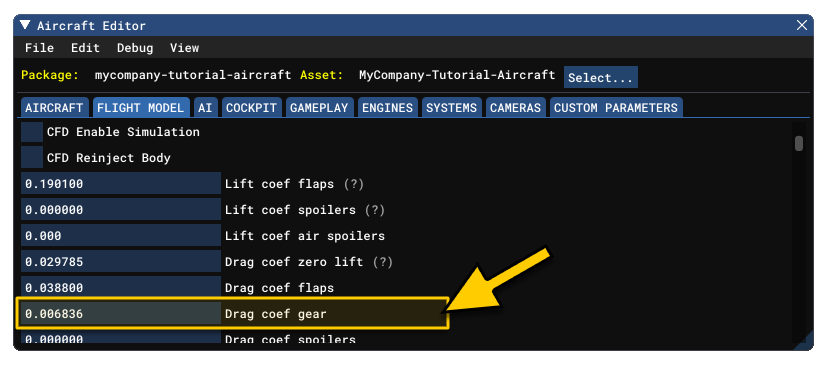
The actual gear drag coefficient is incredibly difficult to find, so you will have to set an approximate value then tweak things to suit. Note that, in general, the value will always be between 0.005 and 0.01 depending on the aircraft.
\(C_{L0}\) Lift Coefficient At Drag Zero
After setting these values, you'll need to set the \(C_{L0}\) value, which is the lift the aircraft produces when the drag is minimum. Legacy simulations used this simplified drag formula:
$$C_D = C_{D0} + K \times {C_L} ^{2}$$
The problem with this simplified formula is that it only allowed you to simulate planes that had their minimum drag when the lift coefficient was zero, and this is rarely the case. In clean configurations, many planes have their minimum drag at lift coefficients of around 0.1 and in full flap configurations, that parameter can go up to 0.4. The Microsoft Flight Simulator system is normalized to a drag polar that follows this more accurate formula:
$$C_D = C_{D0} + K \times (C_L - C_{L0}) ^{2}$$
Where:
$$K = \frac {\textrm{induced_drag_scalar}} {(\pi \times AR \times \textrm{oswald_efficiency_factor})}$$
Note that in steps 6 and 7 (below) we'll deal with the induced_drag_scalar and oswald_efficiency_factor terms.
So we need to define \(C_{L0}\), which is the lift coefficient that is generated when the plane produces minimum drag, defined in the flight_model.cfg using the lift_coef_at_drag_zero parameter. If you know this value exactly, then use it here, and if not then this value - for most planes - will be about 0.2 to 0.4.
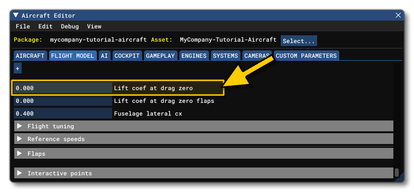
Lift Impact
Now we need to define how lift impacts drag, so that the wind tunnel normalization system can adjust the surfaces to match the right drag polar. This is achieved through setting the Oswald Efficiency Factor, which can be done from the Geometry section of the Aircraft Editor, or by setting the oswald_efficiency_factor parameter in the flight_model.cfg file.
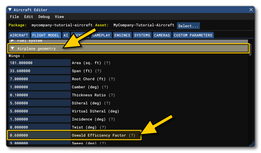
If you know the Oswald coefficient of the plane then use it. If not, the Oswald is usually between 0.7 and 0.8, with 0.75 being a good default value.
Induced Drag Scalar
We should now set the induced drag scalar for the aircraft. We need to set this because it's involved in the calculations for the \(C_{L0}\) value that we added previously (see Lift Coefficient At Drag Zero, above). Basically, the \(C_{L0}\) value shifts the lift drag polar but will also reduce the induced drag by quite a bit and therefor reduces the drag close to stall speeds too much. So, if there is a non-zero \(C_{L0}\) value, you will need an induced drag scalar that is larger than 1.0.
You can set this value from the Flight Tuning section of the Aircraft Editor, or by setting the induced_drag_scalar in the flight_model.cfg.
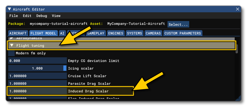 If you have this value, use it here but if not, then a value between 1.2 and 1.5 is usually fine. Note that if this value is above 1.5, then the plane will generate a lot of drag at slow speed, and if the value is closer to 1, it will glide very easily at slow speeds.
Flaps
NOTE: If the aircraft does not have flaps, you can leave all parameters in this section set to 0.The next step for setting up the basic aircraft aerodynamics is to setup the flaps. Flaps are edited from the Flaps section of the Aircraft Editor, or by editing the flaps-position.i parameter directly in the config file.

In the editor you would add each flap to the section on the left, then fill in the details on the right. You should, at this point, be paying particular attention to the positions (stages) listed at the bottom (corresponding to the flaps-position.i parameter in the CFG file). There are a number of values that you can set here, but for each position of the flap, it's the first three that are the most important:
- Pos: the flaps position angle for the stage.
- Max Speed: sets the airspeed limit for the stage, in Knots (can be left at -1 to tell the sim that there is no limit)
- Drag Coeff: sets a scalar to add or remove drag for the stage.
You should be increasing the drag coefficient with the flap stage so that the scalar reaches a value of 1 when at full flaps. In the CFG file, a basic setup for a flap would look like this:
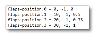
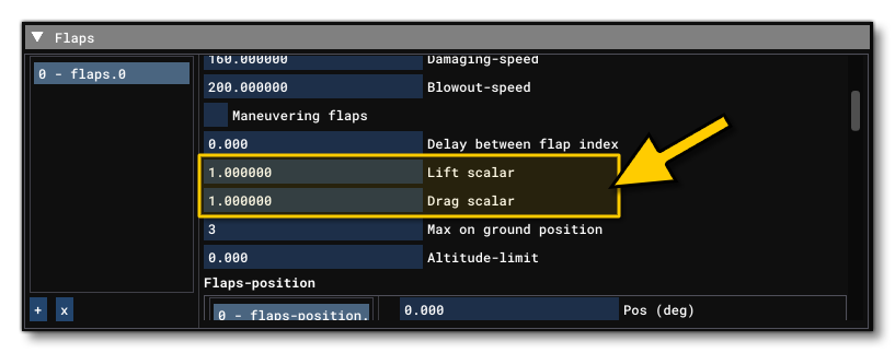
You should also set the lift and drag scalar values for each of the flaps on the aircraft. This is required because the flight model here relies on a legacy calculation that is no longer entirely accurate for Microsoft Flight Simulator. Essentially, the system multiplies the lift_coef_flaps and drag_coef_flaps by the flaps deflection angle in radians, and so for a 45° maximum flaps (for example) we get 0.78 radians, which in turn means that the drag and lift are multiplied by 0.78. This is incorrect and needs to be modified using the lift and drag scalars, which you can find from the Flaps section in the Aircraft Editor, or you can edit them directly by changing the lift_scalar and drag_scalar parameters in the flight_model.cfg.
 NOTE: The flaps pitch scalar value is no longer used by the simulation and can be ignored
The value to be placed in the scalars is actually very simple to calculate:
- Get the maximum angle of deflection for the flap, for example 30°.
- Convert it into a value in radians, for example with our value of 30° we get 0.524 radians.
- Divide 1 by the value in radians, for example \(\frac {1}{0.524} = 1.908\).
The resulting value (1.908 in our example) is what will be used for the lift and drag scalar parameters.
Spoilers
NOTE: If the aircraft does not have spoilers, you can leave all parameters in this section set to 0.You can define the lift and drag coefficients that will be added when the spoilers are fully deployed from the AERODYNAMICS panel, on the Lift and Drag tabs, respectively (both input fields are simply labeled Spoilers). In the flight_model.cfg file, these are the lift_coef_spoilers and drag_coef_spoilers parameters.
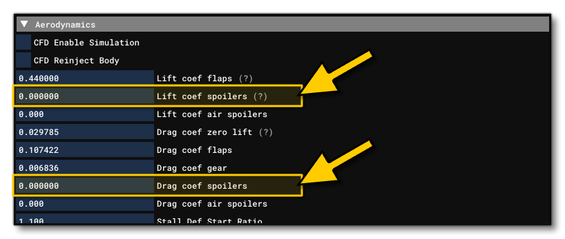
Based on the coefficients you enter here, an equation will be solved to compute the required deflection of the surfaces in the underlying surface based aerodynamics model. Then, the plane with the resulting spoiler deflection will be run 100 times through the virtual wind tunnel and the exact deflection will be readjusted to achieve the exact lift coefficient change desired. Advanced effects such as pitch moment generated by spoilers will be automatically simulated based on the actual surface aerodynamics simulation and cannot be adjusted.