PISTON ENGINES
Piston engines are one of the most common type of engines in the general aviation world. Unlike the Turbine Engines their only means of generating thrust is by using one or more Propellers. On this page we'll go into the details of how to create the initial setup for these engines and get things to a point where you can start to tweak the values and edit more advanced options so the aircraft engine behavior matches that of the real thing.

The Piston Engine Simulation
Before getting to the parameters that you will need to set up initially, it's worthwhile taking a moment to understand how Microsoft Flight Simulator simulates piston engines. In general the simulation is fairly simple and consists of the following calculations, in the given order:
- Compute the carburetor temperature:
- Induction temperature only, with effects due to:
- ambient atmosphere where temperature equals the ambient temperature
- the turbocharger which compresses air, heating it up in the process
- the carburetor heat which is used to heat up induction air
- Addition of icing effects:
- taking into account carburetor sensibility
- Addition of fuel vaporisation temperature drop:
- The only param that affects this is the Induction Air Temperature Time Constant.
- Induction temperature only, with effects due to:
- If the engine is a diesel engine, the glow plug temperature is computed
- Compute the effect of the starter on torque, etc... (note that this has low impact on performance)
- Compute engine power:
- Thermodynamics calculations following the steps of the engine cycle: intake, compression, combustion, power, exhaust
- Induction (or carburetor) temperature is taken into account on the intake step as well as the manifold air pressure. Manifold air pressure varies depending on whether or not the engine is naturally aspirated, the throttle input, and the ambient pressure.
- Higher manifold air pressure leads to higher power
- The compression phase is mainly driven by values calculated from the compression ratio given in the Aircraft Editor.
- Higher ratio leads to higher power
- Power is now computed following these different steps:
- Compute all the effects of the following different systems and parts:
- Magneto - are both running or not? Running on a single magneto leads to less power.
- Mixture setting - depending on the mixture setting more or less power is generated. The closer you get to the ideal mixture ratio the higher the power.
- Cylinder damage - evaluation of the cylinders health which will "scale" the power output. Damaged cylinders leads to less power.
- Cooling - if the engine is liquid cooled, the engine will lose power depending on the coolant level in the coolant tank.
- Engine damage due to WEP - if too much time has been spent in the WEP power setting, the engine will output less power.
- Primer effect - more or less primer is required depending on the outside temperature. If the General engine parameter requires priming is true, then the engine won't start if the primed level is not sufficient.
- compute work and shaft torque from it.
- compute mechanical efficiency \(eta_{mechanical}\) from a table
- compute friction from a table
- Final Shaft torque is:
$$final\_shaft\_torque = (shaft\_torque * \eta_{mechanical}- friction*N_{cylinder})*power\_scalar$$ - If the engine is supercharged :
$$final\_shaft\_torque = (shaft\_torque * \eta_{mechanical}- friction*N_{cylinder})*power\_scalar * (1-supercharger\_cost)$$
- Compute all the effects of the following different systems and parts:
- Compute the different pressures and temperatures (none this will have a direct effect on performance):
- EGT
- Cylinder head temperature
- Oil pressure / temperature
- fuel
- radiator (coolant)
- The resulting shaft torque is then used in the propeller code to drive the propeller which in turn will generate thrust.
Power Output
Before setting up the actual piston engine parameters, it's worth taking a moment to discuss in a bit more depth the Max Rated HP parameter. THis parameter has to be set, but it should be noted that this does not control the actual power output of the engine, and it is instead used in EGT calculations and fuel flow calculations. You will be adjusting the power output using other parameters in an attempt to equal this value.
To check the actualpower output of an engine you can do one of two things:
- Monitor the SimVar
RECIP ENG BRAKE POWER:[engine_index] - Use the Engines Debug Window and watch the CurHP value

Another important thing to keep in mind is that the power rating of engines is given at sea level at a standard (or close to standard) atmosphere, and static. When testing an engine in the simulation, these conditions should be met to ensure that it produces the correct amount of power.
Engine Tuning
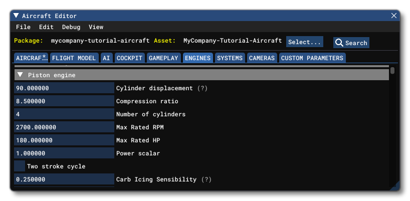
The first step of engine tuning is to do doing some research on what are (or were) the specifications and ratings of the engine being replicated. Then, once enough information has been gathered, it is possible to start describing the engine specs by setting the correct values for the following parameters:

- Cylinder Displacement (
cylinder_displacement): This is the cylinder displacement for a single cylinder in cubic inches, and the value given here will affect the cylinder torque, based on the following formula
$$Displacement_{cylinder}=\frac{Displacement_{total}}{N_{cylinder}}$$
- Compression Ratio (
compression_ratio): This is the compression ratio for a single cylinder, and it too will affect the cylinder torque. This value can sometimes be tricky to find, so here's an approximation that is a good base to start from:8 < compression ratio < 9for modern engines (eg: Lycoming (AE)(I)O-360)6 < compression ratio < 7for older engines (eg: V-1650-7 Merlin {P-51D}, BMW 132 {JU-52}, etc...)
-
Number Of Cylinders (
number_of_cylinders): The engine cylinder count, which will affect the total torque sum of all cylinder torques and the total engine friction of all cylinders.
-
Max Rated RPM (
max_rated_rpm): The maximum rated RPM of the piston engine. Should be set to the actual aircraft max rated rpm and should not be used to tweak engine performance.
-
Max Rated HP (
max_rated_hp): The maximum rated power of the piston engine. Should be set to the actual aircraft max rated power and not be used to tweak engine performance. This value is affected by the Power Scalar, and has a direct impact on fuel flow but no direct impact on engine torque or output power. The output power needs to be adjusted to actually meet this value, as it won't be met automatically.
-
Power Scalar (
power_scalar): This scalar should be set to 1.0 when you start tuning the engine and only adjusted if required. The value given here is used to ponderate the Max Rated HP value, scaling the net torque / power output of the engine that is transferred to the propeller.
Once those are set up, you should then scroll down through the Aircraft Editor parameters and set the Fuel Metering Type (fuel_metering_type), which is the ECU or the ICU deciding how much fuel to inject into the cylinder. This can be one of the following:
- Fuel Injected
- Gravity Carburetor
- Aerobatic Carburetor

With that done, you will now want to look at the following two tables:
- Mechanical Efficiency (
engine_mechanical_efficiency_table): This table represents the engine rotation speed (RPM) versus the different mechanical efficiency factors for the given speeds, and this table that will be applied to the torque formula. We recommend setting up this table with the values shown in the image above to start with.
 - Friction (
engine_friction_table):
 This table defines the friction/torque applied to the engine - especially when shutting down - and each element in the table requires you to set the RPM for engine rotation speeds and correlate them with the torque (in ftlbs). This is another of the friction scalars that will be applied to the cylinder friction as part of the torque formula. As before, we recommend setting up this table with the values shown in the image above to start with.
From this point on, you can adjust the way these tables are used by manipulating the following scalars based on your needs (the values shown are for a high efficiency/high friction approach):

- Max RPM Mech. Eff. Scalar (
max_rpm_mechanical_efficiency_scalar) - Idle RPM Mech. Eff. Scalar (
idle_rpm_mechanical_efficiency_scalar) - Max RPM Friction Scalar (
max_rpm_friction_scalar) - Idle RPM Friction Scalar (
idle_rpm_friction_scalar)
For these parameters you should note the following:
- Efficiency is a multiplier on torque which means that it scales a lot with throttle input.
- Friction is subtracted from torque which means it does not scale by itself.
- In real life, engines are more efficient at low RPM, and in the simulation - since friction is handled separately - efficiency can be tuned according to the needs of the aircraft designer.
- Higher efficiency means more torque (thus, more power) and higher friction means less torque (thus, less power).
- Friction generally increases with RPM.
- Aiming for rather high efficiency at low RPM coupled with high friction will give good responsiveness to the engine.
As a general rule, it is practical to start by tuning the engine to have the desired idle RPM, then check to see if the power output is correct (or correct enough). Then you can start adjusting it with the max RPM scalar and then re-adjusting for correct idle speed with the low RPM scalar. We do it this way because changing the max RPM scalar will also affect the final value at low RPM but to a lesser degree than when using the low RPM scalar.
If this is still not giving you the correct result, you can then start to edit the tables directly to get more control on the torque behavior. Also note that very low RPM entries in the mechanical efficiency table are usually not 1.0 to have better control of how the propeller will stop.
Pressure And Temperature
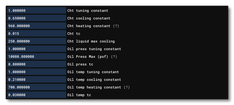
In the previous section you set up the Fuel Flow Scalar and here you also need to set the Oil Pressure Max (oil_press_max) value, in psf:

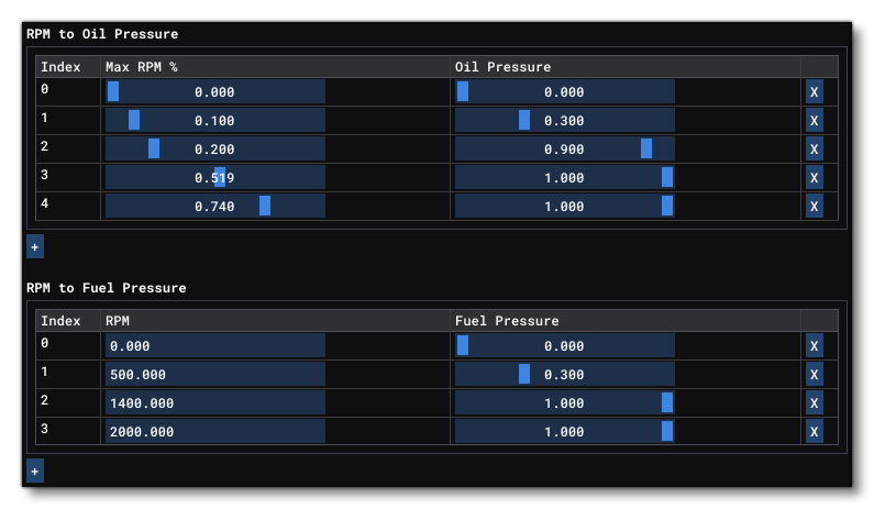
With that set, you should also go through the RPM To Oil Pressure (rpm_to_oil_pressure_table) and RPM To Fuel Pressure (rpm_to_fuel_pressure_table) tables which simply give the correlation between RPM and pressure in psf:

Setting the various temperature parameters is a little more tricky, as it is based on the following inputs:
- a maximum temperature (heating constant) parameter
- a table giving temperature vs. RPM
- a cooling constant
- a time constant (tc)
- a tuning constant

The temperature calculations basically follow these steps:
- Raw temperature evaluation, calculated as: \(\textrm{heating_constant} \times interpolation(\textrm{temp vs RPM table})\)
- Evaluation of cooling: \(\textrm{cooling_constant} \times airspeed \times \frac {ambient\_density}{standard\_sea\_level\_density} \times \frac{ambient\_temperature}{standard\_sea\_level\_temperature}\)
- Local temperature: \(\textrm{Raw_temperature} - cooling\)
- Local temperature is then integrated
When working out the values for these parameters, you should reference the POH, which usually indicates the temperatures the pilot should aim for, or at least those which you should not reach when flying. When tuning oil temperature, the RPM To Oil Temperature Factor (oil_temp_factor_from_rpm) table should be set such that the raw temperature will be higher than that stated in the POH. Note that when performing temperature tuning, you should be taking into account the possibility for overheating, so you should also be tuning the different cooling constants so that flying around will bring a high temperature back down. This allows to you have overheating when using full power, but are static on the ground.
Additional Components
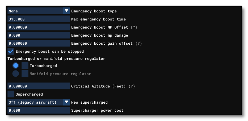
If the aircraft you are modelling has additional components then these should be set up now, at least in an approximate manner, as they can be tweaked and modified as you perfect the flight model. Additional components include:
- Supercharger (
supercharged) - Turbocharger (
turbocharged) - WEP / Emergency Boost (
emergency_boost_type) - Auto Mixture Control (
fuel_air_auto_mixture) - etc...

It is also worth considering the following documentation when adding a supercharger or emergency boost to the aircraft: