FINE TUNING
By now you should have set up a rudimentary flight model that defines the geometry, the aerodynamics, the engines, the fuel system, and the electrics for the aircraft. At this point you can test the aircraft and it should fly and behave fairly similarly to the "real" aircraft, however there will almost certainly be differences and issues. So, this means you need to do some "fine tuning" of the flight model which is what we'll discuss on this page.
IMPORTANT: Even after performing this fine tuning, your aircraft will not be completely correct in its behavior and handling. There are a vast number of components available and each aircraft will require a unique combination of parameters and values to fly correctly. This is something that is impossible for us to cover in a tutorial and as such the idea is that at the end of this section you have a more-or-less working aircraft that you can then refine using:
- the various debug windows
- the documentation for each parameter
- the information gained form the POH and other sources
- your own intuition for how it "feels" when flying
Define Moments Of Inertia
You should have already set up the everything that influences the weight of the aircraft and the distribution of that weight over its volume, so now it is time to set the empty aircraft MOIs. These are edited in the Aircraft Editor Weight And Balance section of the Flight Model tab, or through the [WEIGHT_AND_BALANCE] section of the flight_model.cfg file:
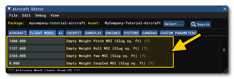
- Empty Weight Pitch MOI (
empty_weight_pitch_MOI): The pitch MOI, in Slug sqft, when the aircraft is empty.
- Empty Weight Roll MOI (
empty_weight_roll_MOI): The roll MOI, in Slug sqft, when the aircraft is empty.
- Empty Weight Yaw MOI (
empty_weight_yaw_MOI): The yaw MOI, in Slug sqft, when the aircraft is empty.
- Empty Weight Coupled MOI (
empty_weight_coupled_MOI): The empty transverse MOI, in Slug sqft, when the aircraft is empty.
If you have the data available for these setting then you should always use it, but if not, then you can use the Debug menu in the Aircraft Editor and select the Weight debug window. Here you can find the estimated typical empty MOI values:
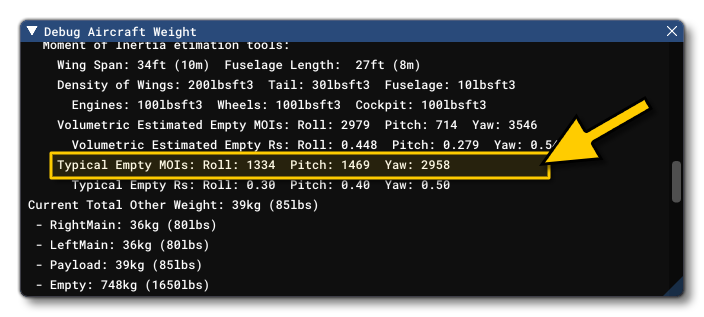
These MOIs are calculated based on the dimensions and geometric shape of the aircraft, and you can use these values to fill in the parameters in the Aircraft Editor, then tweak them as required.
Advanced Wing Effects
The following explains the specific sections that should be modified at this point to perfect the flight model for the aircraft with relation to the aircraft geometry.
Wing Camber
The wing Camber parameter (wing_camber) tells the simulation how the airflow will affect the lift forces as it moves over the wing:

When the airflow is moving over the wing, it is bent, and the air particles are first accelerating upwards a little and then they accelerate downwards a lot. The resulting reaction is what creates lift on the wing: when the air particles accelerate downwards, the wing accelerates upwards which corresponds to the lift force. This uneven acceleration of air particles, up first and then down, creates a moment on the surface, and the larger the difference, the more the wing will want to pitch down. This effect is fully automatic but the wing camber parameter allows you to define how much of the effect you want to get by altering the convexity of the wing itself. Basically, the more the wing is cambered, the larger the difference between the up and then down acceleration of the air, and the larger the pitch moment.
The following illustration helps show how this affects the actual simulated wing geometry:
 As you can see, the simulation does not model a fully curved wing surface, but instead creates an upper "front" surface and an upper "back" surface, as well as the corresponding lower surfaces. The camber is the difference in angle between those surfaces, and the mean camber line is calculated along the geometric center of the wing at half-wing thickness. Note that the current flight model does not permit setting the camber for the top and bottom surfaces independently, and the bottom camber will be derived in symmetry with the top surface camber. Also note that the value cannot be 0 and inputing a value of 0 will force the flght model to a default value of 1.
Wing Incidence
Most aircraft have some wing incidence to produce some quantity of lift when the aircraft pitch/AoA is zero, which set using the Incidence parameter (wing_incidence):

Within the simulation, all aircraft are normalized through a virtual wind tunnel, which means that the overall lift and drag curves will correspond to the data defined for the base aerodynamic parameters, ie: incidence is the average chord incidence, and normalisation will change the incidence to get the target lift polar. The best result is always when normalisation makes zero changes, which will happen when the defined geometry of the plane matches the defined performance. The further apart the geometry and the expected performabnce are, the more the normalisation will change the incidence.
Note that setting the correct wing incidence will affect each simulated wing surface and will have an effect on the exact level of lift and drag, depending on the pitch of the aircraft. Just like the definition of wing twist, it will slightly change the shape of the lift and drag curves, without changing the lift and drag values at maximum and zero AoA.
Wing Twist
The Twist parameter (wing_twist) affects the incidence angle of the surfaces:

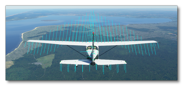
On most aircraft, the incidence at the exterior edge of the wing is lower than the incidence close to the fuselage. Now, because wings stall at a given angle of attack, this twist allows the stall to occur in the middle of the wing first and then to propagate towards the end of the wing. While this happens, and because the end is not stalled yet, the ailerons will remain effective allowing roll control over the aircraft. This effect is an important component of whether the aircraft will enter a spin when it stalls.
Twist is computed from wing root to wing tip around the average chord incidence, as shown below:

Note too that the wing twist value may result in the wing producing negative lift at the outside and positive lift close to the fuselage when flying at high speeds.
Adverse Yaw
Adverse yaw is the natural and undesirable tendency for an aircraft to yaw in the opposite direction of a roll.
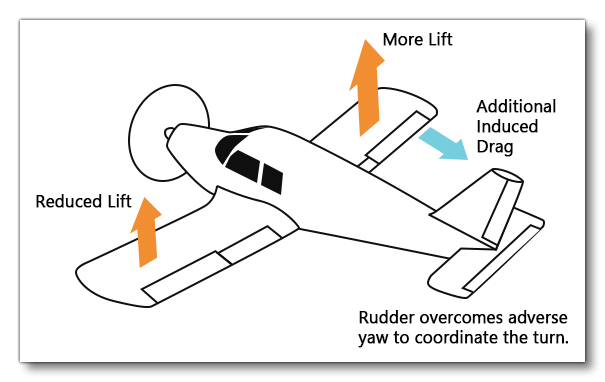 It is caused by the difference in lift and drag of each wing, and to modify this and create a more realistic simulation you can edit the Aileron Up Drag Coefficient and Aileron Down Drag Coefficient (
aileron_up_drag_coef , and aileron_down_drag_coef) values in the Aerodynamics section of the Flight Model tab:

To increase the adverse yaw effect, increase the drag of the down aileron and decrease it for the up aileron.
Lift Coefficients And Fuselage CX
At this point you will also want to go ahead and set the Elevator Lift Coefficient and Rudder Lift Coefficient (elevator_lift_coef and rudder_lift_coefficient) in the Aerodynamics section of the Flight Model tab:

These parameters are set based on the aspect ratio curve, eg:
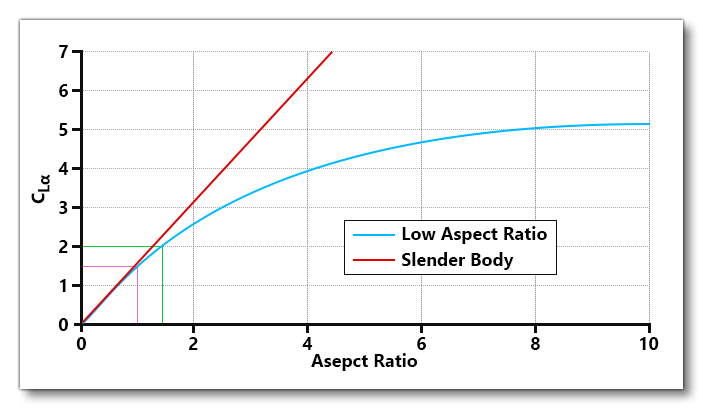
- Elevator aspect ratio is usually between 3 and 5, so a good starting value for the elevator coefficient would be between 3.3 and 4.25.
- Rudder aspect ratio is usually between 1 and 2, so a good starting value for the rudder coefficient would be between 1.5 and 3.
Here you should also take a moment to set the Fuselage Lateral CX (fuselage_lateral_cx) value:

Fuselage CX has a default value of 4.0 and should ideally fall between the range of 0.2 and 0.8. This value helps give more YAW stability (ie: how easily the aircraft will return to center).
Finally, you should set the following effectiveness scalars in the Flight Tuning section:
- Elevator Effectiveness (
elevator_effectiveness) - Aileron Effectiveness (
aileron_effectiveness) - Rudder Effectiveness (
rudder_effectiveness)
These are used to scale the different coefficients and can be tweaked later, but to start with we recommend setting them to 1.
Elasticity Settings
You will want to go ahead and setup the following tables in the Geometry section of the Flight Model tab:
- Elevator Elasticity Table (
elevator_elasticity_table) - Aileron Elasticity Table (
aileron_elasticity_table) - Rudder Elasticity Table (
rudder_elasticity_table) - Elevator Trim Elasticity Table (
elevator_trim_elasticity_table)
These tables can be used to scale up or down the different control surface deflection angles depending on the current dynamic pressure:
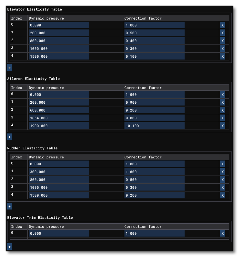
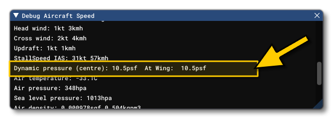
Within the simulation, dynamic pressure (expressed in psf) is airspeed dependent, so these tables allows you to reduce deflection based on the correlation between the given dynamic pressure and a yoke correction factor. You should open the Speed debug window, as there you can see the current dynamic pressure:
The general process for setting these values is as follows:
- Set the elevator/aileron/rudder size and max angle to get the desired stall
- Set the elasticity to 1 at stall speed.
- Set the elasticity to get the maximum G's at max speed.
- Set the elasticity to get the maximum G's at maneuver speed.
Trim
You need to adjust the default trim for the aircraft by setting the Horizontal Tail Incidence (htail_incidence):

For this, you should be flying the aircraft at cruise speed, and then set the horizontal tail incidence until the aircraft is naturally trimmed for cruise speed at trim 0.
Once you have edited this you need to edit the Elevator Trim Neutral (elevator_trim_neutral) value:

This value is used to set set the default take off trim (as well as the green band on the external HUD trim indicator). When setting this value, the aircraft should not be able to take off by itself at, or before, rotation speed - 30% above published rotation speed would be a good starting point.