FUEL SYSTEM
When adding the fuel system to your aircraft you have two options: the simplified/legacy system or the more modern "modular" fuel system. In this tutorial we'll be covering the modular fuel system, as that's the one that you should be using in all but the simplest of aircraft and is the one that will be getting most support in the future.
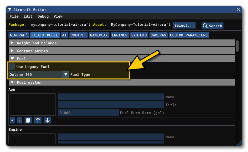
Before continuing you should ensure that the Use Legacy Fuel option is unchecked and that you have selected the Fuel Type (fuel_type) required for the aircraft:
Overview
The modern fuel system takes a modular approach to creating a realistic and accurate fuel system for an aircraft, which permits a great deal of flexibility when designing the aircraft, which the simplified/legacy system cannot provide. The base components for this system are as follows:
- APU (
APU.N): This defines an APU for the fuel system. You can have multiple APU's per system, numbered from 1 upwards. - Engine (
Engine.N): Defines one or more engines (up to a maximum of 4) that form a part of the fuel system. - Tank (
Tank.N): Defines one or more fuel tanks that form a part of the fuel system. - Line (
Line.N): Defines one or more lines that form a part of the fuel system. - Junction (
Junction.N): Defines one or more junctions that form a part of the fuel system. - Valve (
Valve.N): Defines one or more valves that form a part of the fuel system. - Pump (
Pump.N): This sub-section defines one or more pumps that form a part of the fuel system. - Curve (
Curve.N): The curve parameter is essentially a table of one or more paired values, and you can create multiple curves with an incremental index value, eg: Curve.1, Curve.2, Curve.3, etc...
While we strongly advise you to look over the documentation provided for each of these components, this will not help much when it comes to actually setting up your own. For that we recommend the following:
- Make a schematic drawing of the fuel system you wish to model, as having the expected result laid out in a a visual format can help tremendously, since the simulation does not currently provide a visual interface. By creating a schematic you will know exactly what components will be required and have a better idea of how everything should be connected together.
- When adding the components, start by defining the engines, then the tanks, pumps, junctions and valves. These will obviously be missing certain parameters since the connecting lines won't have been added yet, but getting each of the components done first makes adding the lines that much easier. For example, when setting up a pump the destination line is a required parameter. You would leave this part blank for now then come back to it as you start to create the lines.
- Once you have the components set up, you can go ahead and add in the lines, filling in each of the parameters in the other components as you go about it, all the time following the previously created schematic.
- Once everything is defined it is possible to add Triggers (
Trigger.N) which can be used to change the state of some components based on a specific condition.
NOTE: When using the modular fuel system, one may notice that the engine loses thrust and oscillates between full power and almost no power without the throttle being moved, especially with an engine that uses a lot of fuel. This may be due to the fuel system not being able to support the high rate of fuel flow requested. To fix this issue, you can increase the fuel pressure, or increase the volume of the lines or even increases the Fuel Flow (FuelFlowAt1PSI) parameter of the lines.
Setting Up
You can now begin to set up the fuel system by describing its elements. We recommend that you build it alongside - or after - setting up the Electrical System, as fuel pumps and valves may need their own specific circuits if they are electrically driven.
IMPORTANT! When using the modular fuel system, please ensure that the Name property for each element is unique, as it is used to identify their connections.
Engines
First, you'll want to set up the engines that will burn the fuel. This will also include the APUs which will be used to specify the burn rate. Setting them up will look something like this:
APU.1 = Name:APU #FuelBurnRate:33
Engine.1 = Name:LeftEngine #Index:1
Engine.2 = Name:RightEngine #Index:2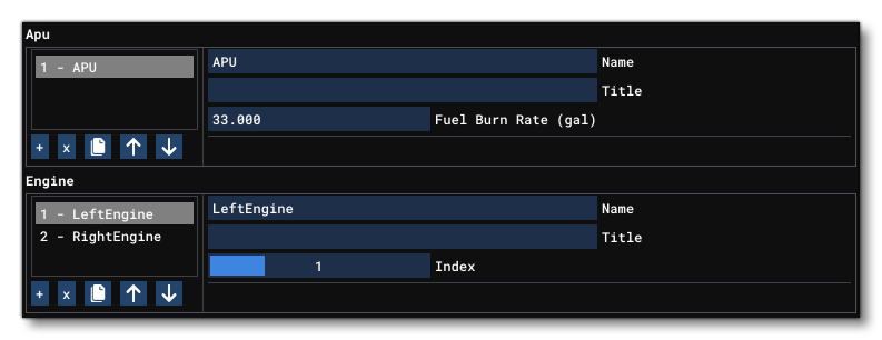
Tanks
Next, you'll want to up the fuel tanks. There are a number of parameters here that can be set to control their behavior - both in how the fuel behaves and how the fuel tanks get filled/emptied when using the Fuel UI in the simulation. Here is an example of setting up some tanks:
Tank.1 = Name:Center #Title:TT:MENU.FUEL.CENTER #Capacity:3000 #UnusableCapacity:0 #Position:-6, 0,1 #Priority:1 #OutputOnlyLines:TankCenterToCenterTankPump1, TankCenterToCenterTankPump2
Tank.2 = Name:LeftInner #Title:TT:MENU.FUEL.LEFT_INNER #Capacity:1800 #UnusableCapacity:0 #Position:-8,-13, 2 #Priority:2 #InputOnlyLines:Eng1ToTank2, Xfer1ToTank2, Xfer1ToTank2_2 #OutputOnlyLines:TankLeftToLeftTankPump1, TankLeftToLeftTankPump2
Tank.3 = Name:RightInner #Title:TT:MENU.FUEL.RIGHT_INNER #Capacity:1800 #UnusableCapacity:0 #Position:-8,13, 2 #Priority:2 #InputOnlyLines:Eng2ToTank3, Xfer2ToTank3, Xfer2ToTank3_2 #OutputOnlyLines:TankRightToRightTankPump1, TankRightToRightTankPump2
Tank.4 = Name:LeftOuter #Title:TT:MENU.FUEL.LEFT_OUTER #Capacity:200 #UnusableCapacity:0 #Position:-13, -27,3 #Priority:3 #OutputOnlyLines:Tank4ToXfer1, Tank4ToXfer1_2
Tank.5 = Name:RightOuter #Title:TT:MENU.FUEL.RIGHT_OUTER #Capacity:200 #UnusableCapacity:0 #Position:-13, 27,3 #Priority:3 #OutputOnlyLines:Tank5ToXfer2, Tank5ToXfer2_2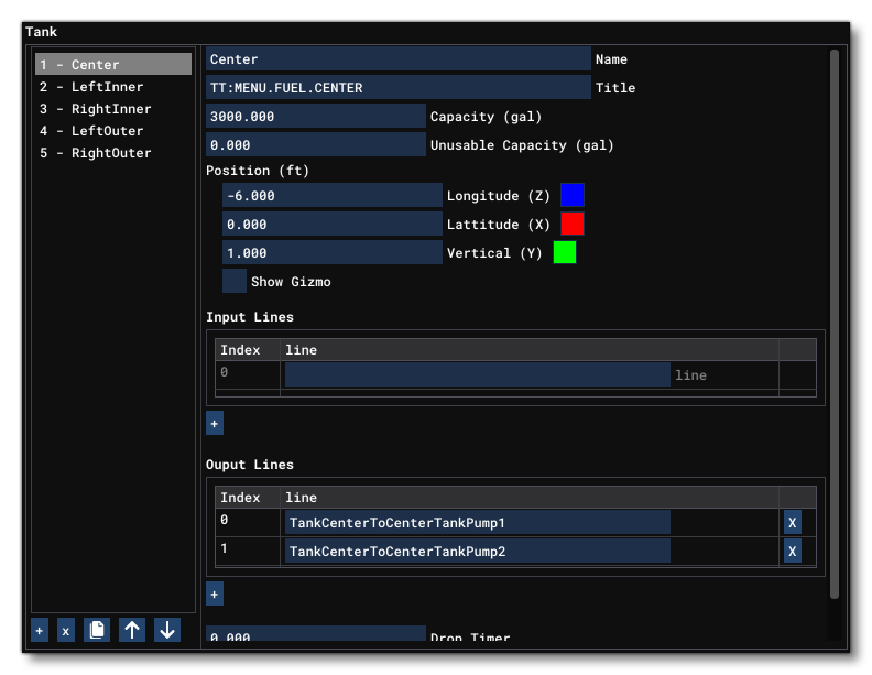
Valves
The next thing you'll want to do is set up the fuel valves that will control when the fuel can go in the various connecting lines. You can set the circuit value to ensure that it does not open if that circuit is not powered (note that it must match a CIRCUIT_FUEL_VALVE defined in the Electrical section. Valves are set up as shown in the following example:
Valve.1 = Name:LeftEngineValve #OpeningTime:3 #Circuit:1
Valve.2 = Name:RightEngineValve #OpeningTime:3 #Circuit:2
Valve.3 = Name:CrossFeedValve #OpeningTime:3 #Circuit:3
Valve.4 = Name:LeftTransferValve2 #Circuit:4
Valve.5 = Name:RightTransferValve2 #Circuit:5
// etc...
Pumps
After the valves, pumps can be set to create pressure and help drive the flow through the system. Once again, if the pump is electrical, it can be connected to a CIRCUIT_FUEL_PUMP. Here is an example:
Pump.1 = Name:CenterTankPump1 #Pressure:29 #DestinationLine:PumpCenterToJuncLeftCenter #TankFuelRequired:Center #Type:Electric #Index:1
Pump.2 = Name:LeftInnerTankPump1 #Pressure:25 #DestinationLine:PumpLeft1ToJuncLeft #TankFuelRequired:LeftInner #Type:Electric #Index:3
Pump.3 = Name:RightInnerTankPump1 #Pressure:25 #DestinationLine:PumpRight1ToJuncRight #TankFuelRequired:RightInner #Type:Electric #Index:4
Pump.4 = Name:APUPump #Pressure:5 #DestinationLine:Pump6ToAPUValve #TankFuelRequired:LeftInner #Type:APUDriven
// etc...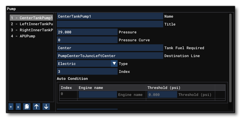
Junctions
The different fuel lines that you will set up later can only be connected one to one, and so you'll want to define a few junctions where the fuel system splits in different lines to allow you to better represent the system. In addition, you can set up options to those lines to be able to open/close some lines from that junction and serve as a fuel selector. The following shows an example of junction setup:
Junction.1 = Name:LeftJunction #InputOnlyLines:PumpLeft1ToJuncLeft, PumpLeft2ToJuncLeft #OutputOnlyLines:Junc1ToEngValveLeft, Junc1ToJuncAPU
Junction.2 = Name:RightJunction #InputOnlyLines:PumpRight1ToJuncRight #OutputOnlyLines:Junc2ToEngValveRight
Junction.3 = Name:CenterLeftJunction #InputOnlyLines:PumpCenterToJuncLeftCenter
Junction.4 = Name:CenterRightJunction #InputOnlyLines:PumpCenter2ToJuncRightCenter
Junction.5 = Name:APUJunction #OutputOnlyLines:JuncAPUToAPUPump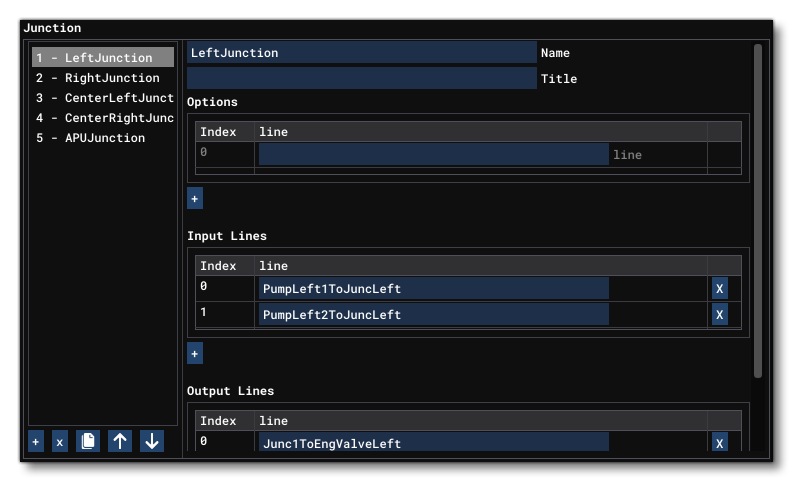
Lines
At this point you can now go ahead and set up the different fuel lines. Since components cannot be connected directly to other components, you will have to create a line between each of them to connect them together. Setting up lines can get a little messy on complex systems, so it is advised to format the CFG file to use spacing and comments to keep the structure as clean and easy to read as possible. The order in which the lines are defined does not matter, until you start setting up the XML/Glasscockpits to look up specific lines, so you should feel free to re-organise things to ensure that this section remains clear, as that will help later if you have an issue to debug. Below we show a shor example of some line definitions, but note that normally you will have far more lines than any other components:
Line.1 = Name:TankCenterToCenterTankPump1 #Source:Center #Destination:CenterTankPump1
Line.2 = Name:TankLeftToLeftTankPump1 #Source:LeftInner #Destination:LeftInnerTankPump1
Line.3 = Name:TankRightToRightTankPump1 #Source:RightInner #Destination:RightInnerTankPump1
Line.4 = Name:TankCenterToCenterTankPump2 #Source:Center #Destination:CenterTankPump2
Line.5 = Name:TankLeftToLeftTankPump2 #Source:LeftInner #Destination:LeftInnerTankPump2
Line.6 = Name:TankRightToRightTankPump2 #Source:RightInner #Destination:RightInnerTankPump2
// etc...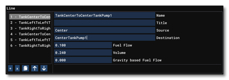
Triggers
Finally, you can set up some triggers to automatize some actions. For example, it is often a good idea to include a trigger for the Autostart and Autoshutdown conditions, to ensure that the fuel system behaves properly when the player presses the ENGINE_AUTO_START or ENGINE_AUTO_SHUTDOWN keys. Here are some examples of trigger definitions:
Trigger.1 = Target:LeftInner #Threshold:250 #Condition:TankQuantityBelow #EffectTrue:OpenValve.LeftTransferValve1, OpenValve.LeftTransferValve2 #EffectFalse:CloseValve.LeftTransferValve1, CloseValve.LeftTransferValve2
Trigger.2 = Target:RightInner #Threshold:250 #Condition:TankQuantityBelow #EffectTrue:OpenValve.RightTransferValve1, OpenValve.RightTransferValve2 #EffectFalse:CloseValve.RightTransferValve1, CloseValve.RightTransferValve2
Trigger.3 = Condition:Autostart_Enabled #EffectTrue:OpenValve.LeftEngineValve, OpenValve.RightEngineValve, OpenValve.CrossFeedValve, OpenValve.APUValve, StartPump.CenterTankPump1, StartPump.LeftInnerTankPump1, StartPump.RightInnerTankPump1, StartPump.CenterTankPump2, StartPump.LeftInnerTankPump2, StartPump.RightInnerTankPump2, StartPump.APUPump
Trigger.4 = Condition:Autoshutdown_Enabled #EffectTrue:CloseValve.LeftEngineValve, CloseValve.RightEngineValve, CloseValve.CrossFeedValve, CloseValve.APUValve, StopPump.CenterTankPump1, StopPump.LeftInnerTankPump1, StopPump.RightInnerTankPump1, StopPump.CenterTankPump2, StopPump.LeftInnerTankPump2, StopPump.RightInnerTankPump2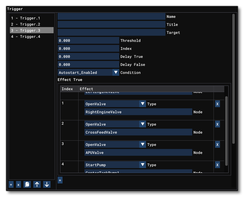
Examples
Given the potential complexity of creating a fuel system using the modular approach, we're providing some examples for you to study to get a better "feel" for how it works and for what is required.
Airbus A320 Fuel SystemAirbus A320 Fuel System
[FUEL_SYSTEM]
Version = Latest
APU.1 = Name:APU #FuelBurnRate:33
Engine.1 = Name:LeftEngine #Index:1
Engine.2 = Name:RightEngine #Index:2
Tank.1 = Name:Center #Title:TT:MENU.FUEL.CENTER #Capacity:3000 #UnusableCapacity:0 #Position:-6, 0,1 #Priority:1 #OutputOnlyLines:TankCenterToCenterTankPump1, TankCenterToCenterTankPump2
Tank.2 = Name:LeftInner #Title:TT:MENU.FUEL.LEFT_INNER #Capacity:1800 #UnusableCapacity:0 #Position:-8,-13, 2 #Priority:2 #InputOnlyLines:Eng1ToTank2, Xfer1ToTank2, Xfer1ToTank2_2 #OutputOnlyLines:TankLeftToLeftTankPump1, TankLeftToLeftTankPump2
Tank.3 = Name:RightInner #Title:TT:MENU.FUEL.RIGHT_INNER #Capacity:1800 #UnusableCapacity:0 #Position:-8,13, 2 #Priority:2 #InputOnlyLines:Eng2ToTank3, Xfer2ToTank3, Xfer2ToTank3_2 #OutputOnlyLines:TankRightToRightTankPump1, TankRightToRightTankPump2
Tank.4 = Name:LeftOuter #Title:TT:MENU.FUEL.LEFT_OUTER #Capacity:200 #UnusableCapacity:0 #Position:-13, -27,3 #Priority:3 #OutputOnlyLines:Tank4ToXfer1, Tank4ToXfer1_2
Tank.5 = Name:RightOuter #Title:TT:MENU.FUEL.RIGHT_OUTER #Capacity:200 #UnusableCapacity:0 #Position:-13, 27,3 #Priority:3 #OutputOnlyLines:Tank5ToXfer2, Tank5ToXfer2_2
Line.1 = Name:TankCenterToCenterTankPump1 #Source:Center #Destination:CenterTankPump1
Line.2 = Name:TankLeftToLeftTankPump1 #Source:LeftInner #Destination:LeftInnerTankPump1
Line.3 = Name:TankRightToRightTankPump1 #Source:RightInner #Destination:RightInnerTankPump1
Line.4 = Name:TankCenterToCenterTankPump2 #Source:Center #Destination:CenterTankPump2
Line.5 = Name:TankLeftToLeftTankPump2 #Source:LeftInner #Destination:LeftInnerTankPump2
Line.6 = Name:TankRightToRightTankPump2 #Source:RightInner #Destination:RightInnerTankPump2
Line.7 = Name:PumpCenterToJuncLeftCenter #Source:CenterTankPump1 #Destination:CenterLeftJunction
Line.8 = Name:PumpLeft1ToJuncLeft #Source:LeftInnerTankPump1 #Destination:LeftJunction
Line.9 = Name:PumpRight1ToJuncRight #Source:RightInnerTankPump1 #Destination:RightJunction
Line.10 = Name:PumpCenter2ToJuncRightCenter #Source:CenterTankPump2 #Destination:CenterRightJunction
Line.11 = Name:PumpLeft2ToJuncLeft #Source:LeftInnerTankPump2 #Destination:LeftJunction
Line.12 = Name:PumpRight2ToJuncRight #Source:RightInnerTankPump2 #Destination:RightJunction
Line.13 = Name:Junc1ToEngValveLeft #Source:LeftJunction #Destination:LeftEngineValve
Line.14 = Name:Junc2ToEngValveRight #Source:RightJunction #Destination:RightEngineValve
Line.15 = Name:JuncAPUToAPUPump #Source:APUJunction #Destination:APUPump
Line.16 = Name:Junc1ToJuncAPU #Source:LeftJunction #Destination:APUJunction
Line.17 = Name:JuncAPUToJunc3 #Source:APUJunction #Destination:CenterLeftJunction
Line.18 = Name:Junc3ToXFeed #Source:CenterLeftJunction #Destination:CrossFeedValve
Line.19 = Name:Junc4ToXFeed #Source:CenterRightJunction #Destination:CrossFeedValve
Line.20 = Name:Junc2ToJunc4 #Source:RightJunction #Destination:CenterRightJunction
Line.21 = Name:Pump6ToAPUValve #Source:APUPump #Destination:APUValve
Line.22 = Name:APUValveToAPU #Source:APUValve #Destination:APU
Line.23 = Name:Eng1ToTank2 #Source:LeftEngine #Destination:LeftInner
Line.24 = Name:Eng2ToTank3 #Source:RightEngine #Destination:RightInner
Line.25 = Name:EngValveLeftToEngLeft #Source:LeftEngineValve #Destination:LeftEngine
Line.26 = Name:EngValveRightToEngRight #Source:RightEngineValve #Destination:RightEngine
Line.27 = Name:Tank4ToXfer1 #Source:LeftOuter #Destination:LeftTransferValve1 #GravityBasedFuelFlow:500
Line.28 = Name:Tank5ToXfer2 #Source:RightOuter #Destination:RightTransferValve1 #GravityBasedFuelFlow:500
Line.29 = Name:Xfer1ToTank2 #Source:LeftTransferValve1 #Destination:LeftInner #GravityBasedFuelFlow:500
Line.30 = Name:Xfer2ToTank3 #Source:RightTransferValve1 #Destination:RightInner #GravityBasedFuelFlow:500
Line.31 = Name:Tank4ToXfer1_2 #Source:LeftOuter #Destination:LeftTransferValve2 #GravityBasedFuelFlow:500
Line.32 = Name:Tank5ToXfer2_2 #Source:RightOuter #Destination:RightTransferValve2 #GravityBasedFuelFlow:500
Line.33 = Name:Xfer1ToTank2_2 #Source:LeftTransferValve2 #Destination:LeftInner #GravityBasedFuelFlow:500
Line.34 = Name:Xfer2ToTank3_2 #Source:RightTransferValve2 #Destination:RightInner #GravityBasedFuelFlow:500
Junction.1 = Name:LeftJunction #InputOnlyLines:PumpLeft1ToJuncLeft, PumpLeft2ToJuncLeft #OutputOnlyLines:Junc1ToEngValveLeft, Junc1ToJuncAPU
Junction.2 = Name:RightJunction #InputOnlyLines:PumpRight1ToJuncRight #OutputOnlyLines:Junc2ToEngValveRight
Junction.3 = Name:CenterLeftJunction #InputOnlyLines:PumpCenterToJuncLeftCenter
Junction.4 = Name:CenterRightJunction #InputOnlyLines:PumpCenter2ToJuncRightCenter
Junction.5 = Name:APUJunction #OutputOnlyLines:JuncAPUToAPUPump
Valve.1 = Name:LeftEngineValve #OpeningTime:3 #Circuit:1
Valve.2 = Name:RightEngineValve #OpeningTime:3 #Circuit:2
Valve.3 = Name:CrossFeedValve #OpeningTime:3 #Circuit:3
Valve.4 = Name:LeftTransferValve2 #Circuit:4
Valve.5 = Name:RightTransferValve2 #Circuit:5
Valve.6 = Name:LeftTransferValve1 #Circuit:6
Valve.7 = Name:RightTransferValve1 #Circuit:7
Valve.8 = Name:APUValve #OpeningTime:3 #Circuit:8
Pump.1 = Name:CenterTankPump1 #Pressure:29 #DestinationLine:PumpCenterToJuncLeftCenter #TankFuelRequired:Center #Type:Electric #Index:1
Pump.2 = Name:LeftInnerTankPump1 #Pressure:25 #DestinationLine:PumpLeft1ToJuncLeft #TankFuelRequired:LeftInner #Type:Electric #Index:3
Pump.3 = Name:RightInnerTankPump1 #Pressure:25 #DestinationLine:PumpRight1ToJuncRight #TankFuelRequired:RightInner #Type:Electric #Index:4
Pump.4 = Name:CenterTankPump2 #Pressure:29 #DestinationLine:PumpCenter2ToJuncRightCenter #TankFuelRequired:Center #Type:Electric #Index:2
Pump.5 = Name:LeftInnerTankPump2 #Pressure:25 #DestinationLine:PumpLeft2ToJuncLeft #TankFuelRequired:LeftInner #Type:Electric #Index:5
Pump.6 = Name:RightInnerTankPump2 #Pressure:25 #DestinationLine:PumpRight2ToJuncRight #TankFuelRequired:RightInner #Type:Electric #Index:6
Pump.7 = Name:APUPump #Pressure:5 #DestinationLine:Pump6ToAPUValve #TankFuelRequired:LeftInner #Type:APUDriven
Trigger.1 = Target:LeftInner #Threshold:250 #Condition:TankQuantityBelow #EffectTrue:OpenValve.LeftTransferValve1, OpenValve.LeftTransferValve2 #EffectFalse:CloseValve.LeftTransferValve1, CloseValve.LeftTransferValve2
Trigger.2 = Target:RightInner #Threshold:250 #Condition:TankQuantityBelow #EffectTrue:OpenValve.RightTransferValve1, OpenValve.RightTransferValve2 #EffectFalse:CloseValve.RightTransferValve1, CloseValve.RightTransferValve2
Trigger.3 = Condition:Autostart_Enabled #EffectTrue:OpenValve.LeftEngineValve, OpenValve.RightEngineValve, OpenValve.CrossFeedValve, OpenValve.APUValve, StartPump.CenterTankPump1, StartPump.LeftInnerTankPump1, StartPump.RightInnerTankPump1, StartPump.CenterTankPump2, StartPump.LeftInnerTankPump2, StartPump.RightInnerTankPump2, StartPump.APUPump
Trigger.4 = Condition:Autoshutdown_Enabled #EffectTrue:CloseValve.LeftEngineValve, CloseValve.RightEngineValve, CloseValve.CrossFeedValve, CloseValve.APUValve, StopPump.CenterTankPump1, StopPump.LeftInnerTankPump1, StopPump.RightInnerTankPump1, StopPump.CenterTankPump2, StopPump.LeftInnerTankPump2, StopPump.RightInnerTankPump2
Airliner fuel systems are usually massive and complex, which is exactly what the modular fuel system is most useful for creating. It can take a bit of time to define everything correctly but the result will be a highly controllable and flexible fuel system. The example (click the header above to expand it) shows the Airbus A320 fuel system as defined in the CFG file.
P-51P-51
[FUEL_SYSTEM]
Version = Latest
Curve.1 = 0:0, 0.3:0.75 , 0.9:0.85, 1:0.98
Engine.1 = Name:Engine #Index:1
Tank.1 = Name:LeftMain #Title:TT:MENU.FUEL.LEFT_MAIN #Capacity:92 #UnusableCapacity:2 #Position:-1, -3.85, -1.55 #Priority:1 #OutputOnlyLines:LTankToFuelSelector
Tank.2 = Name:RightMain #Title:TT:MENU.FUEL.RIGHT_MAIN #Capacity:92 #UnusableCapacity:2 #Position:-1, 3.85, -1.55 #Priority:1 #OutputOnlyLines:RTankToFuelSelector
Tank.3 = Name:CenterAft #Title:TT:MENU.FUEL.FUSELAGE #Capacity:85 #UnusableCapacity:1.6 #Position:-6.0, 0, 0 #Priority:2 #OutputOnlyLines:CTankToFuelSelector
Line.1 = Name:LTankToFuelSelector #Source:LeftMain #Destination:FuelSelector
Line.2 = Name:RTankToFuelSelector #Source:RightMain #Destination:FuelSelector
Line.3 = Name:CTankToFuelSelector #Source:CenterAft #Destination:FuelSelector
Line.4 = Name:FuelSelectorToCutoffValve #Source:FuelSelector #Destination:CutoffValve
Line.5 = Name:CutoffValveToBoosterPump #Source:CutoffValve #Destination:BoosterPump
Line.6 = Name:BoosterPumpToEngineDrivenPump #Source:BoosterPump #Destination:EngineDrivenPump
Line.7 = Name:EngineDrivenPumpToCutoffValve2 #Source:EngineDrivenPump #Destination:CutoffValve2
Line.8 = Name:CutoffValve2ToEngine #Source:CutoffValve2 #Destination:Engine
Valve.1 = Name:CutoffValve #Circuit:1
Valve.2 = Name:CutoffValve2 #Circuit:2
Junction.1 = Name:FuelSelector #InputOnlyLines:LTankToFuelSelector,RTankToFuelSelector, CTankToFuelSelector #OutputOnlyLines:FuelSelectorToCutoffValve #Option:LTankToFuelSelector, FuelSelectorToCutoffValve #Option:CTankToFuelSelector, FuelSelectorToCutoffValve #Option:RTankToFuelSelector, FuelSelectorToCutoffValve
Pump.1 = Name:BoosterPump #Pressure:11 #DestinationLine:BoosterPumpToEngineDrivenPump #Type:Electric #Index:1
Pump.2 = Name:EngineDrivenPump #Pressure:19 #PressureCurve:1 #DestinationLine:EngineDrivenPumpToCutoffValve2 #Type:EngineDriven #Index:1
Trigger.1 = Name:AutoStart #Condition:Autostart_Enabled #EffectTrue:SetJunction.FuelSelector.1, StartPump.EngineDrivenPump, StartPump.BoosterPump, OpenValve.CutoffValve2, OpenValve.CutoffValve
Trigger.2 = Name:AutoShutdown #Condition:Autoshutdown_Enabled #EffectTrue:StopPump.BoosterPump, CloseValve.CutoffValve2, CloseValve.CutoffValve
The modular fuel system can also be useful to define simple but custom fuel system. Here in the P-51 - because the mixture is automatically regulated - the mixture lever was turned into a valve placed just before the engine in the fuel system. This mixture lever is represented by Valve.2. The junction plays the role of the fuel selector and can be given any kind of line combination as an option which can be used to control which tanks are opened or not. Click the header above to expand it and see the example.
DarkstarDarkstar
[FUEL_SYSTEM]
Version = Latest
APU.1 = Name:APU #FuelBurnRate:25
Engine.1 = Name:TurbEngine1 #Index:1
Engine.2 = Name:TurbEngine2 #Index:2
Engine.3 = Name:ScramjetEngine1 #Index:3
Engine.4 = Name:ScramjetEngine2 #Index:4
Tank.1 = Name:LeftMainJetA #Title:TT:MENU.FUEL.LEFT_OUTER #Capacity:592 #UnusableCapacity:0 #Position:-14, -12, 4 #Priority:5 #InputOnlyLines:TurbEngine2ToLeftMainJetA,LeftMainJetAIn #OutputOnlyLines:LeftMainJetAToLeftMainJetAPump,LeftMainJetAOut
Tank.2 = Name:RightMainJetA #Title:TT:MENU.FUEL.RIGHT_OUTER #Capacity:592 #UnusableCapacity:0 #Position:-14, 12, 4 #Priority:5 #InputOnlyLines:TurbEngine1ToRightMainJetA,RightMainJetAIn #OutputOnlyLines:RightMainJetAToRightMainJetAPump,RightMainJetAOut
Tank.3 = Name:Center1JetA #Title:TT:MENU.AIRCRAFT.TANK_CENTER1 #Capacity:592 #UnusableCapacity:0 #Position:16, 0, 8.0 #Priority:2 #InputOnlyLines:Center1JetAIn #OutputOnlyLines:Center1JetAToCenter1JetAPump, Center1JetAOut
Tank.4 = Name:Center2H2 #Title:TT:MENU.AIRCRAFT.TANK_SCRAMJET1 #Capacity:1776 #UnusableCapacity:0 #Position:8, 0, 7.0 #Priority:4 #InputOnlyLines:H2MainDistributorToCenter2H2 #OutputOnlyLines:Center2H2ToCenter2H2Pump, Center2H2ToC2H2Pump
Tank.5 = Name:Center3H2 #Title:TT:MENU.AIRCRAFT.TANK_SCRAMJET2 #Capacity:1480 #UnusableCapacity:0 #Position:-6, 0, 7.0 #Priority:3 #InputOnlyLines:H2MainDistributorToCenter3H2 #OutputOnlyLines:Center3H2ToCenter3H2Pump, Center3H2ToC3H2Pump
Tank.6 = Name:CenterAftJetA #Title:TT:MENU.AIRCRAFT.TANK_CENTER_AFT #Capacity:888 #UnusableCapacity:0 #Position:-16, 0, 7.0 #Priority:1 #InputOnlyLines:CenterAftJetAIn #OutputOnlyLines:CenterAftJetAToCenterAftJetAPump, CenterAftJetAOut
; -------- Front Fuel lines. Front tank to Front pump to Front junction to both engines fuel feed junctions
Line.1 = Name:Center1JetAToCenter1JetAPump #Source:Center1JetA #Destination:Center1JetAPump
Line.2 = Name:Center1JetAPumpToTurbCenter1FuelJunc #Source:Center1JetAPump #Destination:TurbCenter1FuelJunc
Line.3 = Name:TurbCenter1FuelJuncToTurb2FuelFeed #Source:TurbCenter1FuelJunc #Destination:Turb2FuelFeed
Line.4 = Name:TurbCenter1FuelJuncToTurb1FuelFeed #Source:TurbCenter1FuelJunc #Destination:Turb1FuelFeed
; -------- Aft fuel lines with Aft tank and APU. Aft tank to Aft pump to Aft junction. Aft junction distributes to APU through APU valve and to both engines fuel feed junctions
Line.5 = Name:CenterAftJetAToCenterAftJetAPump #Source:CenterAftJetA #Destination:CenterAftJetAPump #Volume:5
Line.6 = Name:CenterAftJetAPumpToTurbCenterAftFuelJunc #Source:CenterAftJetAPump #Destination:TurbCenterAftFuelJunc #Volume:5
Line.7 = Name:TurbCenterAftFuelJuncToAPUJunction #Source:TurbCenterAftFuelJunc #Destination:APUJunction
Line.8 = Name:APUValveToAPU #Source:APUValve #Destination:APU
Line.9 = Name:TurbCenterAftFuelJuncToTurb1FuelFeed #Source:TurbCenterAftFuelJunc #Destination:Turb1FuelFeed #Volume:30
Line.10 = Name:TurbCenterAftFuelJuncToTurb2FuelFeed #Source:TurbCenterAftFuelJunc #Destination:Turb2FuelFeed #Volume:30
; -------- Left Fuel lines. Left tank to left pump to Left fuel feed
Line.11 = Name:LeftMainJetAToLeftMainJetAPump #Source:LeftMainJetA #Destination:LeftMainJetAPump #Volume:5
Line.12 = Name:LeftMainJetAPumpToTurb2FuelFeed #Source:LeftMainJetAPump #Destination:Turb2FuelFeed #Volume:15
; -------- Right fuel lines. Right tank to right pump to right fuel feed
Line.13 = Name:RightMainJetAToRightMainJetAPump #Source:RightMainJetA #Destination:RightMainJetAPump #Volume:5
Line.14 = Name:RightMainJetAPumpToTurb1FuelFeed #Source:RightMainJetAPump #Destination:Turb1FuelFeed #Volume:15
; -------- Cross feed valve to merge left and right fuel feed when valve is open
Line.15 = Name:Turb1FuelFeedToCrossValveJetA #Source:Turb1FuelFeed #Destination:CrossFeedValveJetA #Volume:5
Line.16 = Name:Turb2FuelFeedToCrossValveJetA #Source:Turb2FuelFeed #Destination:CrossFeedValveJetA #Volume:5
; -------- Right fuel feed to right engine (1)
Line.17 = Name:Turb1FuelFeedToTurbEngine1Valve #Source:Turb1FuelFeed #Destination:TurbEngine1Valve #Volume:5
Line.18 = Name:TurbEngine1ValveToTurbEngine1 #Source:TurbEngine1Valve #Destination:TurbEngine1 #Volume:15
; -------- Return line to right engine
Line.19 = Name:TurbEngine1ToRightMainJetA #Source:TurbEngine1 #Destination:RightMainJetA #Volume:5
; -------- Left fuel feed to left engine (2)
Line.20 = Name:Turb2FuelFeedToTurbEngine2Valve #Source:Turb2FuelFeed #Destination:TurbEngine2Valve #Volume:5
Line.21 = Name:TurbEngine2ValveToTurbEngine2 #Source:TurbEngine2Valve #Destination:TurbEngine2 #Volume:15
; -------- return line to left engine
Line.22 = Name:TurbEngine2ToLeftMainJetA #Source:TurbEngine2 #Destination:LeftMainJetA #Volume:5
; -------- Center 2 and 3 tanks are H2 tanks. Separate high pressure system to feed engine 3 and 4
Line.23 = Name:Center2H2ToCenter2H2Pump #Source:Center2H2 #Destination:Center2H2Pump #Volume:10
Line.24 = Name:Center2H2PumpToScramFuelFeed #Source:Center2H2Pump #Destination:ScramFuelFeed #Volume:10
Line.25 = Name:Center3H2ToCenter3H2Pump #Source:Center3H2 #Destination:Center3H2Pump #Volume:10
Line.26 = Name:Center3H2PumpToScramFuelFeed #Source:Center3H2Pump #Destination:ScramFuelFeed #Volume:10
Line.27 = Name:ScramFuelFeedToScramjetEngine1Valve #Source:ScramFuelFeed #Destination:ScramjetEngine1Valve #Volume:10
Line.28 = Name:ScramjetEngine1ValveToScramjetEngine1 #Source:ScramjetEngine1Valve #Destination:ScramjetEngine1 #Volume:10
Line.29 = Name:ScramFuelFeedToScramjetEngine2Valve #Source:ScramFuelFeed #Destination:ScramjetEngine2Valve #Volume:10
Line.30 = Name:ScramjetEngine2ValveToScramjetEngine2 #Source:ScramjetEngine2Valve #Destination:ScramjetEngine2 #Volume:10
; -------- Fuel transfer lines Front Tank
Line.31 = Name:Center1JetAOut #Source:Center1JetA #Destination:FuelTransFrontOutIn #Volume:5
Line.32 = Name:Center1JetAIn #Source:FuelTransFrontInOut #Destination:Center1JetA #Volume:5
Line.33 = Name:FuelTransFrontPumpInput #Source:FuelTransFrontOutIn #Destination:PFuelTransFront #Volume:5
Line.34 = Name:FuelTransFrontPumpOutput #Source:PFuelTransFront #Destination:FuelTransFrontInOut #Volume:5
Line.35 = Name:FuelTransFrontInOutToMainDistributor #Source:FuelTransFrontInOut #Destination:MainDistributor #Volume:5
Line.36 = Name:MainDistributorToFuelTransFrontOutIn #Source:MainDistributor #Destination:FuelTransFrontOutIn #Volume:5
; -------- Fuel transfer lines Aft Tank
Line.37 = Name:CenterAftJetAOut #Source:CenterAftJetA #Destination:FuelTransAftOutIn #Volume:5
Line.38 = Name:CenterAftJetAIn #Source:FuelTransAftInOut #Destination:CenterAftJetA #Volume:5
Line.39 = Name:FuelTransAftPumpInput #Source:FuelTransAftOutIn #Destination:PFuelTransAft #Volume:5
Line.40 = Name:FuelTransAftPumpOutput #Source:PFuelTransAft #Destination:FuelTransAftInOut #Volume:5
Line.41 = Name:FuelTransAftInOutToMainDistributor #Source:FuelTransAftInOut #Destination:MainDistributor #Volume:5
Line.42 = Name:MainDistributorToFuelTransAftOutIn #Source:MainDistributor #Destination:FuelTransAftOutIn #Volume:5
; -------- Fuel transfer lines Left Tank
Line.43 = Name:LeftMainJetAOut #Source:LeftMainJetA #Destination:FuelTransLeftOutIn #Volume:5
Line.44 = Name:LeftMainJetAIn #Source:FuelTransLeftInOut #Destination:LeftMainJetA #Volume:5
Line.45 = Name:FuelTransLeftPumpInput #Source:FuelTransLeftOutIn #Destination:PFuelTransLeft #Volume:5
Line.46 = Name:FuelTransLeftPumpOutput #Source:PFuelTransLeft #Destination:FuelTransLeftInOut #Volume:5
Line.47 = Name:FuelTransLeftInOutToMainDistributor #Source:FuelTransLeftInOut #Destination:MainDistributor #Volume:5
Line.48 = Name:MainDistributorToFuelTransLeftOutIn #Source:MainDistributor #Destination:FuelTransLeftOutIn #Volume:5
; -------- Fuel transfer lines Right Tank
Line.49 = Name:RightMainJetAOut #Source:RightMainJetA #Destination:FuelTransRightOutIn #Volume:5
Line.50 = Name:RightMainJetAIn #Source:FuelTransRightInOut #Destination:RightMainJetA #Volume:5
Line.51 = Name:FuelTransRightPumpInput #Source:FuelTransRightOutIn #Destination:PFuelTransRight #Volume:5
Line.52 = Name:FuelTransRightPumpOutput #Source:PFuelTransRight #Destination:FuelTransRightInOut #Volume:5
Line.53 = Name:FuelTransRightInOutToMainDistributor #Source:FuelTransRightInOut #Destination:MainDistributor #Volume:5
Line.54 = Name:MainDistributorToFuelTransRightOutIn #Source:MainDistributor #Destination:FuelTransRightOutIn #Volume:5
; -------- Fuel transfer lines both H2 Center Tanks
Line.55 = Name:Center2H2ToC2H2Pump #Source:Center2H2 #Destination:PFuelTransC2H2 #Volume:5
Line.56 = Name:PFuelTransC2H2Output #Source:PFuelTransC2H2 #Destination:H2MainDistributor #Volume:5
Line.57 = Name:H2MainDistributorToCenter3H2 #Source:H2MainDistributor #Destination:Center3H2 #Volume:5
Line.58 = Name:Center3H2ToC3H2Pump #Source:Center3H2 #Destination:PFuelTransC3H2 #Volume:5
Line.59 = Name:PFuelTransC3H2Output #Source:PFuelTransC3H2 #Destination:H2MainDistributor #Volume:5
Line.60 = Name:H2MainDistributorToCenter2H2 #Source:H2MainDistributor #Destination:Center2H2 #Volume:5
; -------- MainDistributor Lines for Closed state. Also available as dump valve
Line.61 = Name:MainDistributorToDumpVal #Source:MainDistributor #Destination:DumpValveJetA #Volume:5
Line.62 = Name:H2MainDistributorToDumpVal #Source:H2MainDistributor #Destination:DumpValveH2 #Volume:5
; -------- APUJunction Feeding Lines
Line.63 = Name:APUJunctionToAPUValve #Source:APUJunction #Destination:APUValve #Volume:5
Line.64 = Name:TurbCenterAftFuelJuncToAPUJunction #Source:TurbCenterAftFuelJunc #Destination:APUJunction
Line.65 = Name:Turb1FuelFeedToAPUJunction #Source:Turb1FuelFeed #Destination:APUJunction #Volume:5
Line.66 = Name:Turb2FuelFeedToAPUJunction #Source:Turb2FuelFeed #Destination:APUJunction #Volume:5
; -------- Valves
Valve.1 = Name:TurbEngine1Valve #OpeningTime:1.5 #Circuit:1
Valve.2 = Name:TurbEngine2Valve #OpeningTime:1.5 #Circuit:2
Valve.3 = Name:ScramjetEngine1Valve #OpeningTime:1.5 #Circuit:3
Valve.4 = Name:ScramjetEngine2Valve #OpeningTime:1.5 #Circuit:4
Valve.5 = Name:CrossFeedValveJetA #OpeningTime:3 #Circuit:5
Valve.6 = Name:APUValve #OpeningTime:2 #Circuit:6
; -------- Dump Valves
Valve.7 = Name:DumpValveJetA #OpeningTime:1.5
Valve.8 = Name:DumpValveH2 #OpeningTime:1.5
; -------- fuel feed junctions and intermediary junctions
Junction.1 = Name:Turb1FuelFeed #InputOnlyLines:TurbCenter1FuelJuncToTurb1FuelFeed, TurbCenterAftFuelJuncToTurb1FuelFeed,RightMainJetAPumpToTurb1FuelFeed #OutputOnlyLines:Turb1FuelFeedToTurbEngine1Valve
Junction.2 = Name:Turb2FuelFeed #InputOnlyLines:TurbCenter1FuelJuncToTurb2FuelFeed, TurbCenterAftFuelJuncToTurb2FuelFeed,LeftMainJetAPumpToTurb2FuelFeed #OutputOnlyLines:Turb2FuelFeedToTurbEngine2Valve
Junction.3 = Name:ScramFuelFeed #InputOnlyLines:Center2H2PumpToScramFuelFeed, Center3H2PumpToScramFuelFeed #OutputOnlyLines:ScramFuelFeedToScramjetEngine1Valve, ScramFuelFeedToScramjetEngine2Valve
Junction.4 = Name:TurbCenter1FuelJunc #InputOnlyLines:Center1JetAPumpToTurbCenter1FuelJunc #OutputOnlyLines:TurbCenter1FuelJuncToTurb2FuelFeed, TurbCenter1FuelJuncToTurb1FuelFeed
Junction.5 = Name:TurbCenterAftFuelJunc #InputOnlyLines:CenterAftJetAPumpToTurbCenterAftFuelJunc #OutputOnlyLines:TurbCenterAftFuelJuncToAPUJunction, TurbCenterAftFuelJuncToTurb1FuelFeed, TurbCenterAftFuelJuncToTurb2FuelFeed
; -------- Main distributors for fuel transfer
Junction.6 = Name:MainDistributor #InputOnlyLines:FuelTransFrontInOutToMainDistributor, FuelTransAftInOutToMainDistributor, FuelTransLeftInOutToMainDistributor, FuelTransRightInOutToMainDistributor #OutputOnlyLines:MainDistributorToDumpVal, MainDistributorToFuelTransFrontOutIn, MainDistributorToFuelTransAftOutIn, MainDistributorToFuelTransLeftOutIn, MainDistributorToFuelTransRightOutIn #Option:FuelTransFrontInOutToMainDistributor, MainDistributorToFuelTransLeftOutIn, MainDistributorToFuelTransRightOutIn #Option:FuelTransAftInOutToMainDistributor, MainDistributorToFuelTransLeftOutIn, MainDistributorToFuelTransRightOutIn #Option:FuelTransLeftInOutToMainDistributor, FuelTransRightInOutToMainDistributor, MainDistributorToFuelTransFrontOutIn #Option:FuelTransLeftInOutToMainDistributor, FuelTransRightInOutToMainDistributor, MainDistributorToFuelTransAftOutIn #Option:FuelTransFrontInOutToMainDistributor, MainDistributorToFuelTransAftOutIn #Option:FuelTransAftInOutToMainDistributor, MainDistributorToFuelTransFrontOutIn #Option:MainDistributorToDumpVal
Junction.7 = Name:H2MainDistributor #InputOnlyLines:PFuelTransC2H2Output, PFuelTransC3H2Output #OutputOnlyLines:H2MainDistributorToDumpVal,H2MainDistributorToCenter3H2, H2MainDistributorToCenter2H2 #Option:PFuelTransC2H2Output, H2MainDistributorToCenter3H2 #Option:PFuelTransC3H2Output, H2MainDistributorToCenter2H2 #Option:H2MainDistributorToDumpVal
; -------- Junctions for fuel transfer between JetA tanks. Allows for only one 1-way pump for each tank.
Junction.8 = Name:FuelTransFrontOutIn #InputOnlyLines:Center1JetAOut, MainDistributorToFuelTransFrontOutIn #OutputOnlyLines:FuelTransFrontPumpInput
Junction.9 = Name:FuelTransFrontInOut #InputOnlyLines:FuelTransFrontPumpOutput #OutputOnlyLines:Center1JetAIn, FuelTransFrontInOutToMainDistributor #Option:FuelTransFrontPumpOutput, Center1JetAIn #Option:FuelTransFrontPumpOutput, FuelTransFrontInOutToMainDistributor
Junction.10 = Name:FuelTransLeftOutIn #InputOnlyLines:LeftMainJetAOut, MainDistributorToFuelTransLeftOutIn #OutputOnlyLines:FuelTransLeftPumpInput
Junction.11 = Name:FuelTransLeftInOut #InputOnlyLines:FuelTransLeftPumpOutput #OutputOnlyLines:LeftMainJetAIn, FuelTransLeftInOutToMainDistributor #Option:FuelTransLeftPumpOutput, LeftMainJetAIn #Option:FuelTransLeftPumpOutput, FuelTransLeftInOutToMainDistributor
Junction.12 = Name:FuelTransRightOutIn #InputOnlyLines:RightMainJetAOut, MainDistributorToFuelTransRightOutIn #OutputOnlyLines:FuelTransRightPumpInput
Junction.13 = Name:FuelTransRightInOut #InputOnlyLines:FuelTransRightPumpOutput #OutputOnlyLines:RightMainJetAIn, FuelTransRightInOutToMainDistributor #Option:FuelTransRightPumpOutput, RightMainJetAIn #Option:FuelTransRightPumpOutput, FuelTransRightInOutToMainDistributor
Junction.14 = Name:FuelTransAftOutIn #InputOnlyLines:CenterAftJetAOut, MainDistributorToFuelTransAftOutIn #OutputOnlyLines:FuelTransAftPumpInput
Junction.15 = Name:FuelTransAftInOut #InputOnlyLines:FuelTransAftPumpOutput #OutputOnlyLines:CenterAftJetAIn, FuelTransAftInOutToMainDistributor #Option:FuelTransAftPumpOutput, CenterAftJetAIn #Option:FuelTransAftPumpOutput, FuelTransAftInOutToMainDistributor
; -------- Junction to provide fuel to APU from multiple tanks
Junction.16 = Name:APUJunction #InputOnlyLines:TurbCenterAftFuelJuncToAPUJunction, Turb1FuelFeedToAPUJunction, Turb2FuelFeedToAPUJunction #OutputOnlyLines:APUJunctionToAPUValve
; -------- Fuel feed system pumps
Pump.1 = Name:LeftMainJetAPump #Pressure:100 #DestinationLine:LeftMainJetAPumpToTurb2FuelFeed #Type:Electric #Index:1
Pump.2 = Name:RightMainJetAPump #Pressure:100 #DestinationLine:RightMainJetAPumpToTurb1FuelFeed #Type:Electric #Index:2
Pump.3 = Name:Center1JetAPump #Pressure:100 #DestinationLine:Center1JetAPumpToTurbCenter1FuelJunc #Type:Electric #Index:3
Pump.4 = Name:Center2H2Pump #Pressure:1450 #DestinationLine:Center2H2PumpToScramFuelFeed #Type:Electric #Index:4
Pump.5 = Name:Center3H2Pump #Pressure:1450 #DestinationLine:Center3H2PumpToScramFuelFeed #Type:Electric #Index:5
Pump.6 = Name:CenterAftJetAPump #Pressure:100 #DestinationLine:CenterAftJetAPumpToTurbCenterAftFuelJunc #Type:Electric #Index:6
; -------- JetA tanks fuel transfer pumps
Pump.7 = Name:PFuelTransLeft #Pressure:50 #DestinationLine:FuelTransLeftPumpOutput #Type:Electric #Index:7
Pump.8 = Name:PFuelTransRight #Pressure:50 #DestinationLine:FuelTransRightPumpOutput #Type:Electric #Index:8
Pump.9 = Name:PFuelTransAft #Pressure:50 #DestinationLine:FuelTransAftPumpOutput #Type:Electric #Index:9
Pump.10 = Name:PFuelTransFront #Pressure:50 #DestinationLine:FuelTransFrontPumpOutput #Type:Electric #Index:10
; -------- H2 tanks fuel transfer pumps
Pump.11 = Name:PFuelTransC2H2 #Pressure:100 #DestinationLine:PFuelTransC2H2Output #Type:Electric #Index:11
Pump.12 = Name:PFuelTransC3H2 #Pressure:100 #DestinationLine:PFuelTransC3H2Output #Type:Electric #Index:12
; -------- standard auto start and shutdown. Auto start does not start H2 fuel system
Trigger.1 = Name:AutoStart #Condition:Autostart_Enabled #EffectTrue:OpenValve.TurbEngine1Valve, OpenValve.TurbEngine2Valve, StartPump.LeftMainJetAPump, StartPump.RightMainJetAPump, StartPump.Center1JetAPump, StartPump.CenterAftJetAPump
Trigger.2 = Name:AutoShutdown #Condition:Autoshutdown_Enabled #EffectTrue:CloseValve.TurbEngine1Valve, CloseValve.TurbEngine2Valve, CloseValve.ScramjetEngine1Valve, CloseValve.ScramjetEngine2Valve, StopPump.LeftMainJetAPump, StopPump.RightMainJetAPump, StopPump.Center1JetAPump, StopPump.CenterAftJetAPump, StopPump.Center2H2Pump, StopPump.Center3H2Pump
; -------- Trigger to control CG location through fuel transfer system.
Trigger.3 = Name:FuelTransFrontToSides #Condition:CGBetweenLimits #Threshold:0.17,0.19 #EffectTrue:SetJunction.MainDistributor.1, SetJunction.FuelTransFrontInOut.2, SetJunction.FuelTransLeftInOut.1, SetJunction.FuelTransRightInOut.1, StartPump.PFuelTransFront, StartPump.PFuelTransLeft, StartPump.PFuelTransRight #EffectFalse:SetJunction.MainDistributor.7, SetJunction.FuelTransFrontInOut.1, SetJunction.FuelTransLeftInOut.1, SetJunction.FuelTransRightInOut.1, StopPump.PFuelTransFront, StopPump.PFuelTransLeft, StopPump.PFuelTransRight
Trigger.4 = Name:FuelTransAftToSides #Condition:CGBetweenLimits #Threshold:0.19,0.21 #EffectTrue:SetJunction.MainDistributor.2, SetJunction.FuelTransAftInOut.2, SetJunction.FuelTransLeftInOut.1, SetJunction.FuelTransRightInOut.1, StartPump.PFuelTransAft, StartPump.PFuelTransLeft, StartPump.PFuelTransRight #EffectFalse:SetJunction.MainDistributor.7, SetJunction.FuelTransAftInOut.1, SetJunction.FuelTransLeftInOut.1, SetJunction.FuelTransRightInOut.1, StopPump.PFuelTransAft, StopPump.PFuelTransLeft, StopPump.PFuelTransRight
Trigger.5 = Name:FuelTransSidesToFront #Condition:CGBetweenLimits #Threshold:0.21, 0.25 #EffectTrue:SetJunction.MainDistributor.3, SetJunction.FuelTransAftInOut.1, SetJunction.FuelTransLeftInOut.2, SetJunction.FuelTransRightInOut.2, StartPump.PFuelTransFront, StartPump.PFuelTransLeft, StartPump.PFuelTransRight #EffectFalse:SetJunction.MainDistributor.7, SetJunction.FuelTransAftInOut.1, SetJunction.FuelTransLeftInOut.1, SetJunction.FuelTransRightInOut.1, StopPump.PFuelTransFront, StopPump.PFuelTransLeft, StopPump.PFuelTransRight
Trigger.6 = Name:FuelTransSidesToAft #Condition:CGBetweenLimits #Threshold:0.15, 0.17 #EffectTrue:SetJunction.MainDistributor.4, SetJunction.FuelTransAftInOut.1, SetJunction.FuelTransLeftInOut.2, SetJunction.FuelTransRightInOut.2, StartPump.PFuelTransAft, StartPump.PFuelTransLeft, StartPump.PFuelTransRight #EffectFalse:SetJunction.MainDistributor.7, SetJunction.FuelTransAftInOut.1, SetJunction.FuelTransLeftInOut.1, SetJunction.FuelTransRightInOut.1, StopPump.PFuelTransAft, StopPump.PFuelTransLeft, StopPump.PFuelTransRight
Trigger.7 = Name:FuelTransFrontToAft #Condition:CGBelowLimit #Threshold:0.14 #EffectTrue:SetJunction.MainDistributor.5, SetJunction.FuelTransFrontInOut.2, SetJunction.FuelTransAftInOut.1, StartPump.PFuelTransAft, StartPump.PFuelTransFront #EffectFalse:SetJunction.MainDistributor.7, SetJunction.FuelTransFrontInOut.1, SetJunction.FuelTransAftInOut.1, StopPump.PFuelTransAft, StopPump.PFuelTransFront
Trigger.8 = Name:FuelTransAftToFront #Condition:CGAboveLimit #Threshold:0.25 #EffectTrue:SetJunction.MainDistributor.6, SetJunction.FuelTransFrontInOut.1, SetJunction.FuelTransAftInOut.2, StartPump.PFuelTransAft, StartPump.PFuelTransFront #EffectFalse:SetJunction.MainDistributor.7, SetJunction.FuelTransFrontInOut.1, SetJunction.FuelTransAftInOut.1, StopPump.PFuelTransAft, StopPump.PFuelTransFront
The modular fuel system can be used to define very complex fuel systems with active functionality. Here in the Darkstar (click the header above to expand it and see the example.), the modular fuel system is used to feed 2 * 2 engines, where each pair actually has it's own fuel "loop", and connected to each of these main loops there are secondary loops which are used to transfer fuel between the tanks. This transfer is done automatically through the use of triggers. This is an extreme example, but goes to show just how flexible and detailed the modular fuel system can be.