GEOMETRY
The flight model for Microsoft Flight Simulator relies on the shape of the aircraft to predict its aerodynamic behavior and we have almost entirely dropped the use of multiple tables of data used in legacy simulations. This means that the correct definition of the aircraft's dimension data is of particularly importance to getting it to fly in a realistic and consistent manner, and so on this page we'll be going through the process of setting up the aircraft geometry.
For this section, we strongly recommend that you have the aircraft loaded into the simulation, start a flight, and open the aircraft editor. You should then click on the Geometry section of the Flight Model tab. This will automatically enable the Sim Forces and Sim Dimensions overlays (these can also be enabled/disabled from the Aircraft Editor Debug Menu):

Enabling this will activate the display of the aircraft surface sensors, which will be represented by green boxes, as well as a schematic representation of the fuselage and wings. You can then use these overlays to help resolve correctly the different aircraft geometries that we'll be discussing on the rest of this page. It is also worth noting that each of the parameters mentioned in the following sections is linked to a corresponding description on the pages referring to the flight_model.cfg file, and you should take a moment to read these descriptions as they give additional information which may be helpful when setting their values.
The Wings
We'll start by setting the wing Area and Span in the Geometry section of the Aircraft Editor, which correspond to the parameters wing_area and wing_span in the flight_model.cfg.

Next you can set the Thickness Ratio of the wing in the Geometry panel. This is a ratio of the wing size and most wings are between 2% and 5% thick. In the CFG file, this is the wing_thickness_ratio parameter .

The calculation for this is as follows:
$$\textrm{Local thickness} = \textrm{local_chord(x)} \times \textrm{wing_thickness_ratio}, x = \textrm{lateral_coord}$$
You'll notice that adjusting these values change the position of the green boxes on the wing surface. these boxes are actually the sampling positions that are used by the flight model to determine how the aircraft will fly, and the goal (with the wings) is to have the front row of boxes align with the leading edge of the wing, and the back row of boxes to follow approximately the center of the wing. It's unlikely that these align right now, so we need to continue and define a few more parameters.
At this point you need to send the Sweep in the Geometry tab and the Aero Center Lift (longitudinal position) at the top of the Aerodynamics panel:


These parameters are called wing_sweep and aero_center_lift in the CFG file.
Finally, it's required that you position the wing vertically and adjust its size by adjusting the vertical position (Pos Apex Vert), as well as the Root Chord (measured in ft) and the Dihedral (in degrees).

You can find all these parameters in the Geometry section of the Aircraft Editor, or use the wing_pos_apex_vert, wing_root_chord, and wing_dihedral parameters in the flight_model.cfg.

At this stage, when seen from the top and the sides, you should see that the front line of surface sensors for the wing surfaces are aligned along the leading edge of the wing, and the rear line of surface sensors are aligned along the middle of the wing (this way, the sum of the aerodynamics forces will be aligned at 25% MAC):

It's worth noting that even if you don't have the exact measurements or values required for the above listed parameters, you can still use the visual debugging to get a very close approximation based on the aircraft model. Simply tweak the values then save and resync until you get the surface sensors in the appropriate position.
Fuselage
To adjust the fuselage surface sensor positions and their dimensions to the visual fuselage of the aircraft model, you need to edit the following parameters in the Geometry section of the aircraft editor: Length, Diameter and Center (all in ft):

These parameters are named fuselage_length, fuselage_diameter, and fuselage_center_pos in the CFG file. As with the wings, you can use the simulation overlays to debug and position the fuselage if you don't have the exact values that you require:
 As with the wings, there should also be two rows of green surface sensors - one on either side of the fuselage - that are now placed long the model surface, in close proximity to the "shell" of the fuselage.
The Horizontal Tail
To adjust the horizontal tail's vertical and longitudinal position you can change the Pos Lon and Pos Vert (in ft) inputs in the Aircraft Editor, or edit the htail_pos_lon and htail_pos_vert parameters in the flight_model.cfg. You'll also want to adjust the horizontal tail Thickness Ratio, which is the htail_thickness_ratio parameter in the CFG file.

The calculation for local thickness is as follows:
$$\textrm{Local thickness} = \textrm{local_chord(x)} \times \textrm{htail_thickness_ratio}, x = \textrm{lateral_coord}$$
Next you'll want to adjust the Area, the Sweep, and the Span of the horizontal tail based off of the data you have or using a visual alignment to the model. These parameters are htail_area, htail_span, and htail_sweep in the CFG file. Note that if the aircraft only has an elevator and no horizontal stabilizer, the horizontal tale area should be set to zero.

You'll want to leave the horizontal tail Incidence (htail_incidence in the flight_model.cfg) at zero for the moment, this value will be used to set the default trim of the aircraft later. However you should set the Elevator Area value in the Controls / Properties section of the Geometry panel, which relates to the elevator_area parameter in the CFG file.

If you don't have these exact values available, you can adjust them visually using the debug overlay such that the surface sensor points cover the area correctly. When finished, you should see the surface sensors aligned to the horizontal tail:

The Vertical Tail
We'll now adjust the Vertical Tail the same as we did for the horizontal, starting with the vertical and longitudinal position using the Pos Vert and Pos Lon inputs, and also the Thickness Ratio. These correspond to the vtail_pos_lon, vtail_pos_vert, and vtail_thickness_ratio in the flight_model.cfg.

The calculation for local thickness is as follows:
$$\textrm{Local thickness} = \textrm{local_chord(x)} \times \textrm{vtail_thickness_ratio}, x = \textrm{lateral_coord}$$
Next you'll want to adjust the Area, the Sweep, and the Span of the vertical tail based off of the data you have or using a visual alignment to the model. These parameters are vtail_area, vtail_span, and vtail_sweep in the CFG file.

Finally you should set the Rudder Area value in the Geometry section, which relates to the rudder_area parameter in the CFG file.

After these steps, you should see the surface sensors aligned to the vertical tail, with a second row aligned about halfway along the tail width:

Flaps and spoilers
To define flaps and spoilers, there is both an aerodynamic and a geometric definition. The aerodynamic definition we've already setup in the previous page, so we need to do the geometric definition, which will be fed into the lift and drag polar curves and will be used to perform the virtual wind tunnel normalization of the aircraft's surfaces.
After setting the spoiler and flaps geometry, you should see increased lift forces being applied to the wing over the parts of the wing where the flaps are located:

Flaps
The flaps really only one essential geometric setting which is the ratio of wing span corresponding to how much the flaps will take up on the wing. This is done by changing the Span Outboard (%s) value in the aircraft editor from the Flaps parameter, or by editing the span-outboard value in the flight_model.cfg:

Spoilers
NOTE: If the aircraft does not have spoilers, you can leave all parameters in this section set to 0.
The spoiler geometry is defined in the Geometry panel of the Aircraft Editor, under the Controls / Properties section. In the flight_model.cfg file, you need to set the following parameters:
spoiler_limit, air_spoiler_limit, spoilerons_available, aileron_to_spoileron_gain, min_ailerons_for_spoilerons, min_flaps_for_spoilerons, spoiler_extension_time, spoiler_handle_available, auto_spoiler_available.

Ailerons
Time now to work on the aileron control as it will improve the general stability of the aircraft. Start by defining the Aileron Area (sqft), which aileron_area in the flight_model.cfg file. If you have this exact data, use it. If you don't have this data, then you can approximate it and try to maintain the same order of magnitude when defining the rudder and elevator surface areas later.

Next you'd set the set the Aileron Up and Aileron Down limit angles (in degrees), corresponding to the in the aileron_up_limit and aileron_down_limit in the CFG file. Again, if you have this exact data, use it, but if you don't then you can usually get away with setting the up limit to 20 and the down limit to 15.
NOTE: This type of data is rarely found in a POH but can be found on the website of the FAA.

Now you need to define what percentage of length of the wing is covered by the ailerons. Usually, this distance plus the percentage of the length of the wing covered by flaps, is equal to approximately 100% of the total wing length. This can't currently be set in the editor so you need to edit the aileron_span_outboard parameter in the flight_model.cfg file directly.
Next you can define how much control you want to be applied to the ailerons, depending on the speed of the aircraft. This is a table that defines the ratio of aileron control depending on the amount of dynamic air pressure, and can be set by scrolling to the bottom of the Geometry panel in the Aircraft Editor to the section on Elasticity Tables and selecting the Aileron tab. If you are editing the flight_model.cfg file, you'd use the aileron_elasticity_table parameter.

The current dynamic air pressure is displayed on the Debug Speed window to help adjust the aileron control depending on the current speed:

At lower speeds, up to climb speed, this ratio is usually 100% and it starts decreasing at cruise speed and can reach values close to zero when the plane is flying over speed, above the red bar (complete loss of authority).
Another adjustment that needs to be made is to define the maximum authority of the ailerons. This will be done to achieve the maximum roll speed that is possible with the aircraft at a given speed, and is set from the Aileron Effectiveness setting in the Flight Tuning section, or using the aileron_effectiveness parameter in the flight_model.cfg file.

If you have this value, then you should use it. Otherwise, most aircraft can achieve maximum roll speeds of more than 30 degrees per second. For a GA aircraft 30 to 60 degrees per second is a good start. The above parameter allows you to scale the aileron authority up or down depending on your needs.
When testing, you can find the current roll speed in the Aircraft Editor Tracking debug window, and in the image below you can see an example of the forces that are being applied as a result of the aileron angles when the aileron angles are maximal:

Rudder
The rudder now needs to be setup, so we'll start by defining the Rudder Area (sqft) and the Rudder Limit in the Geometry section, which are the rudder_area and rudder_limit parameters the flight_model.cfg.

As with the other parameters, if have this exact data then use it. If you don't have the data, you can set a value for the rudder area that is in the same order of magnitude as the aileron and elevator surface areas, and for the rudder limit, this is usually between 15° and 30°. The angle needs to be important enough to achieve the maximum possible crosswind landing and de-crab the aircraft.
Similarly to the ailerons, you also need to define the maximum deflection ratio based on the speed of the aircraft by setting up the table that defines the ratio of rudder control depending on the amount of dynamic air pressure. This is done from the Elasticity Tables section of the aircraft editor, or by editing the rudder_elasticity_table parameter in the CFG file.

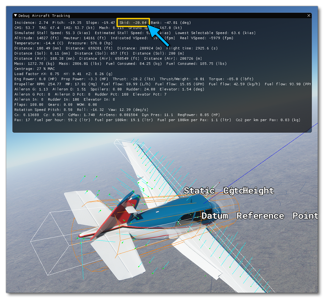
At this stage, you should perform an approach test:
- put the plane at low speed
- go full rudder
- check the skid angle of the airplane
Most planes are able to skid during a stable cross control by about 10° to 20°:
In order to adjust the rudder authority, without changing the rudder surface or maximum deflection angle, which should be based on real data, two parameters are available in the Flight Tuning section of the Aircraft Editor, the Rudder Effectiveness and the Rudder Max Angular Scalar. In the flight_model.cfg file these are under the [FLIGHT_TUNING] header, as rudder_effectiveness, and rudder_maxangle_scalar.
 Also, you may want to go back to adjusting your aileron authority at this stage as most aircraft will have enough aileron control to counter a full rudder deflection and maintain a stable cross controlled flight.
Elevator
The elevator is the last thing that we now need to setup, and we'll start by defining the Elevator Area (sqft) and the Elevator Limit, which are the elevator_area, elevator_up_limit, and elevator_down_limit parameters the flight_model.cfg.

As with the other parameters, if have this exact data then use it. If you don't have the data, you can set a value for the elevator area that is in the same order of magnitude as the aileron and rudder surface areas, and for the elevator limit, this is usually between 20° and 30°. The up limit angle needs to be important enough to allow flaring the aircraft upon landing.
Similarly to the ailerons and the rudder, you also need to define the ratio of elevator control depending on the amount of dynamic air pressure. This is done from the Elasticity Tables section of the aircraft editor, or by editing the elevator_elasticity_table parameter in the CFG file.

Finally, in order to adjust the elevator authority, without changing the elevator surface or maximum deflection angle - which should be based on real data - two parameters are available in the Flight Tuning panel of the Aircraft Editor, the Elevator Effectiveness and the Elevator Max Angular Scalar. These are the parameters elevator_effectiveness and elevator_maxangle_scalar parameters in the flight_model.cfg.

At this stage, you should perform a stall test:
- Put the plane at lower speed
- power off
- try to fly steady without descending
You will need to increase your elevator position closer and closer to the upper limit. When the wing stalls, you will see the lift force vectors on the surfaces change color. Yellow is getting close to stall, red is stalling, blue is a fully stalled surface:

Stalling is computed individually for each surface in the new aerodynamics model of Microsoft Flight Simulator. Most aircraft will allow getting very close to the stall speed limit when the elevator is maintained at the maximum upwards deflection. Some planes will never drop and start descending and others will have a sharp drop. Increasing or decreasing the maximum deflection angle of the elevator, or increasing or decreasing the effect of the elevator deflection, can allow you to achieve a higher or lower maximum angle of attack and therefore change the type of stall of the aircraft.
Stability
Finally, it is time to set the aircraft Stability. Based on the dimensions and geometric definition of the aircraft, the surface based aerodynamics simulation automatically calculates the minimum rotational air friction, but because a real airplane is not made of perfect surfaces with a perfect shape, real rotational friction is always going to be higher. So, to adjust the rotational friction you can go to the Flight Tuning panel and edit the Pitch, Roll, and Yaw Stability settings, or edit the flight_model.cfg file pitch_stability, roll_stability, and yaw_stability parameters.

Note that here you need to enter values that are greater than zero to maintain backwards compatibility with the legacy flight model - however, you can enter 0.01, for example, if you want only the minimum rotational friction. If the plane has more roll inertia, you can enter higher values.