THE FLIGHT MODEL
At this point in the tutorial, you should have your aircraft model and it should be flying in Microsoft Flight Simulator. However, it will not be flying correctly, since the template we've used has a generic flight model of a basic single propeller airplane, which is very unlikely to be appropriate for your aircraft. To rectify this we need to open the flight_model.cfg file, which can be found in the PackageSource folder:
ROOT\<PackageName>\PackageSources\SimObjects\Airplanes\<AircraftName>\flight_model.cfg
We'll be modifying this using a text editor and The Aircraft Editor, but before we do that make sure you have prepared as much information as possible (as listed in the Technical References and Minimum Required Data sections of this tutorial).
It is worth noting that when gathering this data it is important that you understand:
- There are situations where not all data is available, or that the data is inconsistent.
- Some POH may include security margins, so these should be taken into consideration when changing/adding values.
- You can find a lot of aircraft data in the Type Certificate Document on the FAA website, like the controls deflection angles, dimensions, CG limits, etc...
Finally, you can find a more mathematical physical description of the way the Microsoft Flight Simulator flight model works from the following primer:
Plane Performance Spreadsheet
Before continuing, we recommend that you take a moment to fill out the Plane Performance Spreadsheet. This document has a number of blue fields (listed in the table below) which are the ones that you should supply the data for. As you add in each value the rest of the spreadsheet will be updated, and when you're finished you can then use the values from the sheet to help fill in the required parameters for the aircraft in the CFG file.
| Parameter | Input | Units | Description |
|---|---|---|---|
| Stall Speed (CLEAN CAS) | \(V_{s1}\) | kcas |
Stall speed in a "clean" configuration, ie: gear and flaps up (CAS). CFG parameter: |
| Stall Speed (LDG CAS) | \(V_{s0}\) | kcas |
Stall speed in landing configuration (CAS). CFG parameter: |
| Maximum Weight | Weight | lbs |
The maximum weight at which the aircraft is certified for take off due to structural or other limits. CFG parameter: |
| Wing Area | \(S= \int_{0}^{\frac{b}{2}}{c(x)\mathrm{d}x}\) | sqft |
The total wing area. CFG parameter: |
| Wing Span | Span | ft |
The wing span from wing tip to wing tip. CFG parameter: |
| Wing Oswald Efficiency Factor | Wing Oswald \(e\) | Oswald Efficiency Factor |
The correction factor that represents the change in drag with lift of a three-dimensional wing or airplane, as compared with an ideal wing having the same aspect ratio and an elliptical lift distribution. Set to 0.77 to start with (which is good enough for most planes) then adjust as required later, when testing. CFG parameter: |
| Maximum Power | Max Power | hp |
The total maximum engine power with all engines. |
| Thrust Efficiency | Unitless factor | - |
The thrust efficiency factor, usually 1 for turbines and less for piston engines. |
| Max Level Speed (Flap Up) | \(V_{h1}\) | kcas |
The maximum steady level flight speed with the flaps up. |
| Thrust Efficiency Curve | Curve Scalar | - |
Used to adjust the scale of the power polar graph on the spreadsheet. Leave at 1 then adjust as required. |
| Max Level Speed (Flap Down) | \(V_{h0}\) | kcas |
The maximum steady level flight speed with the flaps down. |
| Minimum Drag Lift Coefficient | \(C_{l0}\) | - |
The zero lift coefficient with flaps up. Is used to derive the \(c_{d0}\) and \(C_{lmax0}\) values in the spreadsheet tables. |
| Plane Induced Drag Scalar | Drag Scalar | - |
The induced drag scalar when flying with the flaps up. |
| Minimum Drag Lift Coef (Flap Down) | ff \(C_{l0}\) | - |
The zero lift coefficient with flaps down. Is used to derive the \(c_{d0}\) and \(C_{lmax0}\) values in the spreadsheet tables. |
| Induced Drag Scalar (Flap Down) | ff Ind Drag Scalar | - |
The induced drag scalar when flying with the flaps down. |
| Empty Weight | Weight | lbs |
The weight of the the aircraft when empty, calculated as the sum the manufacturer's empty weight, plus any standard items, plus any operator items. |
| Cruise Speed (Flap Up) | \(V_{c1}\) | kcas |
The aircraft cruising speed with flaps up. |
| Cruise Altitude | Altitude | ft |
The aircraft cruising speed. |
| Specific Fuel Consumption Sea Level | SFCSl | lbs² / hour |
The ratio of the fuel mass flow of the aircraft engine compared to its output power at sea level. |
| Specific Fuel Consumption Cruise Alt | SFCCr | lbs² / hour |
The ratio of the fuel mass flow of the aircraft engine compared to its output power at cruise altitude. |
| Max Fuel Load | Fuel | lbs |
The maximum weight of fuel when fully loaded. |
| Maximum Cruise Level Speed (Flap Up) | \({V_h}{C_1}\) | kcas |
The maximum speed when at cruise altitude. |
| Maximum Cruise Altitude | \(C_{alt}\) | ft | The maximum permitted altitude for cruising. |
| Power Ratio At Cruise Altitude | Ratio | Percent | Generally only required for turbine engines and set the percentage power loss in thrust at cruising altitude. |
| Ceiling Altitude | Altitude | ft | The ceiling altitude is the maximum usable altitude of an aircraft (also called the service ceiling). |
| Ceiling Altitude Max Rate Of Climb | Rate | ft / min | This is the ceiling altitude above which the maximum rate of climb begins to drop. |
| Ceiling Altitude Remaining Power Ratio | Ratio | Percent | Set the percentage power of lost from thrust at the (service) ceiling altitude. |
Filling in these values should give you approximate values for the other parameters in the spreadsheet, which can then be used to fill in some of the most important values in the Flight Model Config, and the Engine Config files. Note that you can play with some values - like Max Level Speed, for example - until the rest of the parameters match those of the aircraft POH. Also note that you can usually find the \(V_y\) and \(V_x\) values and Best Glide and the Glide Ratio (finesse max) values in the POH.
Now that you have this data, you can continue on to edit the actual CFG files related to your aircraft, as explained in the following sections of this tutorial.
The Aircraft Editor
Before continuing on to edit the actual files related to the aircraft performance and handling, you should have it loaded into the simulation as outlined on the page about Package Building. Once the aircraft package has been loaded, you'll need to start a flight, as we'll be using the The Aircraft Editor to edit some of the values for the flight model, and we'll also be using some of the debug windows and tools that the editor offers to better visualise these changes as well as make editing them easier. So, go ahead and do that now before continuing on any further.
It is important to note that NONE of the changes that you make - either to the files directly in a text editor or to the files through the Aircraft Editor - will be applied to the aircraft until you have resynced everything from the editor File menu. Which option you choose will depend on how you have edited the files:
-
Resync
This option will re-synchronise the files used by the aircraft currently being edited. Use this option if you have manually edited the CFG files and want to apply the changes to the simulation.
-
Save And Resync
Selecting this will save any changes made to the settings in the aircraft editor and then re-synchronise those changes.
The Reference Datum Position
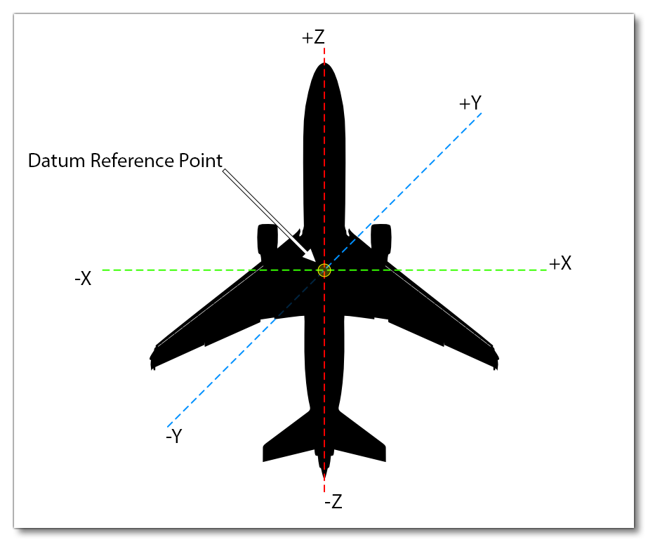
Many positions of components on an aircraft are given relative to the datum reference point for the aircraft. These are generally defined in the following order:
- longitudinal (Z), where to the front is positive and to the back negative
- lateral (X), where to the right is positive and to the left negative
- vertical (Y), where vertically up is positive and to the down is negative
The image below illustrates this:
 The datum reference point itself is specified in the
 [WEIGHT_AND_BALANCE] section of the flight_model.cfg file, and the actual physical details of how we calculate this point is given in the Reference Datum Frame section of the page on Flight Model Physics. By default this will be set to (0, 0, 0) which will correspond with the actual (0, 0, 0) position of the model mesh. However, you may want to change this to something more appropriate since all the geometric parameters we'll be discussing in the following pages will be set relative to this position:

In general you can keep the default (0,0,0) of the model, or use the front of the aircraft nose, or use the manufacturer reference if mentioned in the POH - for example for the Cessna 172, the manufacturer reference is the firewall between the engine and the cabin.