THE MODELLING PROCESS
Once you have your file setup and understand the naming conventions you should be using, it's time to start modelling the aircraft exterior, paying very close attention to get the proportions and sizes correct based on all the Visual References and Technical References that you have acquired. This tutorial assumes you know how to use your chosen modelling software and so won't go into detail on how to actually create the model. However this page will give recommendations on some general best practices that should be followed when creating an aircraft.
Airframe Poly Count
Before getting started, it's good to be aware of the limitations of the simulation and the recommended polygon count for the aircraft that you are making. Aircraft that go over the recommended limits will be considered un-optimized and may cause issues when used in the simulation, so we strongly recommend that you pay attention to these values when creating your models.
The table below is a general guide as to how many triangles you can spend on a single plane asset:
| Plane Size | Plane Description | Triangle Count Exterior |
|---|---|---|
| Extra Large plane | Jumbo Jet | 1,000,000 tris |
| Large plane | Large Passenger Jet | 500,000 tris |
| Medium plane | Small Passenger Jet | 300,000 tris |
| Small plane | Single/Double Seater | 200,000 tris |
Since this part of the documentation deals with creating the airframe model with the highest possible fidelity for LOD0, the above table doesn't show the polgon count for the other LODs. However, you can find all the information on the optimal number of polygons to use for each LOD level on the following page:
Safety Cuts
When creating your airframe meshes they should be as clean and even as possible, and they should make good use of safety cuts. The image below illustrates this, and if you mouse over it you can see how the example mesh looks using a single smoothing group:


Turning Edges
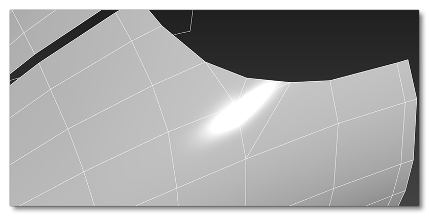
An important part of creating the aircraft model is ensuring that all the invisible polygon edges are turned so that the specular highlights and reflections have minimal distortions and flow correctly along the mesh. The image below shows a model with bad edges, and if you mouse over the image, you can see how it would look when corrected:


On large areas of mesh it is good practice to set the render mode to facetted in order to see the mesh with no smoothing. When in this view, you should be able to see nice clean gradients across your mesh, and this view will greatly will help when it comes to turning edges correctly.
To get a better idea if the difference this makes, here are two final images taken of the fuselage of a 747. The top image is without correcting the invisible edges and the bottom image is with corrected edges (if you mouse over the images you can see the mesh without the wireframe to see how the hidden edges affect lighting and gradients):


Quads And TurboSmooth
Where possible you want to minimise the amount polys that are something other than quads, as this can negatively affect the results when adding a TurboSmooth modifier or when increasing the resolution of the mesh using freeform tools. As a result, it is much difficult to quickly select poly rings and loops in order to use flow connect (es explained further down this page).
The image below shows a mesh that has been created using polygons other than quads to create the rounded edge, and if you mouse over it you can see what happens if you use a TurboSmooth modifier - you get pulled edges and the specular highlights are negatively affected:

Using quads will also offer superior results on lower resolution meshes when a TurboSmooth modifier is applied too, as illustrated in the following example (mouse over it to see the mesh with the modifier applied):

In order to maintain a higher quality mesh and UVs, you should avoid using TurboSmooth modifiers on the exportable mesh. Only use this feature to quickly up-res the mesh to the required resolution, as it will then be collapsed in order to clean it up and remove unnecessary edges and fix any UV distortions.
Increasing Mesh Resolution
In order to get better control over the increase of mesh resolution without relying on TurboSmooth, we recommend that you use the 3DS Max Freeform modelling tools as much as possible. For example, when using the Flow Connect and Set Flow tools to increase resolution of the model we have full control over the poly usage.
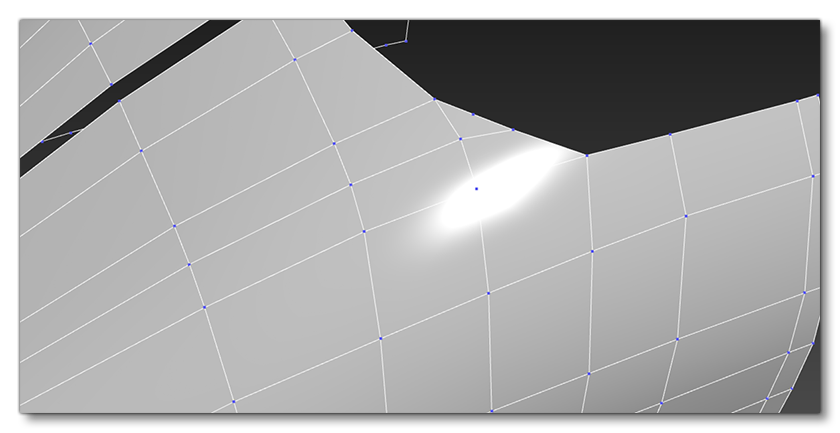
In the following example image we have selected the edge ring:
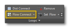
 We then click on Flow Connect to add a new loop that conforms to the average normal direction of the neighbouring edges:
Which gives the following result:
 You would then repeat this process across the rest of the mesh until you have achieved the desired result:
 Finally, by using the Set Flow options to tidy the edge spacing, you can remove edges and reintroduce triangles to optimise the mesh:
 In the image below you can see a final result, where the one on the left is 334 tris with TurboSsmooth and the one on the right is 241 without TurboSmooth but using the Freeform modelling tools to add geometry manually, giving you a smoother finish:

It is worth noting that adding a meshSmooth modifier over the top of the tidied up mesh will give a cleaner final result in the event of an ultra-high resolution LOD, and this is also especially useful when baking normals:
 IMPORTANT! Always ensure that the shape you are recreating is not negatively affected when increasing resolution, and always refer back to the reference when adding or removing geo resolution to ensure you are not straying from the real plane.
Notes On Lights
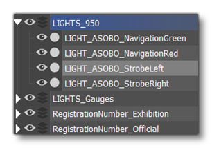
When adding lights to the aircraft model we use emissive meshes. For example, the images below show the nav and strobes lights located on both wings of the aircraft:
 There are two emissive meshes used to make the light object:
 LIGHT_NavigationRed and LIGHT_StrobeLeft. They have to be separated with a centered pivot and then have a Reset Xform applied on it. Once that has been done, we can then place them into a separated layer that you would tick in the multi exporter (and then we can use them in the CFG files for the aircraft).
 It is worth noting that they can also be parented to animated objects, like the landing lights, and that for some lights you will have to take into consideration the orientation of the mesh. For further information on lights, please see the following page:
First Pass Results
Following the general principles outlined on these pages, your aim is to finalize a "first pass" of the aircraft exterior model that is accurate in shape and scale, and that has the essential mechanical component animations in place, ie: ailerons, rudder, flaps, landing gear, etc...

Once you have the first pass done, you would go ahead and configure the aircraft for testing in the game, and once everything has been set up correctly return and give the model and textures a final tweak and polish.