WEIGHT AND BALANCE
Setting up the aircraft weight and load distribution is very important as it's a key factor in the Microsoft Flight Simulator 2024 flight model and will determine a lot of how the aircraft will finally handle (note that you can find a lot of this information - like the center of gravity and loading station positions and weights - in the POH). The first parameters we'll discuss on this page will be set through the SimObject Editor Weight And Balance ([WEIGHT_AND_BALANCE]) section of the Flight Model tab:

By default, clicking this will change the debug visualisation to show basic shapes for weight and distribution. This can be toggled on and off using the Debug menu in the SimObject Editor and selecting Weight. In this visualisation, the following colours will be used:
- The empty CG will be displayed as a two green boxes.
- The pilots will be represented by pink boxes.
- Fuel tanks will be orange boxes.
- The engines will be represented as red boxes.
- The landing gear will be shown with yellow boxes.

Another useful debug window which you can open to help with the weight and balance of the aircraft is the Sim Tuning window. This window contains the actual weights as used by the simulation at the moment you view the window:

Aircraft Weight And Center Of Gravity
To start with, you should fill out the different maximum weights - the minimum information required here would be the Max Gross Weight (max_gross_weight) so exure that you have that at least - and the Empty Weight (empty_weight) in the CFG file:

The empty weight is different for each aircraft depending on the avionics and configuration, so the information in the POH will generally be good enough. For more precise data, you will have to find the weight and balance load sheet for the specific aircraft. Also note that for the max gross weight, bigger aircraft could have a max ramp weight allowing more weight than the takeoff weight, because of the few hundred pounds of fuel burned on the ground for taxi and run up.
Once you have the weights set up, you should also define the position of the CG of the empty aircraft through the Empty Weight CG Position (empty_weight_CG_position) parameter, keeping in mind that this is relative to the The Reference Datum Position:

If you have the actual data for the aircraft, then you can mathematically calculate the CG position using the following formula:
$$\frac{Moment}{Weight} = CG Arm$$
Where the moment is in inches/lbs, the weight is in lbs and the CG arm is in inches. Usually you can find the empty weight value in the POH, as shown in the following example:
 Using this example POH and the formula given above we get this calculation:
$$\frac{62600}{1642} = 38.12$$
So, the CG arm is 38.12 inches from the reference datum.
Unfortunately, data is not always available to position the empty CG on an aircraft, but the correct positioning of the CG is critical for the plane to fly normally. Here are a few tricks to help with setting this up:
- The lateral (x) component of the empty CG position is usually zero.
- The vertical (y) component of the empty CG is usually located close to the middle of the fuselage on the vertical axis. For a high wing, it will be a little higher, for a low wing, a little lower. Note that of all the values, this one is hardest to calculate or find, and as such you may need to perform some trial-and-error to get something correct for the aircraft. A good rule for this is to use the expected thrust line to set the vertical positioning, as this will be based on the expected pitch moment when increasing the power:

Thrust Line Below CG - Nose pitches up
In addition to other aerodynamic effects, there will be an additional pitch-up moment.

Thrust Line Through CG - Nose pitches up to a lesser degree
The airplane will begin a climb, or - at least - descend more slowly. Pitch-up will not be as great.

Thrust Line Above CG - Nose pitches down
This is the opposite of the above examples, all of which are dependent on a variety of other factors.
- To position the longitudinal (z) component of the empty CG, the best method is to use the % MAC. If that information is available, use it directly. If not, usually, the empty CG will be located at around 20% MAC. The % MAC of the empty CG is displayed in the debug window of the weight debug screen. A % MAC outside of the 10% to 35% range may result in an uncontrollable aircraft.
Fuel Tanks
A major factor when dealing with the aircraft weight and center of gravity is the weight and positioning of the fuel tanks. To help with debugging you should ensure that the Weight debug window is open, as fuel tanks will be shown directly in the simulation using orange rectangles, making it easier to see where they are being positioned (relative to the The Reference Datum Position):

For most aircraft with engines, you will want to set up a full Fuel System to correctly simulate the flow of fuel from the tanks to the engines, and this is done through the [FUEL_SYSTEM] section of the Flight Model tab in the SimObject Editor. However, we are only concerned with the tanks, as those are going to affect the weight and balance of the aircraft, so that's all we'll be setting up here for the moment and the rest of the fuel system setup is described on the dedicated Fuel System page.
NOTE: This section will not be visible in the SimObject Editor when the Use Legacy Fuel checkbox is checked.
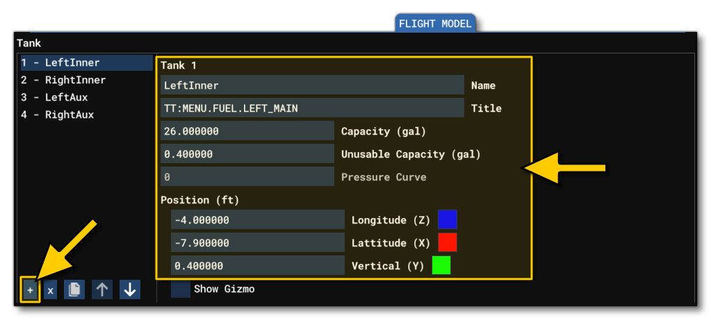
From this section, you add a tank (Tank.N in the CFG file) with the + button at the bottom, then give the tank a name and fill in (at least) the Capacity and Unusable Capacity. Once you've done that you can go ahead and define the Position of the tank, then repeat the process for all the tanks on the aircraft.
Station Loads
Another important part of balancing the aircraft is setting up the various station load points. These are the positions of the pilots and other load stations - such as luggage - within the aircraft, and can be set from the Station Load Factory Mass part of the Weight And Balance section:
NOTE: Pilot, copilot and passenger stations are automatically limited to 220 lbs in the UI to avoid overweight.

As with other weight and balance options, you can position these extra weights using Long, Lat and Vert position (in ft) relative to the center of the model, and also give them a name and a mass (mass here is measured in lbs). Note that you can add entries into this list using the + button at the bottom, if required. Also note that you can supply an optional Station Name that corresponds to each of the load stations. This parameter defines a name that will be used in the payload dialog, and has a 15 character limit. Omission of this will result in a generic station name being used. These parameters are named as follows in the flight_model.cfg, in the [WEIGHT_AND_BALANCE] section:
When positioning these stations, it can be useful to check the Show Gizmo option and manually place them in the simulation, and if you have the Weight debug window open, they will be shown as pink boxes in the view, where the size of the box is relative to the mass assigned.
IMPORTANT! For station loads that are meant to hold changing weights - ie: passengers, luggage, pilot, etc... - the mass should be set to 0. The simulation will adjust the mass assigned to each station automatically based on the values set up in the navigation graph, as explained in Mass Sections, below.

Mass Sections
All aircraft will require, at minimum, one navigation_graph.cfg to set up the pilot seating and positioning, and in this file you'll be defining at least one Mass Section. Mass sections are used to assign variable mass to a station load, and when defining them you give a maximum mass (in lbs) that the station can hold, and then the simulation will assign an amount based on verious different factors. Adding a mass section is done by clicking the + button and then giving the section a unique name, a station load name, and the maximum mass:

The full setup of these mass sections, along with the navigation graph file in general, is described in full on the following pages:
Engine
Another important item to set regarding the weight and balance of the aircraft is the position of the engines. This is done from the engines.cfg tab of the SimObject Editor, in the General Engine Data section:

As with other things mentioned on this page, you can add an engine by clicking the + button underneath, and then you can position it using the z/x/y inputs, or by checking Show Gizmo and then positioning them visually in the simulation. Positioning the engine can be made easier when the Weight debug window open as the engine position will be shown using a red cube, permitting you to exactly visualise where it's going to be:
 The red box should be positioned where the thrust force will apply, generally at the center of the propeller or at the exhaust of a jet engine.
If you want to edit the engine position in the CFG file, you would change the Engine.N values in the [GENERALENGINEDATA] section of the flight_model.cfg.